
Concentric Vent Termination Kit for Condensing Furnaces
SPECIAL VENTING REQUIREMENTS FOR
INSTALLATIONS IN CANADA
Installation in Canada must conform to the requirements of
CSA B149 code. Vent systems must be composed of pipe,
fittings, cements, and primers listed to ULC S636. This
concentric vent termination kit has been certified to ULC
S636 for use with piping and vent components which have
been certified to this standard. Follow the manufacturer’s
instructions in the use of primer and cement and never
use primer or cement beyond its expiration date.
The safe operation, as defined by ULC S636, of the vent
system and this termination kit is based on following these
installation instructions, the vent system manufacturer’s
installation instructions, and proper use of primer and
cement. Acceptability under Canadian standard CSA
B149 is dependent upon full compliance with all installation
instructions. Under this standard, it is recommended that
the vent system be checked once a year by qualified
service personnel. The authority having jurisdiction (gas
inspection authority, municipal building department, fire
department, etc) should be consulted before installation
to determine the need to obtain a permit.
CONSIGNES SPÉCIALES POUR
L’INSTALLATION DE VENTILLATION AU
CANADA
L’installation faite au Canada doit se conformer aux exigences
du code CSA B149. Ce systême de ventillation doit se
composer de tuyaux, raccords, ciments et apprêts conformes
au ULC S636. Ce systême de ventillation concentrique a été
certifié ULC S636 pour être utilisé avec les composantes qui
sont certifiés. Bien suivre les indications du manufacturier
lors de l’utilisation de l’apprêt et du ciment et ne pas utiliser
ceux--ci si la date d’expiration est atteinte.
Le bon fonctionnement de ce systême de ventillation est
conditionnel à l’installation tel que défini par le ULC S636
c’est à dire: bien suivre les consignes ci--haut mentionnées
ainsi que les instructions du manufacturier et aussi une bonne
utilisation de l’apprêt et du ciment. L’acceptation du standard
Canadien CSA B419 est directement relié à l’installation
conforme aux instructions ci--haut mentionnées. Le standard
Canadien recommande l’ inspection par un personel
qualifié et ce, une fois par année. Les autoritées ayant
juridiction (inspecteurs de gas, inspecteurs en bâtiments,
département des incendies, etc) devraient être consultées
avant l’installation afin de déterminer si un permis est requis.
IMPORTANT SAFETY INFORMATION
Please read all instructions before installing this kit. Pay
attention to all safety warnings and any other special
notes highlighted in the manual. Safety markings are
used frequently throughout this manual to designate a
degree or level of seriousness and should not be ignored.
WARNING indicates a potentially hazardous situation that
if not avoided, could result in personal injury or death.
CAUTION indicates a potentially hazardous situation that
if not avoided, may result in minor or moderate injury or
property damage.
WARNING:
RISK OF ELECTRICAL SHOCK
Shut off all electrical power to the unit before
performing any maintenance or service on
the system. Failure to follow this warning can
cause serious injury, fire, electrical shock, or
death.
• The installer performing this work assumes all
responsibility when installing this kit. These instructions
are primarily intended to assist qualified individuals
experienced in the proper installation of this kit. Some
local codes may require licensed installation/service
personnel for this type of equipment. Safety should
always be the deciding factor when installing this product
and using common sense plays an important role as
well. Improper installation of the components or failure
to follow safety warnings could result in serious injury,
death, or property damage.
• Unlessnotedotherwiseintheseinstructions,onlyfactory
authorized parts or accessory kits may be used with this
product. Improper installation, service, adjustment, or
maintenance may cause fire, electrical shock or other
hazardous conditions which may result in personal injury
or property damage.
• Pleasereadallinstructionscarefullybeforestartingthe
installation. If a problem occurs, check the instructions
and follow recommendations given.
• Theinformationshownintheseinstructionsmustbe
followed during the installation of this kit. Unqualified
individuals should not attempt to interpret these
instructions or install this equipment. If you do not
possess mechanical skills or tools, call your local dealer
for assistance.
• Usecautionwhenhandlingtheapplianceorremoving
components. Personal injury can occur from sharp metal
edges present in all sheet metal constructed equipment.
INSTALLATION INSTRUCTIONS

2
support material.
IMPORTANT: Make sure the termination height is above
the roof surface or anticipated snow level (12 inches
in U.S.A. or 18 inches in Canada). If the assembly is
too short to meet the height requirement, the 2 pipes
supplied in the kit may be replaced by using the same
diameter, field supplied SDR-26 PVC (D2241) pipe. Do
not expand dimension "D" more than 60 inches. See
Figure 3.
WARNING:
Do not operate the furnace with rain cap removed.
Recirculation of combustion products may
occur, or water may accumulate inside larger
combustion air pipe and flow into the burner
enclosure. Failure to follow this warning could
result in product damage or improper operation,
personal injury or death.
CAUTION:
DO NOT use field supplied couplings to extend
pipes. Airflow restriction will occur and the
furnace pressure switch may cause intermittent
operation.
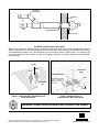
NOTE: Instead of cementing the smaller pipe to the rain
cap, a field-supplied stainless steel screw may be used to
secure the 2 components together when field disassembly
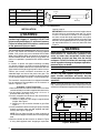
Figure 1. Kit Components
Figure 2. Dimensions
B
1 3/16
1 1/2
D
F
A
E
C In. Dia.
KIT NO. A B C D E F
904176 (3”) 38 7/8 3 4 1/2 21 1/8 7 3/8 6 1/2
904177 (2”) 33 3/8 2 3 1/2 16 5/8 6 1/4 5 3/4
904952 (2”) 33 /38 2 3 1/2 16 5/8 6 1/4 5 3/4
904953 (3”) 38 7/8 3 4 1/2 21 1/8 7 3/8 6 1/2
INSTALLATION
WARNING:
These kits are to be used only for terminating
condensing Category IV furnaces. DO NOT use
kits to terminate Category I, II, or III vent furnaces.
Failure to follow these instructions could result
in fire, personal injury, or death.
The concentric vent is made of PVC. When joining PVC
to PVC, use cement that conforms to ASTM standard
D2564. PVC primer must meet standard ASTM F656.
When joining ABS to ABS, use cement that conforms to
ASTM standard D2235. When joining PVC to ABS, use
cement as specified in procedure from ASTM standard
D3138.
In Canada, all plastic vent pipes and fittings including
any cement, cleaners, or primers must be certified as a
system to ULC S636. However this requirement does not
apply to the finish flanges or piping internal to the furnace.
Consult your furnace installation instructions for the
allowable length and size of the plastic vent pipe. The
concentric vent termination assembly is equal to 4 feet of
3" inlet and outlet pipe, or 3 feet of 2" inlet and outlet pipe.
The concentric vent termination kit is shipped assembled
but not cemented. Disassemble the kit and cement as
shown in Figures 1 and 2.
Procedure 1: Roof Termination
1. Determine the best location for the termination kit. Refer
to the Installation Instructions supplied with the furnace.
2. Cut one hole, 5” diameter when using a 3" kit or a 4"
diameter hole when using a 2" kit.
3. Partially assemble the concentric vent termination kit
as shown in Figures 1 and 2.
a. Cement Y concentric vent fitting to larger diameter
kit pipe. See Figure 1.
b. Cement rain cap to smaller diameter kit pipe. See
Figure 1.
4. Install cemented Y concentric fitting and pipe assembly
through structure's hole and field supplied roof boot/
flashing. See Figure 3 (page 3).
NOTE: Do not allow insulation or other materials to
accumulate inside pipe assembly when installing through
hole.
5. Secure assembly to roof structure as shown in Figure
3 using field supplied metal strapping or equivalent
KIT NO. DESCRIPTION USAGE
Inside Pipe
Y Concentric
Fittin
g
Outside Pipe
Rain Cap
904176 Concentric Vent Kit, 3 inch, US US Only
904177 Concentric Vent Kit, 2 inch, US US Only
904952 Concentric Vent Kit, 2 inch, US/CAN US/CAN
904953 Concentric Vent Kit, 3 inch, US/CAN US/CAN

3
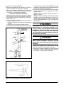
Figure 3. Roof Installation
Maintain 12" (18" for
Canada) Min. clearance
above roof or highest
anticipated snow level,
max. 24" above roof.
Combustion
Air
Support
(Field Supplied)
Vent
Combustion Air
45˚ Elbow
(Field Supplied)
Roof Boot/
Flashing
(Field Supplied)
Vent
through structure's hole (Figure 5). NOTE: Do not allow
insulation or other materials to accumulate inside pipe
assembly when installing through hole.
5. Secure the assembly to the structure as shown in Figure
5 using field supplied metal strapping or equivalent
support material.
NOTE1: Ensure termination location clearance as
shown in Figure 5.
NOTE2: If assembly needs to be extended, the 2 pipes
supplied in the kit may be replaced by using the same
diameter, field supplied SDR-26 PVC (D2241) pipe.
Do not expand dimension "D" more than 60 inches
(See Figure 2).
WARNING:
Do not operate the furnace with rain cap removed.
Recirculation of combustion products may
occur, or water may accumulate inside larger
combustion air pipe and flow into the burner
enclosure. Failure to follow this warning could
result in product damage or improper operation,
personal injury or death.
CAUTION:
DO NOT use field supplied couplings to extend
pipes. Airflow restriction will occur and the
furnace pressure switch may cause intermittent
operation.
6. Cement field supplied furnace combustion air and vent
pipes to concentric vent termination assembly.
7. Run furnace through a complete heat cycle to ensure
combustion air and vent pipes are properly connected
to concentric vent termination connections.
Figure 4. Rain Cap to Vent Pipe Alternate Assembly
Drill Clearance Hole in Rain Cap and Pilot
Hole in Vent Pipe
Stainless Steel Screw
(Field Supplied)
is desired for cleaning. See Figure 4.
6. Cement field supplied furnace combustion air and vent
pipes to concentric vent termination assembly.
7. Run furnace through a complete heat cycle to ensure
combustion air and vent pipes are properly connected
to concentric vent termination connections.
Procedure 2: Side Wall Termination
1. Determine the best location for termination kit. Refer to
the Installation Instructions supplied with the furnace.
2. Cut one hole, 5” diameter if using a 3" kit or a 4” diameter
hole if using 2" kit.
3. Partially assemble the concentric vent termination kit
as shown in Figures 1 and 2.
a. Cement Y concentric vent fitting to larger diameter
kit pipe.
b. Cement rain cap to smaller diameter kit pipe.
4. Install cemented Y concentric fitting and pipe assembly

Combustion
Air
Combustion
Air
45° Elbow
(Field Supplied)
Vent
Field Supplied Strap
1" Min. Clearance
Exhaust
Vent
Figure 5. Side Wall Installation
Vent
Vent
8" Min.
Combustion
Air
Figure 6. Concentric Vent & Combustion-Air
Roof Terminations
1" Maximum
(TYP)
12" Minimum clearance
(18” for Canada) or
Maximum expected
snow level
Vent
8" Min.
Vent
Combustion Air
Figure 7. Concentric Vent &
Combustion-Air Wall Terminations
INSTALLER: PLEASE LEAVE THESE INSTRUCTIONS WITH THE OWNER.
708999C (Replaces 708999B)
Procedure 3: Multiventing Terminations
When two or more direct vent furnaces are vented near each other, each furnace must be individually vented as
shown in Figures 6 and 7. NEVER common vent or breach vent this furnace. When two or more direct vent furnaces
are vented near each other, each vent termination may by installed as shown in Figure 6 and 7. It is important that
vent terminations be made as shown to avoid recirculation of flue gases. A minimum distance of 8 inches MUST
be maintained.
Specifications & illustrations subject to change without notice or incurring obligations (07/16).
O’Fallon, MO, © Nortek Global HVAC LLC 2016. All Rights Reserved.
-
 1
1
-
 2
2
-
 3
3
-
 4
4


Nortek 904176 Guide d'installation
- Taper
- Guide d'installation
- Ce manuel convient également à
dans d''autres langues
- English: Nortek 904176 Installation guide
Autres documents
-
GrandAire Concentric Vent Termination Kit for Condensing Furnaces Guide d'installation
-
-
Diversitech HVent-3 Mode d'emploi
-
NAPOLEON WSX060T3AA-N Le manuel du propriétaire
-
Rinnai RUS65EP Manuel utilisateur
-
-
-
-
Rinnai REU-KCM2025W-US-N Guide d'installation
-
Rinnai RUS75eN Guide d'installation