Sony PCV-R556DS Guide de référence
- Catégorie
- Des cahiers
- Taper
- Guide de référence
Ce manuel convient également à


ii
Notice to Users
© 2000 Sony Electronics Inc. Reproduction in
whole or in part without written permission
is prohibited. All rights reserved. This
manual and the software described herein, in
whole or in part, may not be reproduced,
translated, or reduced to any machine-
readable form without prior written
approval.
SONY ELECTRONICS INC. PROVIDES NO
WARRANTY WITH REGARD TO THIS
MANUAL, THE SOFTWARE, OR OTHER
INFORMATION CONTAINED HEREIN
AND HEREBY EXPRESSLY DISCLAIMS
ANY IMPLIED WARRANTIES OF
MERCHANTABILITY OR FITNESS FOR
ANY PARTICULAR PURPOSE WITH
REGARD TO THIS MANUAL, THE
SOFTWARE, OR SUCH OTHER
INFORMATION. IN NO EVENT SHALL
SONY ELECTRONICS INC. BE LIABLE
FOR ANY INCIDENTAL,
CONSEQUENTIAL, OR SPECIAL
DAMAGES, WHETHER BASED ON TORT,
CONTRACT, OR OTHERWISE, ARISING
OUT OF OR IN CONNECTION WITH THIS
MANUAL, THE SOFTWARE, OR OTHER
INFORMATION CONTAINED HEREIN OR
THE USE THEREOF.
Sony Electronics Inc. reserves the right to
make any modification to this manual or the
information contained herein at any time
without notice. The software described
herein is governed by the terms of a separate
user license agreement.
This product contains software owned by
Sony and licensed by third parties. Use of
such software is subject to the terms and
conditions of license agreements enclosed
with this product. Some of the software may
not be transported or used outside the
United States. Software specifications are
subject to change without notice and may not
necessarily be identical to current retail
versions.
Updates and additions to software may
require an additional charge. Subscriptions to
online service providers may require a fee
and credit card information. Financial
services may require prior arrangements
with participating financial institutions.
Sony, VAIO, the VAIO logo, VAIO Digital
Studio, and i.LINK are trademarks of Sony.
Intel, Pentium, and Celeron are trademarks
of Intel Corporation. Microsoft, Windows,
and the Windows 98 logo are registered
trademarks of Microsoft Corporation.
This product incorporates copyright
protection technology that is protected by
method claims of certain U.S. patents and
other intellectual property rights owned by
Macrovision Corporation and other rights
owners. Use of this copyright protection
technology must be authorized by
Macrovision Corporation, and is intended for
home and other limited viewing uses only
unless otherwise authorized by Macrovision
Corporation. Reverse engineering or
disassembly is prohibited.
All other trademarks are trademarks or
registered trademarks of their respective
owners.
Owner’s Record
The model number and serial number are
located on the back of your VAIO
®
computer.
Record the serial number in the space
provided here. Refer to the model and serial
number when you call your Sony Service
Center.
Model Number: PCV-R556DS/PCV-R558DS
Serial Number:________________________

iii
Safety Information and
Caution
❑
To prevent fire or shock hazard, do
not expose your desktop to rain or
moisture.To avoid electrical shock,
do not open the cabinet. Refer
servicing to qualified personnel
only.
❑
Never install modem or telephone
wiring during a lightning storm.
❑
Never install telephone jacks in wet
locations unless the jack is
specifically designed for wet
locations.
❑
Never touch uninsulated telephone
wire or terminals unless the
telephone line has been
disconnected at the network
interface.
❑
Use caution when installing or
modifying telephone lines.
❑
Avoid using the modem during an
electrical storm.
❑
Do not use the modem or a
telephone to report a gas leak in the
vicinity of the leak.
❑
The socket outlet shall be installed
near the equipment and shall be
easily accessible.
CD-RW Laser Diode Properties
Laser output 1.0mW(Read)
35mW (Write)
Wave Length 777–787nm
DVD Laser Diode Properties
Laser output 40mW(DVD)
0.14mW (CD)
Wave Length 650nm (DVD)
780nm (CD)
!
To change the backup battery,
contact your nearest Sony
Service Center.
!
Caution - The use of optical
instruments with this product
will increase eye hazard. As the
laser beam used in this product is
harmful to the eyes, do not
attempt to disassemble the drive
cabinet. Refer servicing to
qualified personnel only.
!
Danger - Visible and invisible
laser radiation when open. Avoid
direct exposure to beam.
!
For CD-RW: Danger - Invisible
laser radiation when open. Avoid
direct exposure to beam.
!
Caution: For ADSL modem
models, to reduce the risk of fire,
use only No. 26 AWG or larger
telecommunication line cord.

iv
❑
Pour prévenir tout risque d’incendie
ou d’électrocution, garder cet appareil
à l’abri de la pluie et de l’humidité.
❑
Pour prévenir tout risque
d’électrocution, ne pas ouvrir le
châssis de cet appareil et ne confier
son entretien qu’à une personne
qualifiée.
❑
Ne jamais effectuer l’installation de fil
modem ou téléphone durant un orage
électrique.
❑
Ne jamais effectuer l’installation
d’une prise téléphonique dans un
endroit mouillé à moins que la prise
soit conçue à cet effet.
❑
Ne jamais toucher un fil téléphonique
à découvert ou un terminal à moins
que la ligne téléphonique n’ait été
débranché de l’interface réseau.
❑
Soyez très prudent lorsque vous
installez ou modifiez les lignes
téléphoniques.
❑
Évitez d’utiliser le modem durant un
orage électrique.
❑
N'utilisez pas le modem ni le
téléphone pour prévenir d'une fuite
de gaz vous êtes près de la fuite.
❑
L’appareil doit être le plus près
possible d’une prise murale pour en
faciliter l’accès.
For questions regarding your product or for
the Sony Service Center nearest you, call 1-
888-476-6972 in the United States or
1-800-961-7669 in Canada.
Sony Customer Support can be reached at
www.sony.com.pcsupport.
!
Pour changer la pile de rechange,
veuillez contacter votre centre de
service Sony le plus près.
!
Avertissement - L'utilisation
d'instruments optiques avec ce
produit augmente les risques
pour les yeux. Puisque le faisceau
laser utilisé dans ce produit est
dommageable pour les yeux, ne
tentez pas de désassembler le
boîtier. Adressez-vous à un agent
de service qualifié.
!
Danger : Radiation laser visible et
invisible si ouvert. Évitez
l’exposition directe au faisceau.
!
Pour les CD-RW : Danger :
Radiation laser visible et invisible
si ouvert. Évitez l'exposition
directe au faisceau.
!
Attention : Pour ADSL modele
modem, afin de réduire les
risques d'incendie, n'utilisez
qu'un cordon de communication
N0. 26 AWG ou plus gros.

v
Regulatory Information
This equipment has been tested and found
to comply with the limits for a Class B
digital device, pursuant to Part 15 of the
Rules. These limits are designed to
provide reasonable protection against
harmful interference in a residential
installation. This equipment generates,
uses, and can radiate radio frequency
energy and, if not installed and used in
accordance with the instructions, may
cause harmful interference to radio
communications. However, there is no
guarantee that interference will not occur
in a particular installation. If this
equipment does cause harmful
interference to radio or television
reception, which can be determined by
turning the equipment off and on, the user
is encouraged to try to correct the
interference by one or more of the
following measures: :
❑
Reorient or relocate the receiving
antenna.
❑
Increase the separation between the
equipment and the receiver.
❑
Connect the equipment into an
outlet on a circuit different from
that to which the receiver is
connected.
❑
Consult the dealer or an
experienced radio/TV technician
for help.
You are cautioned that any changes or
modifications not expressly approved in
this manual could void your authority to
operate this equipment.
Only peripherals (computer input/output
devices, terminals, printers, etc.) that
comply with FCC Class B limits may be
attached to this computer product.
Operation with noncompliant peripherals
is likely to result in interference to radio
and television reception.
All cables used to connect peripherals
must be shielded and grounded.
Operation with cables, connected to
peripherals, that are not shielded and
grounded, may result in interference to
radio and television reception.
Declaration of Conformity
Trade Name: SONY
Model No.: PCV-R556DS/
PCV-R558DS
Responsible Party: Sony Electronics Inc.
Address: 1 Sony Drive
Park Ridge, NJ 07656
Telephone: 201-930-6970
This phone number is for FCC-related matters
only.
This device complies with Part 15 of FCC Rules.
Operation is subject to the two following
conditions:
(1) This device may not cause harmful
interference, and
(2) this device must accept any interference
received, including interference that may cause
undesired operation.

vi
FCC Part 68
This equipment complies with Part 68 of the
FCC rules. The FCC Ringer Equivalence
Number (REN) for this equipment is 0.7. If
requested, this information must be provided
to the telephone company.
This modem uses the USOC RJ-11 telephone
jack.
The REN is used to determine the quantity of
devices which may be connected to the
telephone line. Excessive RENs on the
telephone line may result in the devices not
ringing in response to an incoming call. In
most, but not all areas, the sum of the RENs
should not exceed five (5.0). To be certain of
the number of devices that may be connected
to the line, as determined by the total RENs,
contact the telephone company to determine
the maximum REN for the calling area.
If the terminal equipment causes harm to the
telephone network, the telephone company
will notify you in advance that temporary
discontinuance of service may be required.
But if advance notice is not practical, the
telephone company will notify the customer
as soon as possible. Also, you will be advised
of your right to file a complaint with the FCC
if you believe it is necessary.
The telephone company may make changes
in its facilities, equipment, operations or
procedures that could affect the operations of
the equipment. If this happens, the telephone
company will provide advance notice in
order for you to make the necessary
modifications in order to maintain
uninterrupted service.
If trouble is experienced with this modem,
for repair or warranty information, please
contact 1-888-4SONY-PC, or write to the
Sony Customer Information Center, 12451
Gateway Blvd., Fort Myers, FL 33913. If the
trouble is causing harm to the telephone
network, the telephone company may
request that you remove the equipment from
the network until the problem is resolved.
Repair of this equipment should be made
only by a Sony Service Center or Sony
authorized agent. For the Sony Service
Center nearest you, call 1-888-4SONYPC (1-
888-476-6972).
This equipment cannot be used on public coin
service provided by the telephone company.
Connection to Party Line Service is subject to
state and possible provincial tariffs. (Contact
the state or provincial utility service
commission, public service commission, or
corporation commission for information.)
Telephone Consumer
Protection Act of 1991
(United States)
The Telephone Consumer Protection Act of
1991 makes it unlawful for any person to use
a computer or other electronic device to send
any message via a telephone facsimile
machine unless such message clearly
contains, in a margin at the top or bottom of
each transmitted page or on the first page of
the transmission, the date and time it is sent
and an identification of the business, other
entity, or individual sending the message,
and the telephone number of the sending
machine or such business, other entity, or
individual.
In order to program this information into
your facsimile, see your fax software
documentation

vii
Telephone Consumer
Guidelines (Canada)
Please refer to your telephone directory
under ‘Privacy Issues’ and/or ‘Terms of
Service.’ For more detailed information,
please contact:
CRTC
Terrasses de la Chaudiére, Tour centrale
1 promenade du Portage, 5 étage Hull PQ
K1A 0N2.
This Class B digital apparatus complies with
Canadian ICES-003.
Cet àppareil numérique de la classe B est
conforme à la norme NMB-003 du Canada.
DISPOSAL OF LITHIUM ION
BATTERY
You can return your unwanted lithium ion
batteries to your nearest Sony Service
Center or Factory Service Center.
For the Sony Service Center nearest you,
call 1-888-476-6972 in the United States or
1-800-961-7669 in Canada.
✍
In some areas the disposal of lithium
ion batteries in household or business
trash may be prohibited.
!
Do not handle damaged or
leaking lithium ion batteries.
!
Danger of explosion if battery is
incorrectly replaced. Replace
only with the same or
equivalent type recommended
by the manufacturer. Discard
used batteries according to the
manufacturer’s instructions.
!
The battery pack used in this
device may present a fire or
chemical burn hazard if
mistreated. Do not disassemble,
heat above 212°F (100°C) or
incinerate.
Dispose of used battery
promptly.
Keep away from children.
!
Ne pas manipuler les batteries
au lithium-ion qui fuient ou sont
endommagées.
!
Une batterie non conforme
présente un danger d'explosion.
La remplacer seulement par une
batterie identique ou de type
équivalent recommandé par le
fabricant. Évacuer les batteries
usées selon les directives du
fabricant.
!
La manutention incorrecte du
module de batterie de cet
appareil présente un risque
d'incendie ou de brûlures
chimiques. Ne pas démonter,
incinérer ou exposer à une
température de plus de 100°C.
Évacuer promptement la
batterie usée. Garder hors de
portée des enfants.

viii
INDUSTRY CANADA NOTICE
NOTICE: The Industry Canada label
identifies certified equipment. This
certification means that the equipment meets
certain telecommunications network
protective, operational and safety
requirements as prescribed in the
appropriate Terminal Equipment Technical
Requirements document(s). The Department
does not guarantee the equipment will
operate to the userís satisfaction.
Before installing this equipment, users
should ensure that it is permissible to be
connected to the facilities of the local
telecommunications company. The
equipment must also be installed using an
acceptable method of connection.
The customer should be aware that
compliance with the above conditions may
not prevent degradation of service in some
situations.
Repairs to certified equipment should be
coordinated by a representative designated
by the supplier. Equipment malfunctions or
any repairs or alterations made by the user to
this equipment may give the
telecommunications company cause to
request that the user disconnect the
equipment.
Users should ensure for their own protection
that the electrical ground connections of the
power utility, telephone lines and internal
metallic water pipe system, if present, are
connected together. This precaution may be
particularly important in rural areas.
CAUTION: Users should not attempt to
make such connections themselves, but
should contact the appropriate electrical
inspection authority, or electrician, as
appropriate.
NOTICE: The Ringer Equivalence Number
(REN) assigned to each terminal device
provides an indication of the maximum
number of terminals allowed to be connected
to a telephone interface. The termination on
an interface may consist of any combination
of devices subject only to the requirement
that the sum of the Ringer Equivalence
Numbers of all the devices does not exceed 5.
The Ringer Equivalence Number for this
equipment is 0.7.
AVIS DE L’INDUSTRIE
CANADA
AVIS: L’étiquette d’Industrie Canada
identifie le matériel homologué.
Cette étiquette certifie que le matériel est
conforme aux normes de protection,
d’exploitation et de sécurité des réseaux de
télécommunications, comme le prescrivent
les documents concernant les exigences
techniques relatives au matériel terminal. Le
Ministère n’assure toutefois pas que le
matériel fonctionnera à la satisfaction de
l’utilisateur.
Avant d’installer ce matériel, l’utilisateur doit
s’assurer qu’il est permis de le raccorder aux
installations de l’entreprise locale de
télécommunication. Le matériel doit
également être installé en suivant une
méthode acceptée de raccordement.
L’abonné ne doit pas oublier qu’il est possible
que la conformité aux conditions énoncées ci-
dessus n’empêche pas la dégradation du
service dans certaines situations.
Les réparations de matériel homologué
doivent être coordonnées par un
représentant désigné par le fournisseur.
L’entreprise de télécommunications peut
demander à l’utilisateur de débrancher un
appareil à la suite de réparations ou de
modifications effectuées par l’utilisateur ou à
cause de mauvais fonctionnement.
Pour sa propre protection, l’utilisateur doit
s’assurer que tous les fils de mise à la terre de
la source d’énergie électrique, des lignes
téléphoniques et des canalisations d’eau
métalliques, s’il y en a, sont raccordés

ix
ensemble. Cette précaution est
particulièrement importante dans les
régions rurales.
Avertissement: L’utilisateur ne doit pas
tenter de faire ces raccordements lui-
même; il doit avoir recours à un service
d’inspection des installations électriques,
ou à un électricien, selon le cas.
AVIS : L’indice d’équivalence de la
sonnerie (IES) assigné à chaque dispositif
terminal indique le nombre maximal de
terminaux qui peuvent être raccordés à
une interface.
La terminaison d’une interface
téléphonique peut consister en une
combination de quelques dispositifs, à la
seule condition que la somme d’indices
d’équivalence de la sonnerie de tous les
dispositifs n’excède pas 5. L’indice
d’équivalence de la sonnerie de ce matériel
est de 0.7.

x

xi
Contents
Notice to Users .................................................................................... ii
Safety Information and Caution ..................................................... iii
Regulatory Information.......................................................................v
FCC Part 68 ......................................................................................... vi
Telephone Consumer Protection Act of 1991 (United States) ..... vi
Telephone Consumer Guidelines (Canada).................................. vii
DISPOSAL OF LITHIUM ION BATTERY .................................... vii
INDUSTRY CANADA NOTICE....................................................viii
AVIS DE L’INDUSTRIE CANADA ..............................................viii
Chapter 1 — Identifying Components
Front View ...................................................................................................2
Drives ...................................................................................................3
Buttons and Switches .........................................................................4
Indicators ..............................................................................................5
Connectors ...........................................................................................6
Rear View ....................................................................................................7
Icons .....................................................................................................8
I/O Connectors ..................................................................................10
Expansion Slots ..................................................................................14
Chapter 2 — Configuring Your System
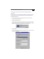
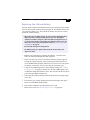
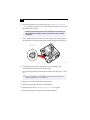
Accessing the BIOS Setup Utility............................................................16
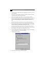
Changing the Display's Power Management Settings.........................17
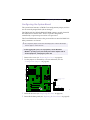
Configuring the System Board ...............................................................19

VAIO Digital Studio™ Reference Manual
xii
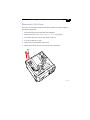
Chapter 3 — Removing, Installing, and Replacing
Components
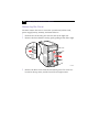
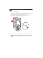
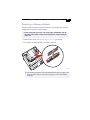
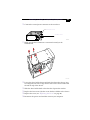
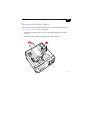
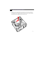
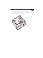
Removing the Cover ................................................................................22
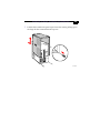
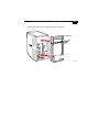
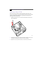
Removing the Front Panel .......................................................................24
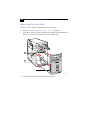
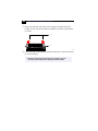
Replacing the Front Panel........................................................................25
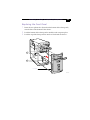
Replacing the Cover .................................................................................26
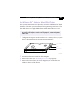
Installing an Add-In Card .......................................................................28
Removing an Add-in Card .....................................................................29
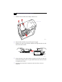
Replacing the Lithium Battery ...............................................................31
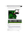
Installing System Memory ......................................................................34
Removing a Memory Module ................................................................37
Removing a Slot Cover.............................................................................39
Covering an Open I/O Slot ....................................................................40
Installing a 3½” Internal Hard Disk Drive ............................................41
Removing the Power Supply...................................................................45
Replacing the Power Supply ...................................................................48
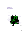
Chapter 4 — System Board
Connectors..................................................................................................50
Front Panel Header (J25)...................................................................50
Diskette Drive Connector ................................................................51
Memory Module (DIMM) Connectors ...........................................52
PCI Slot Connectors...........................................................................53
AGP Connector ..................................................................................54
IDE Connectors .................................................................................55
Power Connector ...............................................................................55
Keyboard and Mouse Connectors ..................................................56
USB Connectors .................................................................................57
Ethernet Connector ...........................................................................58
Serial 1, Printer, and i.LINK Connectors ........................................59
Fan Connectors ..................................................................................61
Game Connector.................................................................................62
Headphones, Line In, Mic Connectors............................................63
i.LINK Header Connectors...............................................................64
CD-IN Connector ...............................................................................65
AUX-IN Connector............................................................................66
Configuration Jumpers ............................................................................67

xiii
Chapter 5 — Fax/Modem Card
Connectors .................................................................................................69
Chapter 6 — Video Card
Chapter 7 — CMOS Setup Options
Main Screen ...............................................................................................75
Advanced Screen ......................................................................................77
Power Screen..............................................................................................83
Boot Screen ................................................................................................85
Exit Screen..................................................................................................86
Chapter 8 — Miscellaneous Technical Information
About User and Supervisor Passwords ................................................88
Beep Code Error Messages .....................................................................89
PCI Configuration Status and Error Messages ....................................90
DMA Channel Assignments ...................................................................92
System I/O Address Map ......................................................................93
Memory Map ...........................................................................................95
Chapter 9 — Specifications
Processors .................................................................................................97
Chipset ......................................................................................................97
AGP Bus .....................................................................................................97
PCI Bus ......................................................................................................97
Memory Modules (DIMMs) ..................................................................97
DIMM Configurations .............................................................................98
L2 Cache ....................................................................................................98
Graphics ....................................................................................................98
Audio .........................................................................................................98
Communications .....................................................................................99
I/O and Expansion Slots .........................................................................99
Drives and Controllers ..........................................................................100
System BIOS ...........................................................................................100

xiv

1
Chapter 1
Identifying Components
The following sections identify and describe each component that is
visible from the exterior of the VAIO Digital Studio™ Computer. Internal
components are identified in the appropriate section of this manual.

VAIO Digital Studio Reference Manual
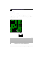
2
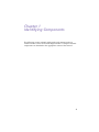
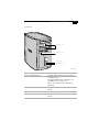
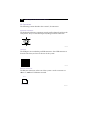
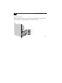
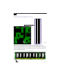
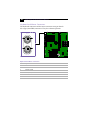
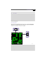
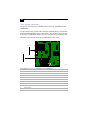
Front View
Front panel
OM04694X.VSD

Identifying Components
3
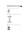
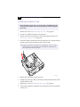
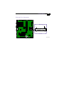
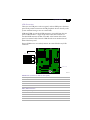
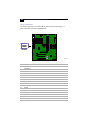
Drives
Drive Description
Diskette drive 3.5-inch, 1.44 Mbyte.
DVD-ROM drive
*
* Data on a DVD-ROM is read at a variable transfer rate, ranging from 6.6X at the innermost track to 16X at
the outermost track (the data transfer standard 1X rate is 1385 kbytes/s). The average data transfer rate is
11.3X (15,255 kbytes/s). Data on a CD-ROM is read at a variable transfer rate, ranging from 17.2X at the
innermost track to 40X at the outermost track (the data transfer standard 1X rate is 150 kbytes/s). The
average data transfer rate is 28.6X (4293 kbytes/s).
DVD-ROM read: 16X (maximum performance).
CD-ROM read: 40X (maximum performance).
CD-RW drive
†
† CD-RW writing speed may vary, depending on the media. The maximum writing speed is 8X (1X = 150
kbytes/s). The maximum reading speed is 20X.
CD-RW read: 20X (maximum performance).
CD-RW write: 4X (maximum performance).
CD-R read: 32X (maximum performance).
CD-R write: 8X (maximum performance).
CD-ROM read: 32X (maximum performance).
FRNTPNLA.VSD
DVD-ROM
CD-RW
Diskette drive

VAIO Digital Studio Reference Manual
4
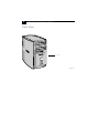
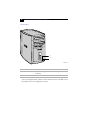
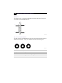
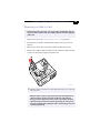
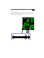
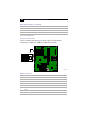
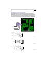
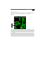
Buttons and Switches
Button or switch Description
Power/Standby switch Turns system power on, off, or into standby mode.
Diskette eject button Ejects a diskette.
Optical disc eject button
Automatically opens and closes the optical drive
tray.
FRNTPNLB.VSD
Optical disc eject
Diskette eject
Power/Standby

Identifying Components
5
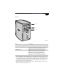
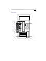
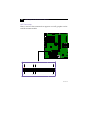
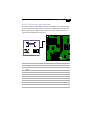
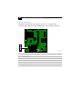
Indicators
Indicator Description
Power/Standby indicator Standby (amber) indicates the computer is
in standby mode.
On (green) indicates the computer is out
of standby mode, ready to use.
Off (no color) indicates the computer is
turned off.
Diskette drive access indicator On (green) indicates diskette drive
activity.
Optical drive access indicator On (orange) indicates CD-ROM activity.
Hard disk drive access indicator On (amber) indicates hard disk drive
activity.
FRNTPNLC.VSD
Optical drive access
Diskette drive access
Power/Standby
Hard disk drive access

VAIO Digital Studio Reference Manual
6
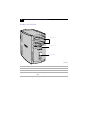
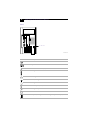
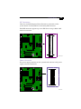
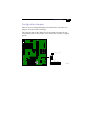
Connectors
Connector Description
i.LINK
®
(IEEE-1394)
*
* To connect to a 6-pin i.LINK device, use the i.LINK connector on the back of the system. A 6-pin i.LINK
connector can supply power from the computer to the device if the device also has a 6-pin i.LINK connector.
A 4-pin i.LINK connector cannot supply power to the device.
Connects to a digital device that has a 4-pin i.LINK
connector.
USB Connects to USB devices.
FRNTPNLD.VSD
USB
i.LINK
La page charge ...
La page charge ...
La page charge ...
La page charge ...
La page charge ...
La page charge ...
La page charge ...
La page charge ...
La page charge ...
La page charge ...
La page charge ...
La page charge ...
La page charge ...
La page charge ...
La page charge ...
La page charge ...
La page charge ...
La page charge ...
La page charge ...
La page charge ...
La page charge ...
La page charge ...
La page charge ...
La page charge ...
La page charge ...
La page charge ...
La page charge ...
La page charge ...
La page charge ...
La page charge ...
La page charge ...
La page charge ...
La page charge ...
La page charge ...
La page charge ...
La page charge ...
La page charge ...
La page charge ...
La page charge ...
La page charge ...
La page charge ...
La page charge ...
La page charge ...
La page charge ...
La page charge ...
La page charge ...
La page charge ...
La page charge ...
La page charge ...
La page charge ...
La page charge ...
La page charge ...
La page charge ...
La page charge ...
La page charge ...
La page charge ...
La page charge ...
La page charge ...
La page charge ...
La page charge ...
La page charge ...
La page charge ...
La page charge ...
La page charge ...
La page charge ...
La page charge ...
La page charge ...
La page charge ...
La page charge ...
La page charge ...
La page charge ...
La page charge ...
La page charge ...
La page charge ...
La page charge ...
La page charge ...
La page charge ...
La page charge ...
La page charge ...
La page charge ...
La page charge ...
La page charge ...
La page charge ...
La page charge ...
La page charge ...
La page charge ...
La page charge ...
La page charge ...
La page charge ...
La page charge ...
La page charge ...
La page charge ...
La page charge ...
La page charge ...
La page charge ...
La page charge ...
La page charge ...
La page charge ...
-
 1
1
-
 2
2
-
 3
3
-
 4
4
-
 5
5
-
 6
6
-
 7
7
-
 8
8
-
 9
9
-
 10
10
-
 11
11
-
 12
12
-
 13
13
-
 14
14
-
 15
15
-
 16
16
-
 17
17
-
 18
18
-
 19
19
-
 20
20
-
 21
21
-
 22
22
-
 23
23
-
 24
24
-
 25
25
-
 26
26
-
 27
27
-
 28
28
-
 29
29
-
 30
30
-
 31
31
-
 32
32
-
 33
33
-
 34
34
-
 35
35
-
 36
36
-
 37
37
-
 38
38
-
 39
39
-
 40
40
-
 41
41
-
 42
42
-
 43
43
-
 44
44
-
 45
45
-
 46
46
-
 47
47
-
 48
48
-
 49
49
-
 50
50
-
 51
51
-
 52
52
-
 53
53
-
 54
54
-
 55
55
-
 56
56
-
 57
57
-
 58
58
-
 59
59
-
 60
60
-
 61
61
-
 62
62
-
 63
63
-
 64
64
-
 65
65
-
 66
66
-
 67
67
-
 68
68
-
 69
69
-
 70
70
-
 71
71
-
 72
72
-
 73
73
-
 74
74
-
 75
75
-
 76
76
-
 77
77
-
 78
78
-
 79
79
-
 80
80
-
 81
81
-
 82
82
-
 83
83
-
 84
84
-
 85
85
-
 86
86
-
 87
87
-
 88
88
-
 89
89
-
 90
90
-
 91
91
-
 92
92
-
 93
93
-
 94
94
-
 95
95
-
 96
96
-
 97
97
-
 98
98
-
 99
99
-
 100
100
-
 101
101
-
 102
102
-
 103
103
-
 104
104
-
 105
105
-
 106
106
-
 107
107
-
 108
108
-
 109
109
-
 110
110
-
 111
111
-
 112
112
-
 113
113
-
 114
114
-
 115
115
-
 116
116
-
 117
117
-
 118
118


Sony PCV-R556DS Guide de référence
- Catégorie
- Des cahiers
- Taper
- Guide de référence
- Ce manuel convient également à
dans d''autres langues
- English: Sony PCV-R556DS Reference guide
Documents connexes
-
Sony PCV-RX640 Guide de référence
-
Sony PCV-J200 Guide de référence
-
Sony PCV-RX540 Guide de référence
-
-
-
-
-
Sony VAIO VGP-UPR1 Manuel utilisateur
-
-
Sony PCG-TR3A Guide de démarrage rapide
Autres documents
-
Acer Aspire 1602M Guide d'installation
-
Gigabyte GS-SR125ED Guide d'installation
-
Creative Blaster Modem Getting Started
-
Dynex DX-MIDTWER Manuel utilisateur
-
 Jou Jye Computer A 2434 Fiche technique
-
Lindy 2 Port Serial & 1 Port Parallel Low Profile Card, PCI Manuel utilisateur
-
SDI Riva Star Immediately Relieves Tooth Sensitivity Mode d'emploi
-
Accton Technology USB Ethernet Adapter Manuel utilisateur
