Miller IHPS II RACK Le manuel du propriétaire
- Catégorie
- Système de soudage
- Taper
- Le manuel du propriétaire
Ce manuel convient également à

IHPS II Rack
Processes
Description
OM-191 152A
September 2000
Induction Heating
Induction Heating Power Source Rack

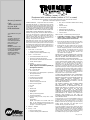
Miller Electric manufactures a full line
of welders and welding related equipment.
For information on other quality Miller
products, contact your local Miller distributor
to receive the latest full line catalog or
individual catalog sheets. To locate your nearest
distributor or service agency call 1-800-4-A-Miller,
or visit us at www.MillerWelds.com on the web.
Thank you and congratulations on choosing Miller. Now
you can get the job done and get it done right. We know
you don’t have time to do it any other way.
That’s why when Niels Miller first started building arc
welders in 1929, he made sure his products offered
long-lasting value and superior quality. Like you, his
customers couldn’t afford anything less. Miller products
had to be more than the best they could be. They had to
be the best you could buy.
Today, the people that build and sell Miller products continue the
tradition. They’re just as committed to providing equipment and service
that meets the high standards of quality and value established in 1929.
This Owner’s Manual is designed to help you get the most out of your
Miller products. Please take time to read the Safety precautions. They will
help you protect yourself against potential hazards on the worksite. We’ve
made installation and operation quick and easy.
With Miller you can count on years of reliable
service with proper maintenance. And if for
some reason the unit needs repair, there’s a
Troubleshooting section that will help you
figure out what the problem is. The parts list
will then help you to decide which exact part
you may need to fix the problem. Warranty and
service information for your particular model
are also provided.
Miller is the first welding
equipment manufacturer in
the U.S.A. to be registered to
the ISO 9001 Quality System
Standard.
Working as hard as you do
– every power source from
Miller is backed by the most
hassle-free warranty in the
business.
From Miller to You
Miller offers a Technical
Manual which provides
more detailed service and
parts information for your
unit. To obtain a Technical
Manual, contact your local
distributor. Your distributor
can also supply you with
Welding Process Manuals
such as SMAW, GTAW,
GMAW, and GMAW-P.

TABLE OF CONTENTS
SECTION 1 – SAFETY PRECAUTIONS – READ BEFORE USING 1. . . . . . . . . . . . . . . . . . . . . . . . . . .
1-1. Symbol Usage 1. . . . . . . . . . . . . . . . . . . . . . . . . . . . . . . . . . . . . . . . . . . . . . . . . . . . . . . . . . . . . . . .
1-2. Induction Heating Hazards 1. . . . . . . . . . . . . . . . . . . . . . . . . . . . . . . . . . . . . . . . . . . . . . . . . . . . .
1-3. Additional Symbols for Installation, Operation, and Maintenance 2. . . . . . . . . . . . . . . . . . . . . .
1-4. Principal Safety Standards 2. . . . . . . . . . . . . . . . . . . . . . . . . . . . . . . . . . . . . . . . . . . . . . . . . . . . .
1-5. EMF Information 2. . . . . . . . . . . . . . . . . . . . . . . . . . . . . . . . . . . . . . . . . . . . . . . . . . . . . . . . . . . . . .
SECTION 1 – MESURES DE SECURITE POUR LE CHAUFFAGE PAR INDUCTION 3. . . . . . . . . . . .
1-1. Dangers supplémentaires de mise en route, de fonctionnement et d’entretien 4. . . . . . . . . . .
1-2. Informations concernant les champs électro-magnétiques (Information EMF) 4. . . . . . . . . . .
1-3. Principales normes de sécurité 4. . . . . . . . . . . . . . . . . . . . . . . . . . . . . . . . . . . . . . . . . . . . . . . . . .
SECTION 2 – INSTALLATION 5. . . . . . . . . . . . . . . . . . . . . . . . . . . . . . . . . . . . . . . . . . . . . . . . . . . . . . . . . . .
2-1. Specifications 5. . . . . . . . . . . . . . . . . . . . . . . . . . . . . . . . . . . . . . . . . . . . . . . . . . . . . . . . . . . . . . . .
2-2. Rack Assembly Procedure 5. . . . . . . . . . . . . . . . . . . . . . . . . . . . . . . . . . . . . . . . . . . . . . . . . . . . .
2-3. Selecting A Location And Moving Rack 6. . . . . . . . . . . . . . . . . . . . . . . . . . . . . . . . . . . . . . . . . . .
2-4. Installing 3-Phase Twistlock Plug Onto Input Power Cord And Connecting To
Power Distribution Box 7. . . . . . . . . . . . . . . . . . . . . . . . . . . . . . . . . . . . . . . . . . . . . . . . . . . . . . . . .
2-5. Positioning Jumper Links In Power Source (IHPS II 5 KW Units Only) 8. . . . . . . . . . . . . . . . .
2-6. Installing Disconnect Switch, Power Source And Controller Onto Rack 9. . . . . . . . . . . . . . . . .
2-7. Connecting To 120 Volts AC Duplex Receptacle 10. . . . . . . . . . . . . . . . . . . . . . . . . . . . . . . . . . . .
2-8. Positioning Jumper Links In Rack (230 Or 460 VAC Unit Only) 11. . . . . . . . . . . . . . . . . . . . . . .
2-9. Connecting Input Power To Rack 12. . . . . . . . . . . . . . . . . . . . . . . . . . . . . . . . . . . . . . . . . . . . . . . .
2-10. Electrical Service Requirements 12. . . . . . . . . . . . . . . . . . . . . . . . . . . . . . . . . . . . . . . . . . . . . . . . .
SECTION 3 – MAINTENANCE & TROUBLESHOOTING 13. . . . . . . . . . . . . . . . . . . . . . . . . . . . . . . . . . . .
3-1. Routine Maintenance 13. . . . . . . . . . . . . . . . . . . . . . . . . . . . . . . . . . . . . . . . . . . . . . . . . . . . . . . . . .
3-2. Fuses F1 And F2 13. . . . . . . . . . . . . . . . . . . . . . . . . . . . . . . . . . . . . . . . . . . . . . . . . . . . . . . . . . . . .
3-3. Circuit Breakers 14. . . . . . . . . . . . . . . . . . . . . . . . . . . . . . . . . . . . . . . . . . . . . . . . . . . . . . . . . . . . . .
3-4. Troubleshooting 15. . . . . . . . . . . . . . . . . . . . . . . . . . . . . . . . . . . . . . . . . . . . . . . . . . . . . . . . . . . . . .
SECTION 4 – ELECTRICAL DIAGRAMS 16. . . . . . . . . . . . . . . . . . . . . . . . . . . . . . . . . . . . . . . . . . . . . . . . .
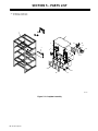
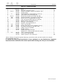
SECTION 5 – PARTS LIST 20. . . . . . . . . . . . . . . . . . . . . . . . . . . . . . . . . . . . . . . . . . . . . . . . . . . . . . . . . . . . . .
WARRANTY
OM-191 152A


OM-191 152 Page 1
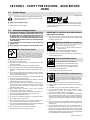
SECTION 1 – SAFETY PRECAUTIONS – READ BEFORE
USING
1-1. Symbol Usage
safety_ihom 5/98
Means Warning! Watch Out! There are possible hazards
with this procedure! The possible hazards are shown in
the adjoining symbols.
Y Marks a special safety message.
. Means “Note”; not safety related.
This group of symbols means Warning! Watch Out! possible
ELECTRIC SHOCK, MOVING PARTS, and HOT PARTS hazards.
Consult symbols and related instructions below for necessary actions
to avoid the hazards.
1-2. Induction Heating Hazards
Y The symbols shown below are used throughout this manual to
call attention to and identify possible hazards. When you see
the symbol, watch out, and follow the related instructions to
avoid the hazard. The safety information given below is only
a summary of the more complete safety information found in
the Safety Standards listed in Section 1-4. Read and follow all
Safety Standards.
Y Only qualified persons should install, operate, maintain, and
repair this unit.
Y During operation, keep everybody, especially children, away.
ELECTRIC SHOCK can kill.
Touching live electrical parts can cause fatal shocks
or severe burns. The power circuit and output bus
bars or connections are electrically live whenever
the output is on. The input power circuit and machine
internal circuits are also live when power is on. Incorrectly installed or
improperly grounded equipment is a hazard.
D Do not touch live electrical parts.
D Enclose any connecting bus bars and coolant fittings to prevent
unintentional contact.
D Wear dry, hole-free insulating gloves and body protection.
D Insulate yourself from work and ground using dry insulating mats or
covers big enough to prevent any physical contact with the work or
ground.
D Disconnect input power before installing or servicing this equip-
ment. Lockout/tagout input power according to OSHA 29 CFR
1910.147 (see Safety Standards).
D Use only nonconductive coolant hoses with a minimum length of 18
inches (457 mm) to provide isolation.
D Properly install and ground this equipment according to its Owner’s
Manual and national, state, and local codes.
D Always verify the supply ground – check and be sure that input pow-
er cord ground wire is properly connected to ground terminal in
disconnect box or that cord plug is connected to a properly
grounded receptacle outlet.
D When making input connections, attach proper grounding
conductor first – double-check connections.
D Frequently inspect input power cord for damage or bare wiring – re-
place cord immediately if damaged – bare wiring can kill.
D Turn off all equipment when not in use.
D Do not use worn, damaged, undersized, or poorly spliced cables.
D Do not drape cables over your body.
D Do not touch power circuit if you are in contact with the work,
ground, or another power circuit from a different machine.
D Use only well-maintained equipment. Repair or replace damaged
parts at once. Maintain unit according to manual.
D Wear a safety harness if working above floor level.
D Keep all panels and covers securely in place.
SIGNIFICANT DC VOLTAGE exists after removal of
input power on inverters.
D Turn Off inverter, disconnect input power, and discharge input
capacitors according to instructions in Maintenance Section before
touching any internal parts.
INDUCTION HEATING can cause burns.
D Hot parts and equipment can injure.
D Do not touch or handle induction head/coil
during operation.
D Do not touch hot parts bare-handed.
D Allow cooling period before handling parts or equipment.
D Keep metal jewelry and other metal personal items away from
head/coil during operation.
FIRE OR EXPLOSION hazard.
D Do not overheat parts and adhesive.
D Watch for fire; keep extinguisher nearby.
D Keep flammables away from work area.
D Do not locate unit on, over, or near combustible surfaces.
D Do not install unit near flammables.
D Do not operate unit in explosive atmosphere.
Induction Heating of certain materials, adhesives,
and fluxes can produce fumes and gases. Breathing
these fumes and gases can be hazardous to your
health.
FUMES AND GASES can be hazardous.
D Keep your head out of the fumes. Do not breathe the fumes.
D If inside, ventilate the area and/or use exhaust to remove fumes
and gases.
D If ventilation is poor, use an approved air-supplied respirator.
D Read the Material Safety Data Sheets (MSDSs) and the
manufacturer’s instruction for adhesives, fluxes, metals,
consumables, coatings, cleaners, and degreasers.
D Work in a confined space only if it is well ventilated, or while wearing
an air-supplied respirator. Always have a trained watchperson
nearby. Fumes and gases from heating can displace air and lower
the oxygen level causing injury or death. Be sure the breathing air is
safe.
D Do not heat in locations near degreasing, cleaning, or spraying op-
erations. The heat can react with vapors to form highly toxic and
irritating gases.
D Do not overheat coated metals, such as galvanized, lead, or
cadmium plated steel, unless the coating is removed from the
heated area, the area is well ventilated, and if necessary, while
wearing an air-supplied respirator. The coatings and any metals
containing these elements can give off toxic fumes if overheated.
See coating MSDS for temperature information.

OM-191 152 Page 2
1-3. Additional Symbols for Installation, Operation, and Maintenance
FALLING UNIT can cause injury.
D Use handle and have person of adequate
physical strength lift unit.
D Move unit with hand cart or similar device.
D For units without a handle, use equipment of
adequate capacity to lift unit.
D When using lift forks to move unit, be sure forks are long enough
to extend beyond opposite side of unit.
FLYING METAL OR ADHESIVE can injure eyes.
D Wear approved safety glasses with side
shields or wear face shield.
MOVING PARTS can cause injury.
D Keep away from moving parts such as fans.
D Keep all doors, panels, covers, and guards
closed and securely in place.
MAGNETIC FIELDS can affect pacemakers.
D Pacemaker wearers keep away.
D Wearers should consult their doctor before
going near induction heating operations.
OVERUSE can cause OVERHEATING
D Allow cooling period.
D Reduce output or reduce duty cycle before
starting to heat again.
D Follow rated duty cycle.
STATIC (ESD) can damage PC boards.
D Put on grounded wrist strap BEFORE handling
boards or parts.
D Use proper static-proof bags and boxes to
store, move, or ship PC boards.
H.F. RADIATION can cause interference.
D High-frequency (H.F.) can interfere with radio
navigation, safety services, computers, and
communications equipment.
D Have only qualified person familiar with electronic equipment per-
form this installation.
D The user is responsible for having a qualified electrician promptly
correct any interference problem resulting from the installation.
D If notified by the FCC about interference, stop using the equip-
ment at once.
D Have the installation regularly checked and maintained.
D Keep high-frequency source doors and panels tightly shut.
1-4. Principal Safety Standards
Safety and Health Standards, OSHA 29 CFR 1910, from Superinten-
dent of Documents, U.S. Government Printing Office, Washington, D.C.
20402.
National Electrical Code, NFPA Standard 70, from National Fire Protec-
tion Association, Batterymarch Park, Quincy, MA 02269.
Canadian Electrical Code Part 1, CSA Standard C22.1, from Canadian
Standards Association, Standards Sales, 178 Rexdale Boulevard,Rex-
dale, Ontario, Canada M9W 1R3.
Safe Practices For Occupation And Educational Eye And Face Protec-
tion, ANSI Standard Z87.1, from American National Standards Institute,
1430 Broadway, New York, NY 10018.
1-5. EMF Information
Considerations About Induction Heating And The Effects Of Low Fre-
quency Electric And Magnetic Fields
The following is a quotation from the General Conclusions Section of the
U.S. Congress, Office of Technology Assessment, Biological Effects of
Power Frequency Electric & Magnetic Fields – Background Paper,
OTA-BP-E-53 (Washington, DC: U.S. Government Printing Office, May
1989): “. . . there is now a very large volume of scientific findings based
on experiments at the cellular level and from studies with animals and
people which clearly establish that low frequency magnetic fields can
interact with, and produce changes in, biological systems. While most of
this work is of very high quality, the results are complex. Current scientif-
ic understanding does not yet allow us to interpret the evidence in a
single coherent framework. Even more frustrating, it does not yet allow
us to draw definite conclusions about questions of possible risk or to of-
fer clear science-based advice on strategies to minimize or avoid
potential risks.”
To reduce magnetic fields in the workplace, use the following proce-
dures:
1. Arrange output cable to one side and away from the operator.
2. Do not coil or drape output cable around the body.
3. Keep power source and cable as far away from the operator as
practical.
About Pacemakers:
The above procedures are also recommended for pacemaker wearers.
Consult your doctor for complete information.

OM-191 152 Page 3
SECTION 1 – MESURES DE SECURITE POUR LE
CHAUFFAGE PAR INDUCTION
safetyihom_fre 9/96
PRENDRE LES MESURES NECESSAIRES POUR EVITER LES RISQUES DE BLESSURES GRAVES, VOIRE
MORTELLES. TENIR LES ENFANTS A DISTANCE. LES PORTEURS D’UN STIMULATEUR CARDIAQUE DOIVENT
PREALABLEMENT CONSULTER LEUR MEDECIN.
Pendant les opérations de chauffage, comme dans la plupart des activités, l’opérateur s’expose à certains dangers.
Le chauffage n’est pas dangereux à condition de prendre certaines mesures. Les consignes de sécurité indiquées
ci-après ne sont qu’un résumé des informations plus détaillées se trouvant dans les normes de sécurité énumérées
à la page suivante. Lire et respecter toutes les normes de sécurité.
LES OPERATIONS D’INSTALLATION, DE FONCTIONNEMENT, DE MAINTENANCE ET DE REPARATION NE DOIVENT
ETRE CONFIEES QU’A DU PERSONNEL QUALIFIE.
LE CHAUFFAGE PAR INDUCTION peut être dangereux.
AVERTISSEMENT
Danger de mort PAR
ELECTROCUTION.
Le contact de composants électriques peut
provoquer des accidents mortels ou des brûlures
graves. Le circuit électrique est sous tension lorsque
le courant est délivré à la sortie. Le circuit
d’alimentation et les circuits internes de la machine
sont également sous tension lorsque l’alimentation
est sur marche. Des équipements installés ou reliés à
la borne de terre de manière incorrecte sont
dangereux.
1. Ne pas toucher des composants électriques sous tension.
2. Porter des gants d’isolation secs, sans trous, et une protection
corporelle.
3. Isolez-vous de la pièce et du sol avec des tapis ou des
couvertures d’isolation suffisamment grands pour prévenir tout
contact physique avec la pièce ou la terre.
4. Déconnecter l’alimentation avant d’installer l’appareil ou d’en
effectuer l’entretien. Verrouiller ou étiqueter la sortie
d’alimentation selon la norme OSHA 29 CFR 1910.147
(se reporter aux Principales normes de sécurité).
5. Installer et mettre cet équipement correctement à la terre
conformément au manuel utilisateur et aux codes nationaux,
gouvernementaux et locaux.
6. Vérifier souvent la terre de l’alimentation – contrôler et s’assurer
que le conducteur de terre du câble d’alimentation est
correctement relié à la borne de terre dans le boîtier de
déconnexion ou que le connecteur est branché à une sortie de
boîtier correctement mise à la terre.
7. En réalisant des connexions d’entrée brancher d’abord le
conducteur de terre approprié – contrôler deux fois les
connexions.
8. Vérifier souvent le bon état du câble d’alimentation ou l’isolation
des fils – remplacer le câble immédiatement s’il est endommagé
– des fils dénudés peuvent provoquer des accidents mortels.
9. Arrêter tous les équipements lorsqu’ils ne sont pas utilisés.
10. Ne pas utiliser des câbles usés, endommagés,
sousdimensionnés ou mal épissés.
11. Ne pas porter les câbles autour de votre corps.
12. Ne pas toucher le circuit électrique si vous êtes en contact avec la
pièce, la terre ou le circuit électrique d’une autre machine.
13. Utiliser seulement des équipements bien entretenus. Réparer ou
remplacer immédiatement des composants endommagés.
Effectuer des travaux d’entretien sur l’appareil selon le manuel.
14. Porter un harnais de sécurité pour effectuer des travaux
au-dessus du sol.
15. Maintenir solidement en place tous les panneaux et couvercles.
LE CHAUFFAGE PAR INDUCTION peut
provoquer des blessures ou des
brûlures au contact de PIECES
CHAUDES OU DE L’EQUIPEMENT.
1. Ne pas toucher ou manipuler la tête/l’enroulement à induction
pendant le fonctionnement.
2. Tenir les bijoux et autres objets personnels en métal éloignés de
la tête/de l’enroulement pendant le fonctionnement.
3. Laisser refroidir les composants ou équipements avant de les
manipuler.
LE CHAUFFAGE PAR INDUCTION peut
provoquer un incendie.
1. Ne pas surchauffer les composants ni les
adhésifs.
2. Attention aux risques d’incendie: tenir un
extincteur à proximité.
3. Stocker des produits inflammables hors de la
zone de travail.
La mise en place de l’appareil sur, au-dessus ou à
proximité de surfaces inflammables peut être source
d’INCENDIES OU d’EXPLOSION.
1. Ne pas placer l’appareil sur, au-dessus ou à proximité de
surfaces infllammables.
2. Ne pas installer l’appareil à proximité de produits inflammables
3. Ne pas faire fonctionner l’appareil en atmosphère explosive.
DES FUMEES ET DES GAZ peuvent
être dangereux pour votre santé.
Le chauffage à induction génère des fumées et des
gaz. Leur inhalation peut être dangereuse pour votre
santé.
1. Eloigner la tête des fumées. Ne pas respirer les fumées.
2. A l’interieur, ventiler la zone et/ou utiliser un extracteur pour
l’évacuation des fumées et des gaz.
3. Si la ventilation est insuffisante, utiliser un respirateur à
alimentation d’air homologué.
4. Lire les spécifications de sécurité des matériaux (MSDSs) et les
instructions du fabricant concernant les adhésifs, les métaux, les
consommables, les revêtements, les nettoyants et les
dégraisseurs.
5. Travailler dans un espace fermé seulement s’il est bien ventilé ou
en portant un respirateur. Demander toujours à un surveillant
dûment formé de se tenir à proximité. Des fumées et des gaz
provenant du chauffage peuvent déplacer l’air, abaisser le niveau
d’oxygène, et provoquer des lésions ou des accidents mortels.
S’assurer que l’air ambiant ne présente aucun danger.
6. Ne pas chauffer dans des endroits se trouvant à proximité
d’opérations de dégraissage, de nettoyage ou de pulvérisation. La
chaleur peut réagir en présence de vapeurs et former des gaz
hautement toxiques et irritants.
7. Ne pas chauffer des métaux munis d’un revêtement tels que l’acier
galvanisé, plaqué au plomb ou au cadmium, à moins que le
revêtement ne soit enlevé de la zone chauffée, que la zone soit
bien ventilée et, si nécessaire, en portant un respirateur. Les
revêtements et tous les métaux contenant ces éléments peuvent
dégager des fumées toxiques s’ils sont chauffés.

OM-191 152 Page 4
1-1. Dangers supplémentaires de mise en route, de fonctionnement et d’entretien
LA CHUTE DE MATERIEL peut provoquer
des blessures personnelles graves et en-
dommager les équipements.
1. Utiliser la poignée et demander à une personne
ayant la force physique nécessaire pour soulever
l’appareil.
2. Déplacer l’appareil à l’aide d’un charriot ou d’un
engin similaire.
3. Pour les appareils sans poignée utiliser un équipe-
ment d’une capacité appropriée pour soulever
l’appareil.
4. En utilisant des fourches de levage pour déplacer
l’unité, s’assurer que les fourches sont suffisamment
longues pour dépasser du côté opposé de l’appareil.
LA PROJECTION DE PIECES DE METAL ou
DE COLLE peut provoquer des blessures
aux yeux.
1. Porter des lunettes de protection avec des protec-
tions latérales.
DES ORGANES MOBILES peuvent
provoquer des blessures.
1. S’abstenir de toucher des organes mobiles tels que
des ventilateurs.
2. Maintenir fermés et fixement en place les portes, pan-
neaux, recouvrements et dispositifs de protection.
DES CHAMPS MAGNETIQUES CREES PAR
DES COURANTS ELEVES peuvent affecter le
fonctionnement du stimulateur cardiaque.
1. Porteurs de stimulateur cardiaque, restez à distance.
2. Les porteurs d’un stimulateur cardiaque doivent d’a-
bord consulter leur médecin avant de s’approcher
des opérations de chauffage à induction.
UNE UTILISATION INTENSIVE peut provo-
quer un SURCHAUFFEMENT DU MATERIEL.
1. Prévoir une période de refroidissement
2. Réduire le courant de sortie ou le facteur de marche
avant de recommencer le chauffage.
3. Respecter le facteur de marche nominal.
L’ELECTRICITE STATIQUE peut endomma-
ger les composants des tableaux électri-
ques.
1. Etablir la connexion avec la barrette de terre avant
de manipuler des cartes ou des pièces.
2. Utiliser des pochettes et des boîtes antistatiques
pour stocker, déplacer ou expédier des cartes PC.
Il subsiste DU COURANT CONTINU IMPOR-
TANT après la mise hors tension de l’alimen-
tation électrique.
1. Avant de toucher des organes internes, arrêter la
source électrique, débrancher l’alimentation, et dé-
charger les condensateurs d’alimentation conformé-
ment aux instructions indiquées dans la partie main-
tenance.
LE RAYONNEMENT HAUTE FREQUENCE
peut provoquer des interférences avec les
équipements de radio-navigation et de com-
munication, les services de sécurité et les or-
dinateurs.
• Demander seulement à des personnes qualifiées
familiarisées avec des équipements électroniques
de faire fonctionner l’installation.
• L’utilisateur est tenu de faire corriger rapidement par
un électricien qualifié les interférences résultant de
l’installation.
• Si le FCC signale des interférences, arrêter immé-
diatement l’appareil.
• Effectuer régulièrement le contrôle et l’entretien de
l’installation.
• Maintenir soigneusement fermés les portes et les
panneaux des sources de haute fréquence.
1-2. Informations concernant les champs électro-magnétiques (Information EMF)
Considérations relatives au chauffage à induction et aux effets des
champs électriques et magnétiques basse fréquence.
Le texte suivant est extrait des conclusions générales Département
du Congrès U.S., Office of Technology Assessment, Effets
biologiques des champs magnétiques et électriques basse
fréquence – Background Paper, OTA-BP-E-53 (Washington, DC:
U.S. Government Printing Office, May 1989): “. . . on dispose
maintenant d’importantes découvertes scientifiques reposant sur
des expériences effectuées dans le domaine cellulaire et des études
réalisées sur des animaux et des personnes qui démontrent
clairement que des champs magnétiques basse fréquence peuvent
avoir une interaction et produire des changements dans les
systèmes biologiques. Alors que la plus grande partie de cet ouvrage
est d’une très grande qualité, les résultats sont complexes. La
compréhension scientifique courante ne nous permet pas encore
d’interpréter la preuve fournie dans un seul ouvrage cohérent. Il est
encore plus frustrant de ne pas pouvoir tirer des conclusions
définitives en ce qui concerne les problèmes de risque possible ou de
proposer des recommandations scientifiques claires pour des
stratégies à suivre en vue de minimiser ou de prévenir des risques
potentiels.”
Pour réduire les champs magnétiques sur le poste de travail,
appliquer les procédures suivantes :
4. Disposer le câble de sortie d’un côté à distance de l’opérateur
5. Ne pas enrouler ou draper le câble électrique autour du corps.
6. Placer la source de courant et le câble le plus loin possible de
l’opérateur.
En ce qui concerne les stimulateurs cardiaques
Les procédures ci-dessus concernent également les porteurs de
stimulateur cardiaque. Consulter votre médecin pour un complément
d’information.
1-3. Principales normes de sécurité
Normes de sécurité et de santé, OSHA 29 CFR 1910, from
Superintendent of Documents, U.S. Government Printing Office,
Washington, D.C. 20402.
Code électrique national, NFPA Standard 70, from National Fire
Protection Association, Batterymarch Park, Quincy, MA 02269.
Code électrique du Canada, partie 1, CSA Standard C22.1, from
Canadian Standards Association, Standards Sales, 178 Rexdale
Boulevard,Rexdale, Ontario, Canada M9W 1R3.
Safe Practices For Occupation And Educational Eye And Face
Protection, ANSI Standard Z87.1, from American National Standards
Institute, 1430 Broadway, New York, NY 10018.

OM-191 152 Page 5
SECTION 2 – INSTALLATION
2-1. Specifications
Required
Input Power
Required Induction Heat-
ing Power Source
Capacity Overall Dimensions Weight
230 Or 460 Volts AC;
50/60 Hz; Three-Phase
IHPS II 5 KW Or IHPS II 10 DC
Requiring 230 Or 460 Volts
Input Power
8 Induction Heating
Power Sources
Height: 61 in (1549 mm );
Width: 32-1/4 in
(819 mm);
Depth: 32-1/4 in (819 mm)
Net: 250 lb (113 kg)
400 Volts AC; 50/60 Hz;
Three-Phase
IHPS II 4 KW Requiring 400
Volts Input Power
8 Induction Heating
Power Sources
Height: 61 in (1549 mm );
Width: 32-1/4 in
(819 mm);
Depth: 32-1/4 in (819 mm)
Net: 250 lb (113 kg)
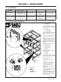
2-2. Rack Assembly Procedure
Ref. 802 203 / Ref. 802 204
1 Side Member (8)
2 Access Hole
All side members have access
holes for tightening cross member
securing bolts.
3 Cross Member (14)
4 Securing Bolt (36)
Install a securing bolt into each end
of cross members and side mem-
bers.
Install cross members to side mem-
bers, but do not tighten securing
bolts.
Install side member/cross member
assemblies to uprights. First, tight-
en side members to uprights, then
tighten cross members to side
members.
Install and secure remaining cross
members to uprights.
5 End Cap w/Hole (4)
6 Leveling Foot (4)
7 Upright (4 )
Install end cap and leveling foot
onto each upright.
8 T-Bolt (68)
9 Gusset (8)
Insert T-bolts into channels, rotate
bolts to secure heads, and install
gussets in corners of rack.
10 End Cap (4)
Install end caps onto uprights.
11 T-Slot
Install T-slots into front channels on
uprights and cross members.
12 Power Distribution Box
Remove top cover from power
distribution box.
Insert 2 T-bolts into channels of left
and right side members, rotate
bolts to secure heads.
Set power distribution box on side
members, insert T-bolts into mount-
ing holes, and secure power dis-
tribution box to rack.
1
3
2
4
6
5
7
3
7
8
9
10
11
11
12
5/16 in
Tools Needed:
1/2 in

OM-191 152 Page 6
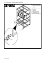
2-3. Selecting A Location And Moving Rack
Ref. 802 203
Y Disconnect input power
conductors from deenergized
supply line BEFORE moving
rack.
1 Lifting Forks
If using lifting forks, be sure forks
are fully inserted.
2 Leveling Foot
Use leveling feet to level rack.
3 Foundation Bracket (4)
Insert anchors into foundation, and
install foundation brackets onto up-
rights, and secure rack.
1
2
3

OM-191 152 Page 7
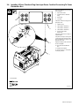
2-4. Installing 3-Phase Twistlock Plug Onto Input Power Cord And Connecting To Power
Distribution Box
Have only qualified persons make
this installation.
1 Input Power Cable
2 Supplied 3-Phase Twistlock
Plug
3 Outer Shell
4 Cord Grip
Slide outer shell and cord grip onto
iput power cord.
5 Twistlock Plug
6 Lead 1 (Brass Terminal X)
7 Lead 2 (Brass Terminal Y)
8 Lead 3 (Brass Terminal Z)
9 Ground Lead (Green
Terminal G)
Strip cord jacket back enough to
separate leads.
Strip leads enough to make good
contact with plug terminals. Make
plug connections and install cord
grip and outer shell.
Tighten assembly screws into shell.
Do not overtighten.
10 Rear Of Power Distribution
Box
11 Twistlock Receptacle
To connect plug to a receptacle,
insert plug, and turn.
802 207-A
Tools Needed:
1
2
10
11
5
6
7
8
9
4
3

OM-191 152 Page 8
2-5. Positioning Jumper Links In Power Source (IHPS II 5 KW Units Only)
Ref. 802 664
Turn Off unit Power switch, and dis-
connect input power.
Jumper links allow operation on dif-
ferent input voltages and are facto-
ry set for the highest input voltage.
Check input voltage available at
site.
Remove wrapper to check jumper
links.
1 Terminal Strip TE2
2 Input Voltage Jumper Link
3 Input Voltage Label
Four jumper links supplied. Look at
jumper links and compare link
position with label.
Move links to match input voltage.
For example, use 230 volts position
on label when 230 volts input power
is available.
Reinstall wrapper.
Tools Needed:
5/16 in
230 460
S-170 603-A
230 460 230230
1
2
3

OM-191 152 Page 9
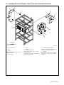
2-6. Installing Disconnect Switch, Power Source And Controller Onto Rack
1 Disconnect Switch
2 Nut
3 T-Bolt
Mount disconnect switch onto rack using
supplied hardware.
4 Power Source
5 Screw
6 Bracket
7 Power Distribution Box
Mount power source onto rack with
supplied hardware.
Eight power sources may be mounted
onto rack cross members.
8 Controller Mounting Bracket
Install and secure mounting bracket to
controller using supplied hardware.
9 Controller
Mount controller onto rack securing top
and bottom of unit using supplied
hardware.
7
2
3
9
4
6
5
1
3/8 in
Tools Needed:
Ref. 802 204-A
2
3
2
8

OM-191 152 Page 10
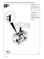
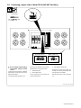
2-7. Connecting To 120 Volts AC Duplex Receptacle
Ref. 802 203
1 120 Volts AC Duplex
Receptacle RC5
This rack supplies up to 15
amperes of 120 volts ac power.
2 Circuit Breaker CB5
The duplex receptacle is protected
from overload by circuit breaker
CB5 (see Section 3-2).
1
2

OM-191 152 Page 11
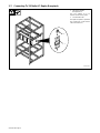
2-8. Positioning Jumper Links In Rack (230 Or 460 VAC Unit Only)
ssb5.1* 2/92 – Ref. 802 208
Y Be sure voltages of input supply to
rack matches voltage of power
sources
Jumper links allow operation on different
input voltages and are factory set for the
highest input voltage.
Check input voltage available at site.
Remove access panel from rear of power
distribution box to check jumper links.
1 Terminal Strip TE1
2 Input Voltage Label
Look at jumper links and compare link
position with unit label.
3 Input Voltage Jumper Links
Move links to match input voltage. For
example, use 230 volts position when 230
volts input power is available.
Reinstall access panel or go on to Section
2-9.
Tools Needed:
3/8 in
1
2
3
230 VOLTS
S-133 010-A
460 VOLTS

OM-191 152 Page 12
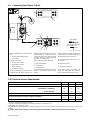
2-9. Connecting Input Power To Rack
Have only qualified persons make this instal-
lation.
1 Rear Of Power Distribution Box
2 Access Panel
Remove access panel.
3 Line Disconnect Switch
4 Strain Relief Connector
5 Input Conductors
6 Grounding Conductor
Select size and length using Section 2-10.
Conductors must be able to carry the com-
bined amperage draw of all power sources
mounted on the rack. Conductor rating must
comply with national, state, and local electri-
cal codes. Use lugs of proper amperage
capacity and correct hole size.
Insert conductors through strain relief.
7 Input Terminal Block
8 Line Terminals
9 Ground Terminal
Connect grounding conductor and input con-
ductors to line terminals and to ground
terminal.
Install and connect grounding conductor and
input conductors in conduit or equivalent to
deenergized line disconnect device.
Be sure grounding conductor goes to an
earth ground.
Reinstall access panel.
10 Overcurrent Protection
Select type and size using Section 2-10.
Install into deenergized line disconnect
device (fused disconnect switch shown).
ssb2.4* 3/93 – Ref. 802 208
Tools Needed:
3/16 in
3/8 in
596
4
8
7
1
2
3
6
10
2-10. Electrical Service Requirements
Input Voltage 230 400 460
Input Amperes At Rated Output 171 83 85
Max Recommended Standard Fuse Or Circuit Breaker Rating In Amperes
Circuit Breaker
1
, Time-Delay
2
200 100 100
Normal Operating
3
250 125 125
Min Input Conductor Size In AWG/Kcmil 2/0 4 3
Max Recommended Input Conductor Length In Feet (Meters)
211
(64)
331
(101)
415
(127)
Min Grounding Conductor Size In AWG/Kcmil 4 6 6
Reference: 1999 National Electrical Code (NEC)
1 Choose a circuit breaker with time-current curves comparable to a Time Delay Fuse.
2 “Time-Delay” fuses are UL class “RK5” .
3 “Normal Operating” (general purpose – no intentional delay) fuses are UL class “K5” (up to and including 60 amp), and UL class “H” ( 65 amp and
above).
Y Caution: Failure to follow these fuse and circuit breaker recommendations could create an electric shock or fire hazard.

OM-191 152 Page 13
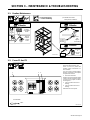
SECTION 3 – MAINTENANCE & TROUBLESHOOTING
3-1. Routine Maintenance
Y Disconnect power
before maintaining.
. Maintain more often
during severe conditions.
3 Months
OR
Blow Out
Or
Vacuum
Inside
Replace
Unreadable
Labels
3 Months
– –
Tape Or
Replace
Cracked
Cable
See
Section
5
Clean
And
Tighten
Connections
6 Months
Power
Source
Manual
– –
Ref. 802 203
3-2. Fuses F1 And F2
Ref. 802 208
Turn Off power sources and
disconnect input power to rack.
Fuses F1 and F2 protect the
auxiliary power transformer T1
from overload.
If F1 or F2 open, remote auxiliary
devices connected to the duplex
receptacle do not work.
1 Rear Of Control Box
Remove rear access panel to left of
center to check and replace fuses
F1 and F2. Use proper tool when
removing fuse.
2 Fuse F1 (See Parts List For
Rating)
3 Fuse F2 (See Parts List For
Rating)
Reinstall rear access panel.
123
3/8 in
Tools Needed:

OM-191 152 Page 14
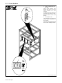
3-3. Circuit Breakers
Ref. 802 203 / Ref. 166 018
1 Power Circuit Breakers CB1
Thru CB8
Power circuit breakers CB1
through CB8 protect the power
source connected to it from
overload.
If a breaker opens, the correspond-
ing power source does not work.
Manually reset the Power circuit
breaker.
2 Circuit Breaker CB5
Circuit breaker CB5 protects the
auxiliary power transformer T1
from overload.
If CB5 opens, the duplex receptacle
does not work. Manually reset CB5.
1
1
2

OM-191 152 Page 15
3-4. Troubleshooting
Trouble Remedy
No output from any power sources; unit completely Place line disconnect switch in On position (see Section 2-8).
inoperative.
Check for open line fuse(s), and replace if needed. Check and reset circuit breakers
(see Section 2-8).
Check for proper input power connections to rack (see Section 2-8).
No output from one power source. Place applicable Power circuit breaker in On position (see Section 3-2).
Check for proper input power connections to power source (see Section 2-8).
Check applicable power source according to its manual.
No 120 volts ac output from duplex receptacle. Reset circuit breaker CB5 (see Section 3-2).
Check fuses F1 and F2, and replace if needed (see Section 3-2).

OM-191 152 Page 16
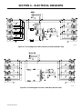
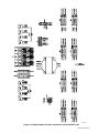
SECTION 4 – ELECTRICAL DIAGRAMS
190 565
Figure 4-1. Circuit Diagram For Rack Control Box (230 Or 460 VAC Unit)
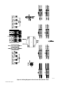
192 728
Figure 4-2. Circuit Diagram For Rack Control Box (400 VAC Unit)
La page charge ...
La page charge ...
La page charge ...
La page charge ...
La page charge ...
La page charge ...
La page charge ...
La page charge ...
-
 1
1
-
 2
2
-
 3
3
-
 4
4
-
 5
5
-
 6
6
-
 7
7
-
 8
8
-
 9
9
-
 10
10
-
 11
11
-
 12
12
-
 13
13
-
 14
14
-
 15
15
-
 16
16
-
 17
17
-
 18
18
-
 19
19
-
 20
20
-
 21
21
-
 22
22
-
 23
23
-
 24
24
-
 25
25
-
 26
26
-
 27
27
-
 28
28


Miller IHPS II RACK Le manuel du propriétaire
- Catégorie
- Système de soudage
- Taper
- Le manuel du propriétaire
- Ce manuel convient également à
dans d''autres langues
- English: Miller IHPS II RACK Owner's manual
Documents connexes
-
Miller KK036825 Le manuel du propriétaire
-
-
-
-
-
-
-
-
-

