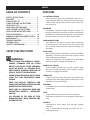
MATCHBIRD™ TRAP
(DOUBLE & SINGLE VERSIONS)
OWNER’S / OPERATOR’S MANUAL
PARTS AND ASSEMBLY INSTRUCTIONS
PART NO. 40904
(SINGLE)
PART NO. 40907
(DOUBLE)
WARNING: THIS MACHINE CAN CAUSE SERIOUS INJURY OR DEATH !
THOROUGHLY READ INSTRUCTIONS AND SAFETY INFORMATION
BEFORE ASSEMBLING, INSTALLING OR OPERATING TRAP !
KEEP THIS INSTRUCTION MANUAL FOR FUTURE REFERENCE.

TABLE OF CONTENTS FEATURES
SAFETY INSTRUCTIONS................................ 2
FEATURES........................................................ 2
STAND PARTS LIST......................................... 3
STAND ASSEMBLY INSTRUCTIONS............. 4
TRAP PARTS LIST............................................ 5
TRAP BODY (BOTTOM VIEW)....................... 6
TRAP ASSEMBLY INSTRUCTIONS................ 7
TRAP OPERATING INSTRUCTIONS.............. 9
TRAP ADJUSTMENTS.................................... 10
MOUNTING TRAP FOR RABBIT TARGETS.. 10
MAINTENANCE.............................................. 10
TROUBLESHOOTING.................................... 11
OPTIONAL TRAP............................................ 11
CONTACT INFORMATION............................ 11
SAFETY INSTRUCTIONS
WARNING:
• IMPACT FROM THE POWERFUL SPRING-
LOADED THROWING ARM OR FLYING
OBJECTS CAN CAUSE SEVERE PERSONAL
INJURY OR DEATH. ALL PERSONS MUST
KEEP CLEAR OF THROWING ARM AND THE
PATH OF TARGETS TO AVOID INJURY.
• OPERATE TRAP FROM REAR ONLY. DO NOT
LEAVE THE TRAP UNATTENDED WHEN
COCKED.
• READ THIS MANUAL CAREFULLY AND
THOROUGHLY BEFORE ASSEMBLING AND
OPERATING THIS TARGET TRAP.
• MAKE SURE ALL OPERATORS READ AND
UNDERSTAND OWNER’S / OPERATOR’S
MANUAL.
• ALL PERSONS IN THE AREA OF TRAP
OPERATION MUST WEAR HEARING AND
EYE PROTECTION.
2
3/4 COCKING FEATURE
• After releasing trigger, arm automatically ends up in a
semi-cocked position. This allows operator to load targets
quickly, safely, and then fully cock arm with a short, easy
pull on the arm.
BALANCED
• Dynamically balanced through computer design. The
force generated by the arm when released is absorbed and
distributed for a smooth throwing action - no “aftershocks”
that make other traps jump and twist out of position.
COMFORTABLE STAND
• Trap stand has four legs to provide stable positioning
on uneven terrain. The trap stand can also be mounted
into a vehicle receiver hitch for additional stability and
portability.
ADJUSTABLE
• Main trap body adjusts vertically for a variety of bird ight
simulations. Trap can also be turned left or right to create
other challenging target ights.
• Tension on mainspring can be adjusted to adapt ight
distance of targets to length of throwing area.
THROWS ALL TARGETS
• Throws standard targets over 70 yards; smaller targets
like minis and midis y farther. Throws singles, “stacked”,
“nested”, and “piggyback” doubles.
TARGET CLIP
• Target clip locates targets consistently on throwing arm
and keeps them from shifting before releasing arm. Fully
adjustable for any type of target.
PORTABLE
• Assembled trap can be easily transported to and from the
practice eld.
SAFE
• Trigger interlock feature provides fail-safe operation.
• Three-piece ring encircles trap to designate throwing arm
path.
DURABLE
• Constructed of heavy gauge steel and high strength
aluminum.
• Paint is electrostatically bonded and baked on for a
durable gloss nish.
ENGLISH

3
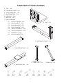
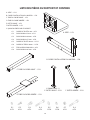
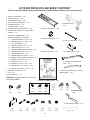
STAND PARTS LIST AND CONTENTS
A. SEAT – 1 EA.
B. TRAP MOUNT FRAME – 1 EA.
C. FRONT FRAME TUBE – 1 EA.
D. REAR FRAME TUBE – 1 EA.
E. FRONT LEGS – 2 EA.
F. REAR LEGS – 2 EA
G. STAND HARDWARE
G-1. 6mm FLAT WASHER – 4 EA.
G-2. M6 x 25mm BOLT – 4 EA.
G-3. M10 x 20mm BOLT – 4 EA.
G-4. M10 x 75mm BOLT – 4 EA.
G-5. 10mm FLAT WASHER – 12 EA.
G-6. 10mm LOCKWASHER – 12 EA.
G-7. M10 HEX NUT – 8 EA.
G-8 M10 x 85mm BOLT 4 EA.
!
A. SEAT – 1 EA.
B. TRAP MOUNT FRAME – 1 EA.
C. FRONT FRAME TUBE – 1 EA.
D. REAR FRAME TUBE – 1 EA.
E.FRONTLEGS–2
EA.
E. FRONT LEGS – 2 EA.
F. REAR LEGS – 2 EA
G-1
4 EA.
G-2
4 EA.
G-3
4 EA.
G-4
4 EA.
G-5
12 EA.
G-6
12 EA.
G-7
8 EA.
G-8
4 EA.

4
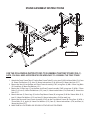
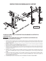
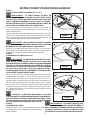
USE THE FOLLOWING INSTRUCTIONS TO ASSEMBLE THE TRAP STAND (FIG-1).
NOTE: YOU WILL NEED APPROPRIATE SIZE WRENCHES TO ASSEMBLE THE TRAP STAND
1. Attach the Front Frame Tube (C) to the Rear Frame Tube (D) using two (2) M10 x85mm Bolts (G-8), four
(4) 10mm Flat Washers (G-5), two (2) 10mm Lockwashers (G-6) and two (2) 10mm Hex Nuts (G-7).
2. Mount the Seat (A) to the Rear and Front Frame Assembly (C&D) using four (4) M6 x 25mm Lag Bolts
(G-2) and four (4) 6mm Flat Washers (G-1).
3. Mount the (2) Rear Legs (F) to the Rear and Front Frame Assembly (C&D) using two (2) M10 x 75mm
Bolts (G-4), two (2) 10mm Flat Washers (G-5), two (2) 10mm Lockwashers (G-6) and two (2) 10mm Hex
Nuts (G-7).
4. Mount the two (2) Front Legs (E) to the Trap Mount Frame (B) using two (2) M10 x 20mm Bolts (G-3),
two (2) 10mm Flat Washers (G-5) and two (2) 10mm Lockwashers (G-6) for each Leg.
5. Mount the Rear and Front Frame Assembly (C&D) to the Trap Mount Frame (B) using four (4) M10 x
75mm Bolts (G-4), eight (8) 10mm Flat Washers (G-5), four (4) 10mm Lockwashers (G-6) and four (4)
10mm Hex Nuts (G-7).
6. MAKE SURE ALL FASTENERS ARE SECURELY ATTACHED AND TIGHTENED.
STAND ASSEMBLY INSTRUCTIONS
FIGURE 1

5
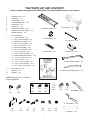
A. THROWING ARM – 1 EA.
B. MAIN BODY – 1 EA.
C. PIVOT MOUNT– 1 EA.
D. FLIGHT CONTROL RAIL – 1 EA.
E. MAINSPRING – 1 EA.
F. TARGET CLIP – 1 EA.
G. FRONT TUBE SUPPORT – 2 EA.
H. ARM PATH INDICATOR TUBING – 3 EA.
I. OWNERS MANUAL – 1 EA.
J. TRAP HARDWARE
J-1. 12mm HEX NUT – 1 EA.
J-2. M12 x 35mm HEX BOLT – 1 EA.
J-3. ROUND HEAD SCREW – 3 EA.
J-4. M10 x 20mm HEX BOLT – 3 EA.
J-5. 10mm FLANGE NUT – 3 EA.
J-6. REAR TUBE SUPPORT – 2 EA.
J-7. M6 x 90mm HEX BOLT – 4 EA.
J-8. 6mm FLANGE NUT – 4 EA.
J-9. M10 x 100mm HEX BOLT – 1 EA.
J-10. NYLON SHOULDER WASHER – 1 EA.
J-11. 10mm FLAT WASHER – 1 EA.
J-12. 10mm HEX NUT – 1 EA.
J-13. 6mm x 12mm LG. BOLT – 2 EA.
J-14. 6mm x 24mm HEX BOLT – 1 EA.
J-15. M6 x 18mm FLAT WASHER – 1 EA.
K. TRAP HANDLE – 1 EA.
L. WRENCH – 1 EA.
M. TRIGGER – 1 EA.
TRAP PARTS LIST AND CONTENTS*
(*parts & contents for single model #40904 shown. Dual model #40907 contains 2 sets of parts.)
A. THROWING ARM – 1 EA.
B. MAIN BODY – 1 EA.
C. PIVOT MOUNT– 1 EA.
D. FLIGHT RAIL – 1 EA.
E. MAINSPRING – 1 EA.
F. TARGET CLIP – 1 EA.
G. FRONT TUBE SUPPORT – 2 EA.
H. ARM PATH INDICATOR TUBING – 3 EA.
J-1
1 EA.
J-2
1 EA.
J-6
2 EA.
J-7
4 EA.
J-8
4 EA.
J-9
1 EA.
J-10
1 EA.
J-11
1 EA.
J-12
1 EA.
I. OWNER’S MANUAL – 1 EA.
J-3
3 EA.
J-4
3 EA.
J-5
3 EA.
THROWING ARM HARDWARE
L. WRENCH – 1 EA.
M. TRIGGER – 1 EA.
J-13
2 EA.
K. TRAP HANDLE – 1 EA.
NOTE: Parts A, B, D, F, J-3, J-4, and J-5
are pre-assembled.
J-14
1 EA.
J-15
1 EA.

6
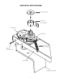
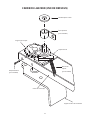
TRAP BODY (BOTTOM VIEW)
12 MM Flat Washer
Swivel Yoke
(Pre-Assembled)
Ratchet Pawl
Ratchet Spring
(Pre-Assembled)
Cotter Pin
(Pre-Assembled)
Ratchet Gear
Trap Body (B)
Throwing Arm Support

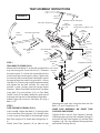
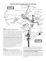
TRAP ASSEMBLY INSTRUCTIONS
STEP 1.
TRAP BODY TO STAND (FIG-2)
Mount the Pivot Mount (C) to the left upright of the
trap stand using the 12mm Hex Nut (J-1). Orientate
the pivot mount (C) so that the serrated face of the
pivot mount faces to the right as shown. Tighten hex
nut securely. After mounting the Pivot Mount, mount
the trap to the pivot mount using the M12 x 35mm
Hex Bolt (J-2). Pivot the trap slightly above horizontal
and tighten the hex bolt securely. This setup will
provide a good starting point for target launch
direction. Attach Trap Body Handle (K) to Trap Body
using bolt (J-14) and washer (J-15) on Trap Body
Handle. Front of Trap Body Handle ts under top of
trap body into slot and is then bolted to Trap Body.
Attach Trigger (M) to tab on Trap Body (B) using 2
Bolts (J-13).
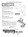
STEP 2.
TUBE SUPPORT ASSEMBLY (FIG-3)
Insert two M6 x 90mm Hex Bolts (J-7) through holes
in the short Rear Tube Support (J-6), through holes
in sides at rear of Trap Body (A) and through second
Rear Tube Support (J-6). Attach 6mm Flange Nuts (J-
8).
Attach Front Tube Supports (G) to front of trap
following the same steps using the same size Hex
Bolts (J-7), and Flange Nuts (J-8).
MAKE SURE WARNINGS ON FRONT TUBE
SUPPORTS ARE UPRIGHT.
Tighten all four nuts on Tube Supports securely.
Slide three pieces of Arm Path Indicator Tubing (H)
over ends of Front Tube Supports (G) and Rear Tube
Supports (J-6). This ring indicates the approximate
path of the Throwing Arm (A).
7
CHAMPION
TRAPS & TARGETS
SKYBIRD
WARNING
AT ALL TIMES! SEIOUS INJURY MAY RESULT.
STAY CLEAR OF THROWING ARM
Trap Body (B)
Trap Body Handle (K)
Tubes
Connect
Front Tube Support (G)
M6 x 90mm Hex
Bolts
(J-7)
M6 x 90mm Hex
Bolts
(J-7)
Tubes
Connect
Arm Path Indicator Tubing (H)
Tubes
Connect
Front Tube Support (G)
6mm
Flange Nuts
(J-8)
Tubes
Connect
Rear Tube
Support (J-6)
6mm
Flange Nuts
(J-8)
Trigger (M) &
6mm x 12mm Lg. Bolts (J-13)
Pivot
Mount (C)
M12 x 35mm
Hex Bolt
(J-2)
FIGURE 3
FIGURE 2
Rear Tube
Support (J-6)
12mm Hex
Nut
(J-1)
6mm x 24mm
Hex Bolt &
M6 x 18mm
Washer
(J-14 & J-15)
Tubes
Connect

8
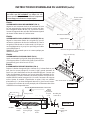
TRAP ASSEMBLY INSTRUCTIONS (continued)
STEP 3.
THROWING ARM ASSEMBLY (FIG-4).
Line-up three holes in Throwing Arm (A) with three
holes in Arm Support. Insert three M10 x 20mm Hex
Bolts (J-4) from bottom through Throwing Arm Support
and Throwing Arm. Add 10mm Flange Nuts (J-5) and
tighten securely.
STEP 4.
FLIGHT CONTROL RAIL ASSEMBLY (FIG-4).
Line-up threaded holes in Flight Control Rail (D) with
top holes in edge of Throwing Arm (A). Attach Control
Rail with three Round Head Screws (J-3). Do not fully
tighten screws until the Target Clip is installed (Step 5)
NOTE: It is normal for these screws to be somewhat
dicult to turn.
STEP 5.
TARGET CLIP ASSEMBLY (FIG-5).
After attaching the Flight Control Rail in the previous
step, slide the Target Clip (F) between the Flight Control
Rail (D) and the Throwing Arm (A) and tighten the three
screws (J-3).
STEP 6.
MAINSPRING ASSEMBLY (FIG-6)
Drop M10 x 100mm Hex Bolt (J-9), threaded end rst, into Mainspring
(E) through largest opening so that threaded end comes out of opposite
tapered end. Make sure Throwing Arm (A) is pointing forward. Connect
hook end of Mainspring (E) through hole in Swivel Yoke. Put threaded
end of Hex Bolt (J-9) through hole in Rear Bracket. Add the Nylon
Shoulder Washer (J-10), 10mm Flat Washer (J-11), and 10mm Hex Nut (J-
12) and nger tighten. Adjustment of Mainspring tension for throwing
targets will be done later.
FIGURE5
TargetClip(F)
ThrowingArm(A)
Round Head Screws
(J-3)
10mm Flange
Nuts (J-5)
Throwing Arm (A)
Flight Control Rail (D)
Arm Support
M10 x 20mm Hex Bolts (J-4)
FIGURE 4
NOTE: Throwing Arm, Flight Control Rail and Target
Clip are PRE-ASSEMBLED. Steps 3-5 provided below
for reference only (assembly by user is not required).
10MMX
125MMHex
Bolt(K4)
Nylon
Shoulder
Washer
(K10)
10MMFlat
Washer(K
5)
10MM
HexNut
(K7)
SwivelYoke
Mainspring
Assembly(E)
CotterPin
Washer
RearBracket
TrapArmFacesForward
FIGURE6
FIGURE 6
Washer
Cotter Pin
Rear Bracket
Trap Arm Faces Forward
10 MM
Hex Nut
(J 12)
Nylon
Shoulder
Washer
(J-10)
10 MM Flat
Washer(J-11)
Swivel Yoke
Mainspring
Assembly (E)

9
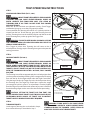
TRAP OPERATING INSTRUCTIONS
STEP 7.
COCKING AND FIRING TRAP (FIG-7, 8 & 9).
WARNING: IMPACT FROM THE POWERFUL SPRING LOADED
THROWING ARM CAN CAUSE SEVERE PERSONAL INJURY OR
DEATH. OPERATE TRAP FROM REAR ONLY. STAY CLEAR OF
THROWING ARM AT ALL TIMES. DO NOT LEAVE TRAP COCKED
AND UNATTENDED.
Make sure all nuts and bolts are tightened securely. Check Trigger
and Ratchet Springs to assure they are properly installed.
Once assembled, the Throwing Arm will be at a 12 o’clock position as
viewed from the rear. To cock the trap, grasp the Throwing Arm and
pull the Throwing Arm into the 6 o’clock position until the tab at the
end of Throwing Arm pushes up against the Trigger Post.
WARNING: FAILURE TO KEEP HANDS AND BODY OUTSIDE
THE THROWING AREA PATH INDICATOR AREA WILL RESULT IN
SERIOUS INJURY OR DEATH.
Press Trigger to release Arm. Throwing Arm will return to the 9
o’clock position. Firmly grasp the Throwing Arm again and repeat the
cocking procedure.
STEP 8.
LOADING TARGETS (FIG 8 & 9).
WARNING: IMPACT FROM THE POWERFUL SPRING LOADED
THROWING ARM CAN CAUSE SEVERE PERSONAL INJURY OR
DEATH. ALWAYS LOAD TARGETS FROM THE LEFT, REAR SIDE OF
TRAP. ARM MUST BE IN THE 9 O’CLOCK POSITION. DO NOT LOAD
TARGETS, ADJUST TARGET CLIP, OR THE FLIGHT CONTROL RAIL
WITH THE THROWING ARM IN THE 6 O’CLOCK, FULLY COCKED
POSITION.
The Throwing Arm will be at approximately the 9 o’clock position after
you have practiced cocking and ring. Place a target on the Throwing
Arm with the lip of the target tucked under the Flight Control Rail.
Slide the target under the Target Clip to the desired position along
the Throwing Arm. The Target Clip should press against the target
just enough to hold it in place. If an adjustment is needed, slightly
bend the Target Clip until the desired amount of pressure is obtained.
Practice loading targets on the arm a few times before proceeding.
CAUTION: SETTING THE TARGET CLIP TOO TIGHT CAN
CAUSE UNPREDICTABLE TARGET FLIGHT WHICH COULD RESULT
IN PERSONAL INJURY. ALWAYS SET TARGET CLIP TO CONTACT
TARGET LIGHTLY. INCREASE PRESSURE IF REQUIRED.
STEP 9.
THROWING TARGETS.
Load target on Throwing Arm as described in Step 8,
then cock and re trap as described in Step 7.
FIGURE 8
Arm at 6 o’clock
position
(Fully cocked)
FIGURE 9
Arm at 9 o’clock
position (Partially
cocked after ring)
12
6
39
FIGURE 7
9
3
6
12
9 3
6
12
12
6
39
WARNING: FLYING OBJECTS CAN CAUSE SEVERE
PERSONAL INJURY OR DEATH. ALWAYS OPERATE WHILE
STANDING BEHIND THE THROWER. NEVER STAND OR
MOVE INTO THE PATH OF A THROWN TARGET.

10
TRAP ADJUSTMENTS
WARNING- IMPACT FROM THE POWERFUL
SPRING LOADED THROWING ARM CAN CAUSE SEVERE
PERSONAL INJURY OR DEATH. MAKE SURE THROWING
ARM IS IN THE 9 O’CLOCK POSITION BEFORE MAKING
ANY ADJUSTMENTS. ALWAYS MAKE ADJUSTMENTS
FROM REAR OF TRAP.
• SETTING MAINSPRING TENSION (FIG-6).
Set Trap Body (B) to a horizontal position. Turn the 10mm
Hex Nut (J-12) on Mainspring (E) counter-clockwise to
decrease spring tension and clockwise to increase spring
tension.
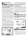
• CHANGING TARGET DIRECTION (FIG-2 & 10).
Minor changes in horizontal direction of ight can be
controlled by placing target at dierent positions under the
Target Clip (F) on the Throwing Arm (A). Place target in the
center position for center (straight ahead), outer position
for right, and inner for left. To make major changes to the
horizontal direction of the target ight, either: 1) Relocate
the entire trap and stand to the desired position or 2)
Loosen 12mm Hex Nut (J-1) on the Pivot Mount (C) where
it mounts to the Trap Stand. The Trap Body (B) can then be
rotated left or right to change the ight of the target left or
right accordingly. Retighten the nut (J-1) after rotating the
trap to the desired position.
• CHANGING FLIGHT ANGLES (FIG. 2).
Changes to the vertical direction of target ight is achieved
by pivoting the Trap Body (B) up or down. To rotate the trap
up or down, loosen the M12 x 35mm Hex Bolt (J-2) on the
Pivot Mount (C) and rotate the trap to the desired elevation
and then retighten the bolt (J-2).
• FLIGHT CONTROL RAIL ADJUSTMENT (FIG-4).
The MatchBird™ Target Trap will throw all styles of targets:
Standard (108 mm), Midi (90mm), Mini (60mm), Rabbit, and
Battue targets. The Flight Control Rail (D) may need to be
moved into the lower set of holes on the Throwing Arm (A)
for targets such as Rabbits and Battues. To do this, remove
FIGURE 10
INNER
CENTER
OUTER
NOTE: Target
Clip not shown
for clarity
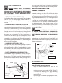
In order to throw Rabbit targets, the trap needs to be
mounted on the right side of the Trap Stand so the rabbit
target can be rolled on its edge along the ground. Although
the existing trap can be removed from the left side of the
Trap Stand and relocated on its side on the right side of
the Trap Stand quickly and easily, it is recommended that
a second trap be purchased and mounted to minimize
changeover time. Two traps will allow the exibility to
mix rabbit and regular targets for the shooter and also
throw what is known as a “Fur and Feather” pair of targets
(One Rabbit target [fur] and a standard target thrown
horizontally [Feather]).
WARNING- MOUNT TRAP ONLY ON RIGHT SIDE
OF SUPPORT. WHEN OPERATING A SIDE MOUNTED
TRAP, STAY CLEAR OF THROWING ARM PATH. MAKE
SURE THROWING ARM CLEARS THE GROUND WHEN
FIRED
Leave at least 6” between ground and bottom of arm
path indicator ring. Place target under Target Clip (F) and
experiment throwing targets. Target Clip (F) must be used
to throw rabbit targets.
MAINTENANCE
The maintenance steps listed below will assure
years of trouble-free performance.
• Keep the Ratchet Mechanisms free from dirt and
debris.
• Each time the trap is used apply OUTERS® TRI-LUBE™
or Gun Oil to the following parts: Trigger Mounting
Rivets, Trigger Springs, Ratchet Pawl Mechanisms, and
Ratchet Springs.
• Inspect Trigger and Ratchet Springs. Replace if bent,
rusted, or broken.
FIGURE 11
NOTE: Target
Clip not shown
for clarity
Inner for
chandelle
targets
Center for
straight
Rabbit
throws
MOUNTING TRAP FOR
RABBIT TARGETS
the three Round Head Screws (J-3) and re-locate Rail. Be
sure to tighten the screws securely after each adjustment.

11
SYMPTOM -
TRIGGER MALFUNCTION
Corrective action:
• Trigger Springs missing or broken - replace
• Tab on end of Throwing Arm missing or damaged -
replace Throwing Arm.
SYMPTOM -
TRIGGER DIFFICULT TO RELEASE
Corrective action:
• Lubricate Trigger Mounting Rivets and Trigger Post,
• Cock trap with less force (or more slowly).
SYMPTOM -
RATCHET MECHANISM MALFUNCTIONS
Corrective action:
• Inspect Ratchet Springs - replace if bent, rusted, or
broken
• Clean and lubricate Ratchet Pawls.
SYMPTOM -
TARGET CLIP RATTLES OR RUBS THROWING ARM
Corrective action:
• Bend target clip with hand.
SYMPTOM -
BROKEN, ERRATIC, OR UNSTABLE TARGETS
Corrective action:
• If rubber strip of Flight Control Rail is damaged, replace
Flight Control Rail Assembly.
• Check position of Flight Control Rail. Use lowest holes for
battues and rabbits - top holes for all other targets.
• Decrease Mainspring Tension.
• Adjust tension of Target Clip. The Target Clip should press
against the target just enough to hold it in place
• Make sure lip of target is tucked under Flight Control Rail.
• If target jars loose before ring, cock trap with less force.
• Inspect targets for ne cracks.
• Bent or cracked Throwing Arm – replace.
• Make sure all screws and bolts are tight on the Throwing
Arm and Flight Control Rail.
SYMPTOM -
“TAILING TARGET” (Target tilts to right or left)
Corrective action:
• Check if trap is placed on a level surface.
SYMPTOM -
FLIGHT DISTANCE GRADUALLY DECREASES
Corrective action:
• Increase Mainspring tension.
• Replace Mainspring Assembly.
CONTACT INFORMATION
Champion Traps and Targets
1 Vista Way
Anoka, MN 55303
Toll Free: (800) 379-1732
Website: www.championtarget.com
Email: tech.expert@vistaoutdoor.com
TRANSPORTATION & STORAGE
WARNING: TRANSPORT AND STORE TRAP
WITH THE MAINSPRING REMOVED AND OUT OF
CHILDREN’S REACH. UNINTENTIONAL FIRING OF
THE TRAP CAN CAUSE SERIOUS INJURY OR DEATH
FROM BEING STRUCK BY THE THROWING ARM.
1. Ensure throwing arm is in the 9 o’clock to 12 o’clock
(uncocked) position.
2. Carefully release spring tension by loosening the
10mm hex nut.
3. Remove the mainspring.
4. Once mainspring is removed, manually rotate
throwing arm to 6 o’clock position.
5. If necessary, detach throwing arm path indicator
and supports.
6. Store trap indoors away from the elements and
out of children’s reach.
WARNING: ALWAYS CHECK THAT THE
THROWING MECHANISM AND SAFETY FEATURES
ARE IN GOOD CONDITION AND THAT THE TRAP
IS FREE OF DEBRIS BEFORE EVERY USE. FAILURE
TO PROPERLY MAINTAIN THIS PRODUCT COULD
INCREASE RISK OF DEATH OR SERIOUS INJURY.
OPTIONAL TRAP
SkyBird™ Trap Assembly...................................40903
Add a second trap to the stand for throwing pairs
of targets and rabbit targets.
Includes foot release base, post mount and all
mounting hardware.
TROUBLESHOOTING

12
WARRANTY CERTIFICATE
Congratulations on the purchase of your new CHAMPION MATCHBIRD™ target thrower. Your new MATCHBIRD™ is warranted to be free from
defects in material or workmanship for a period of six (6) months from the date of purchase. This warranty is extended only to the original consumer
purchaser. Should you believe that your CHAMPION MATCHBIRD™ is defective in material or workmanship, you should contact the CHAMPION
TRAPS & TARGETS Customer Service Department via phone at 800-379-1732. In the event a warranty repair is required, all parts will be provided at no
charge. THIS WARRANTY DOES NOT COVER DEFECTS OR DAMAGE RESULTING FROM: CARELESSNESS, MISUSE, IMPROPER INSTALLATION, MODIFICATION,
OR NORMAL WEAR AND TEAR.
RETAIN THIS WARRANTY CERTIFICATE FOR FUTURE REFERENCE. THE IMPLIED WARRANTIES OF MERCHANTABILITY AND FITNESS FOR A PARTICULAR
PURPOSE ARE LIMITED TO THE DURATION OF THIS LIMITED WARRANTY.
CHAMPION TRAPS AND TARGETS IS NOT LIABLE FOR DAMAGES IN EXCESS OF THE PURCHASE PRICE OF THE PRODUCT AND UNDER NO CIRCUMSTANCES
SHALL CHAMPION TRAPS AND TARGETS BE LIABLE FOR CONSEQUENTIAL OR INCIDENTAL DAMAGES. HOWEVER, SOME STATES DO NOT ALLOW
LIMITATIONS ON INCIDENTAL, OR CONSEQUENTIAL DAMAGES, SO THE ABOVE LIMITATION OR EXCLUSION MAY NOT APPLY TO YOU.
The above warranty provides the sole and exclusive warranty available to the customer in the event of a defect in material or workmanship in the CHAMPION MATCHBIRD™ .
This warranty gives you speci c legal rights, and you may also have other rights which vary from State to State.
CHAMPION TRAPS AND TARGETS
1 VISTA WAY
ANOKA, MN 55303
1-800-379-1732
www.championtarget.com

TABLE DES MATIÈRES CARACTÉRISTIQUES
CONSIGNES DE SÉCURITÉ ....................................... 13
CARACTÉRISTIQUES ................................................. 13
LISTE DES PIÈCES DU SUPPORT ............................. 14
INSTRUCTIONS D'ASSEMBLAGE DU SUPPORT .... 15
LISTE DES PIÈCES DU LANCEUR ............................. 16
CADRE DU LANCEUR (VUE DE DESSOUS) ............ 17
INSTRUCTIONS D'ASSEMBLAGE DU LANCEUR .... 18
INSTRUCTIONS D'UTILISATION DU LANCEUR ..... 20
RÉGLAGES DU LANCEUR ......................................... 21
ASSEMBLER LE LANCEUR POUR LES
CIBLES LAPINS ........................................................... 21
ENTRETIEN ................................................................. 21
DÉPANNAGE .............................................................. 22
LANCEUR FACULTATIF .............................................. 22
COORDONNÉES ......................................................... 22
CONSIGNES DE SÉCURITÉ
AVERTISSEMENT:
• LA FORCE D'IMPACT DU BRAS DE LANCE-
MENT ACTIVÉ PAR RESSORT ET LA PROJEC-
TION DE DÉBRIS PEUVENT CAUSER DES BLES-
SURES GRAVES OU MÊME LA MORT. TOUTES
LES PERSONNES PRÉSENTES DOIVENT REST-
ER À L'ÉCART DU BRAS DE LANCEMENT ET DE
LA TRAJECTOIRE DES CIBLES AFIN D'ÉVITER
TOUTE BLESSURE.
• FAIRE FONCTIONNER LE LANCEUR UNIQUE-
MENT EN SE PLAÇANT À L'ARRIÈRE. NE PAS
LAISSER LE LANCEUR SANS SURVEILLANCE
LORSQU'IL EST EN MODE ARMÉ («COCKED»).
• LIRE CE MANUEL ATTENTIVEMENT ET EN-
TIÈREMENT AVANT D'ASSEMBLER ET DE FAIRE
FONCTIONNER CE LANCEUR.
• S'ASSURER QUE TOUS LES UTILISATEURS LIS-
ENT ET COMPRENNENT LE MANUEL DU PRO-
PRIÉTAIRE/UTILISATEUR.
• TOUTES LES PERSONNES PRÉSENTES DANS
LA ZONE DE FONCTIONNEMENT DU LANCEUR
DOIVENT PORTER DES DISPOSITIFS DE PRO-
TECTION OCULAIRE ET AUDITIVE.
13
CARACTÉRISTIQUE D'ARMEMENT AU 3/4
• Après l'activation du déclencheur, le bras retourne au-
tomatiquement en position semi-armée. Cela permet
à l'utilisateur de charger les cibles rapidement et de façon
sécuritaire, puis d'armer complètement le bras d'une traction
simple et courte.
ÉQUILIBRÉ
• Conception équilibrée dynamiquement par ordinateur.
La force générée par le déclenchement du bras est absorbée
et distribuée pour procurer un tir uide – sans les contre-
coups qui font sauter et se déplacer d'autres lanceurs.
SUPPORT CONFORTABLE
• Le support de lanceur comprend quatre pattes capables
de fournir un positionnement stable sur un terrain inégal.
Le support peut également être attelé à un réceptacle pour
remorque pour une stabilité et une portabilité additionnelle.
RÉGLABLE
• Le cadre principal s'ajuste verticalement pour simuler le vol
d'oiseaux variés. Le lanceur peut également être tourné vers
la droite ou vers la gauche pour créer d'autres dés de tir au
vol.
• La tension du ressort principal peut être ajustée pour adapt-
er la distance de vol des cibles à la longueur de la zone de
lancement.
LANCE TOUTES LES CIBLES
• Capable de lancer les cibles standards sur 70verges; les plus
petites cibles comme les minis et les midis volent plus loin.
Permet de lancer des cibles simples ou des cibles doubles su-
perposées, imbriquées ou combinées.
CLIP POUR CIBLES
• Le clip pour cibles place les cibles de manière constante sur le
bras de lancement et les empêche de se déplacer avant le dé-
clenchement. S'ajuste entièrement pour tout type de cible.
PORTATIF
• Le lanceur assemblé se transporte facilement jusqu'à la zone
d'entraînement et vice-versa.
SÛR
• Le dispositif de déclenchement ore un fonctionnement
sans faille.
• Un cerceau en trois morceaux entoure le lanceur pour in-
diquer la trajectoire du bras de lancement.
DURABLE
• Fabriqué en acier de haut calibre et en aluminium de haute
résistance.
• La peinture est xée par procédé électrostatique et cuite
pour produire un ni brillant et durable.
FRANÇAIS

14
LISTE DES PIÈCES DU SUPPORT ET CONTENU
A. SIÈGE – 1 CH.
B. CADRE D'INSTALLATION DU LANCEUR – 1CH.
C. TUBE DU CADRE AVANT – 1CH.
D. TUBE DU CADRE ARRIÈRE – 1CH.
E. PATTES AVANT – 2CH.
F. PATTES ARRIÈRE – 2CH
G. QUINCAILLERIE POUR LE SUPPORT
G-1. RONDELLE PLATE 6mm – 4CH.
G-2. BOULON M6 x 25mm – 4CH.
G-3. BOULON M10 x 20mm – 4CH.
G-4. BOULON M10 x 75mm – 4CH.
G-5. RONDELLE PLATE 10mm – 12CH.
G-6. RONDELLE FREIN 10mm – 12CH.
G-7. ÉCROU HEXAGONAL M10 – 8CH.
G-8 BOULON M10 x 85mm – 4CH.
!
A. SIÈGE – 1 CH.
B. CADRE D'INSTALLATION DU LANCEUR – 1CH.
C. TUBE DU CADRE AVANT – 1CH.
D. TUBE DU CADRE ARRIÈRE – 1CH.
E.FRONTLEGS–2
EA.
E. PATTES AVANT – 2CH.
F. PATTES ARRIÈRE – 2CH
G-1
4CH.
G-2
4CH.
G-3
4CH.
G-4
4CH.
G-5
12CH.
G-6
12CH.
G-7
8CH.
G-8
4CH.

15
SUIVRE LES DIRECTIVES SUIVANTES POUR ASSEMBLER LE SUPPORT DU
LANCEUR (FIG.1).
REMARQUE: VOUS AUREZ BESOIN DE CLÉS DE DIMENSION APPROPRIÉE POUR
ASSEMBLER LE SUPPORT DU LANCEUR
1. Attacher le tube du cadre avant (C) au tube du cadre arrière (D) en utilisant deux (2) boulons M10 x 85mm
(G-8), quatre (4) rondelles plates 10mm (G-5), deux (2) rondelles freins 10mm (G-6) et deux (2) écrous hex-
agonaux 10mm (G-7).
2. Installer le siège (A) à l'assemblage arrière et avant du cadre (C et D) à l'aide de quatre (4) tire-fonds
M6 x 25mm (G-2) et quatre (4) rondelles plates 6mm (G-1).
3. Attacher les deux (2) pattes arrière (F) au cadres avant et arrière(C et D) en utilisant deux (2) boulons M10 x
75mm (G-4), deux (2) rondelles plates 10mm (G-5), deux (2) rondelles freins 10mm (G-6) et deux (2) écrous
hexagonaux 10mm (G-7).
4. Attacher les deux (2) pattes avant (E) au cadre du lanceur (B) en utilisant deux (2) boulons M10 x 20mm
(G-3), deux (2) rondelles plates 10mm (G-5) et deux (2) rondelles freins 10mm (G-6) pour chacune des
pattes.
5. Installer les cadres avant et arrière (C et D) au cadre du lanceur (B) en utilisant quatre (4) boulons M10 x
75mm (G-4), huit (8) rondelles plates 10mm (G-5), quatre (4) rondelles freins 10mm (G-6) et quatre (4)
écrous hexagonaux 10mm (G-7).
6. S'ASSURER QUE TOUTES LES FIXATIONS SONT SOLIDEMENT ATTACHÉES ET BIEN SERRÉES.
INSTRUCTIONS D'ASSEMBLAGE DU SUPPORT
FIGURE 1

16
A. BRAS DE LANCEMENT – 1CH.
B. CADRE PRINCIPAL – 1CH.
C. FIXATION POUR PIVOT – 1CH.
D. RAIL-GUIDE DE LANCEMENT – 1CH.
E. RESSORT PRINCIPAL – 1CH.
F. CLIP POUR CIBLES – 1CH.
G. SUPPORT AVANT POUR CERCEAU – 2CH.
H. CERCEAU INDICATEUR DE LA TRAJECTOIRE
DUBRAS – 3CH.
I. MANUEL DU PROPRIÉTAIRE – 1CH.
J. QUINCAILLERIE POUR LE LANCEUR
J-1. ÉCROU HEXAGONAL 12mm – 1CH.
J-2. BOULON HEX M12 x 35mm – 1CH.
J-3. VIS À TÊTE RONDE – 3CH.
J-4. BOULON HEX M10 x 20mm – 3CH.
J-5. ÉCROU À BRIDE 10mm – 3CH.
J-6. SUPPORT ARRIÈRE POUR CERCEAU – 2CH.
J-7. BOULON HEX M6 x 90mm – 4CH.
J-8. ÉCROU À BRIDE 6mm – 4CH.
J-9. BOULON HEX M10 x 100mm – 1CH.
J-10. RONDELLE D'ÉPAULEMENT EN NYLON – 1CH.
J-11. RONDELLE PLATE 10mm – 1CH.
J-12. ÉCROU HEX 10mm – 1CH.
J-13. BOULON LG 6mm x 12mm – 2CH.
J-14. BOULON HEX 6mm x 24mm – 1CH.
J-15. RONDELLE PLATE M6 x 18mm – 1CH.
K. POIGNÉE DU LANCEUR – 1CH.
L. CLÉ – 1CH.
M. DÉCLENCHEUR – 1CH.
LISTE DES PIÈCES DU LANCEUR ET CONTENU*
(*pièces et contenu du modèle simple no 40904 montrés. Le modèle double no 40907 contient 2 jeux de pièces.)
A. BRAS DE LANCEMENT – 1CH.
B. CADRE PRINCIPAL
– 1CH.
C. FIXATION POUR PIVOT – 1CH.
D. RAIL DE LANCEMENT – 1CH.
E. RESSORT PRINCIPAL – 1CH.
F. CLIP POUR CIBLES – 1CH.
G. SUPPORT AVANT POUR CER-
CEAU – 2CH.
H. CERCEAU INDICATEUR DE LA TRAJEC-
TOIRE DU BRAS – 3CH.
J-1
1CH.
J-2
1CH.
J-6
2CH.
J-7
4CH.
J-8
4CH.
J-9
1CH.
J-10
1CH.
J-11
1CH.
J-12
1CH.
I. MANUEL DU PROPRIÉTAIRE – 1CH.
J-3
3CH.
J-4
3CH.
J-5
3CH.
QUINCAILLERIE DU BRAS DE LANCEMENT
L. CLÉ – 1CH.
M. DÉCLENCHEUR
– 1CH.
J-13
2CH.
K. POIGNÉE DU LANCEUR – 1CH.
REMARQUE: Les pièces A, B, D, F, J-3, J-4 et J-5
sont pré-assemblées.
J-14
1CH.
J-15
1CH.

17
CADRE DU LANCEUR (VUE DE DESSOUS)
Rondelle plate 12mm
Étrier pivotant
(pré-assemblé)
Cliquet d'arrêt
Ressort du
cliquet
(pré-assemblé)
Goupille fendue
(pré-assemblé)
Engrenage à cliquet
Cadre du lanceur (B)
Support du bras de lancement

INSTRUCTIONS D'ASSEMBLAGE DU LANCEUR
ÉTAPE1.
CADRE DU LANCEUR SUR SUPPORT (FIG.2)
Assembler la xation du pivot (C) au côté supérieur
gauche du support en utilisant le boulon hexagonal
12mm (J-1). Orienter la xation du pivot (C) de façon àce
que sa surface dentelée soit dirigée vers la droite, tel qu'il-
lustré. Bien serrer l'écrou hexagonal. Après avoir assemblé
la xation du pivot, relier le lanceur à la xation en util-
isant le grand boulon hexagonal M12 x 35mm (J-2). Faire
pivoter légèrement le lanceur sur l'axe horizontal et serrer
solidement le boulon hexagonal. Cette installation fourni-
ra un bon point de départ pour la direction du lancement
de cibles.Fixer la poignée (K) au cadre du lanceur à l'aide
du boulon (J-14) et de la rondelle (J-15) sur la poignée du
cadre du lanceur. Le devant de la poignée du cadre s'in-
stalle dans la fente située sous le dessus du cadre et est
ensuite boulonné au cadre du lanceur.
Attacher le déclencheur (M) à l'onglet du cadre du lanceur
(B) à l'aide de 2 boulons (J-13).
ÉTAPE2.
ASSEMBLAGE DU SUPPORT DE CERCEAU (FIG.3)
Insérer deux gros boulons hex M6 x 90 mm (J-7)
à travers les trous du support de cerceau arrière
court (J-6), les trous de côtés à l'arrière du cadre
du lanceur (A) et le second support de cerceau ar-
rière (J-6). Attacher les écrous à bride 6 mm (J-8).
Attacher les supports de cerceau (G) à l'avant du lanceur en
suivant les mêmes étapes et en utilisant la même taille de
boulons à tête hexagonale (J-7) et les écrous à bride (J-8).
S'ASSURER QUE LES AVERTISSEMENTS FIGURANT SUR
LES SUPPORTS AVANT SONT À L'ENDROIT.
Bien serrer les quatre écrous du support de cerceau. Gliss-
er les trois morceaux du cerceau indicateur de trajec-
toire du bras (H) sur les supports avant (G) et arrière (J-6).
Ce cerceau indique la trajectoire approximative du bras de
lancement (A).
18
CHAMPION
TRAPS & TARGETS
SKYBIRD
WARNING
AT ALL TIMES! SEIOUS INJURY MAY RESULT.
STAY CLEAR OF THROWING ARM
Cadre du
lanceur (B)
Poignée du cadre du lanceur (K)
Support avant pour cerceau (G)
Boulons hexagonaux
M6 x 90mm
(J-7)
Boulons hexagonaux
M6 x 90mm
(J-7)
Raccordement du cerceau
Cerceau indicateur de la trajectoire du bras (H)
Raccordement du
cerceau
Support avant pour cerceau (G)
6mm
Écrous à bride
(J-8)
Raccordement
du cerceau
Support arrière pour
cerceau (J-6)
Écrous à
bride 6mm
(J-8)
Déclencheur (M) et gros
boulons 6mm x 12mm (J-13)
Fixation pour pivot
(C)
Boulons
hexagonaux
M12 x 35mm
(J-2)
FIGURE3
FIGURE2
Support arrière pour
cerceau (J-6)
Écrou hexagonal
12mm (J-1)
Boulon hex 6mm
x 24mm et ron-
delle M6 x 18mm
(J-14 et J-15)
Raccordement
du cerceau

19
INSTRUCTIONS D'ASSEMBLAGE DU LANCEUR (suite)
ÉTAPE3.
ASSEMBLAGE DU BRAS DE LANCEMENT (FIG.4).
Aligner les trois ouvertures du bras de lancement (A) avec
les trois ouvertures du support du bras. Insérer trois bou-
lons hexagonaux M10 x 20mm (J-4), à partir du dessous,
à travers le support du bras et le bras de lancement. Ajouter
des écrous à bride 10mm (J-5) et bien serrer.
ÉTAPE4.
ASSEMBLAGE DU RAIL-GUIDE DE LANCEMENT(FIG.4).
Aligner les ouvertures letées du rail-guide (D) avec les
ouvertures supérieures du bras de lancement (A). Fixer le
rail-guide à l'aide de trois vis à tête ronde (J-3). Ne pas ser-
rer complètement les vis jusqu'à ce que le clip pour cibles
soit installé (Étape5)
REMARQUE: Il est normal que ces vis soient quelque peu
diciles à tourner.
ÉTAPE5.
ASSEMBLAGE DU CLIP POUR CIBLES (FIG.5).
Après avoir attaché le rail-guide (étape précédente), gliss-
er le clip pour cibles (F) entre le rail-guide (D) et le bras de
lancement (A), puis serrer les trois vis (J-3).
FIGURE5
TargetClip(F)
ThrowingArm(A)
Vis à tête ronde
(J-3)
Écrous à bride
10mm (J-5)
Bras de lancement (A)
Rail-guide de
lancement (D)
Support du bras
Boulons hexagonaux M10 x 20mm (J-4)
FIGURE 4
REMARQUE: Le bras de lancement, le rail-guide et le clip
pour cibles sont PRÉ-ASSEMBLÉS. Les étapes 3 à 5 ci-
dessous sont fournies à des ns de référence uniquement
(l'assemblage par l'utilisateur n'est pas requis).
10MMX
125MMHex
Bolt(K4)
Nylon
Shoulder
Washer
(K10)
10MMFlat
Washer(K
5)
10MM
HexNut
(K7)
SwivelYoke
Mainspring
Assembly(E)
CotterPin
Washer
RearBracket
TrapArmFacesForward
FIGURE6
FIGURE 6
Rondelle
Goupille
fendue
Support
arrière
Le bras de lancement fait face vers l'avant
10mm
Écrou hexagonal
(K-7)
Rondelle
d'épaulement
en nylon
(J-10)
Rondelle plate
10mm (K-5)
Étrier pivotant
Assemblage du
ressort principal
(E)
ÉTAPE6.
ASSEMBLAGE DU RESSORT PRINCIPAL (FIG.6)
Déposer le boulon hexagonal M10 x 100mm (J-9), le bout leté en pre-
mier, dans le ressort principal (E) à travers la plus grande ouverture de
façon àce que le bout leté ressorte du côté elé opposé. S'assurer que
le bras de lancement (A) pointe vers l'avant. Accrocher l'extrémité du res-
sort principal (E) à travers l'ouverture de l'étrier pivotant. Faire passer l'ex-
trémité leté du boulon hexagonal (J-9) à travers l'ouverture du support
arrière. Ajouter la rondelle à épaulement en nylon (J-10), une rondelle
plate 10 mm (J-11), un écrou hexagonal 10mm (J-12), puis serrer à la main.
Le réglage de la tension du ressort principal pour le lancement des cibles
s'eectuera à une étape ultérieure.
Clip pour cibles (F)
Bras de lancement (A)

20
INSTRUCTIONS D'UTILISATION DU LANCEUR
ÉTAPE7.
ARMER ET DÉCLENCHER LE LANCEUR (FIG.7, 8 et 9).
AVERTISSEMENT : LA FORCE D'IMPACT DU BRAS DE
LANCEMENT ACTIVÉ PAR LE RESSORT PUISSANT PEUT CAUSER
DES BLESSURES GRAVES OU MÊME LA MORT. FAIRE FONCTION-
NER LE LANCEUR UNIQUEMENT EN SE PLAÇANT À L'ARRIÈRE.
RESTER À L'ÉCART DU BRAS DE LANCEMENT EN TOUT TEMPS. NE
PAS LAISSER LE LANCEUR ARMÉ SANS SURVEILLANCE.
S'assurer que tous les écrous et boulons sont bien serrés. Vérier les
ressorts du déclencheur et du cliquet pour s'assurer qu'ils sont in-
stallés adéquatement.
Une fois assemblé, le bras de lancement sera en position 12h vu de
l'arrière. Pour armer le lanceur, saisir le bras de lancement et le tirer
vers la position 6h jusqu'à ce que l'onglet à l'extrémité du bras de
lancement soit appuyé contre la tige du déclencheur.
AVERTISSEMENT: NE PAS GARDER LES MAINS ET LE CORPS
HORS DE LA ZONE DE LANCEMENT INDIQUÉE PAR LE CERCEAU
ENTRAÎNERA DES BLESSURES GRAVES, VOIRE LA MORT.
Appuyer sur le déclencheur pour relâcher le bras. Le bras de lance-
ment retournera à la position 9 heures. Saisir fermement le bras de
lancement à nouveau et répéter la procédure d'armement.
ÉTAPE8.
CHARGEMENT DES CIBLES (FIG.8 et 9).
AVERTISSEMENT: LA FORCE D'IMPACT DU BRAS DE LANCE-
MENT ACTIVÉ PAR LE RESSORT PUISSANT PEUT CAUSER DES
BLESSURES GRAVES OU MÊME LA MORT. TOUJOURS RECHARGER
LES CIBLES À PARTIR DU CÔTÉ GAUCHE ARRIÈRE DU LANCEUR.
LE BRAS DOIT SE TROUVER EN POSITION 9H. NE PAS CHARGER
DE CIBLES, NE PAS AJUSTER LE CLIP POUR CIBLES OU LE RAIL-
GUIDE LORSQUE LE BRAS DE LANCEMENT SE TROUVE EN POSI-
TION 6HEURES (COMPLÈTEMENT ARMÉ).
Après vous être entrainé à armer et déclencher le lanceur, le bras de
lancement sera en position 9h. Placer une cible sur le bras de lance-
ment, le rebord de la cible sous le rail-guide. Glisser la cible sous le
clip pour cibles à la position désirée, le long du bras de lancement. Le
clip pour cibles devrait appuyer sur la cible juste assez pour la main-
tenir en place. Si un ajustement s'avère nécessaire, plier doucement
le clip pour cibles pour obtenir le degré de pression souhaité. S'exer-
cer à charger des cibles sur le bras de lancement àquelques reprises
avant d'utiliser le lanceur.
ATTENTION : UN RÉGLAGE TROP SERRÉ DU CLIP POUR
CIBLES RISQUERAIT DE PROVOQUER UNE TRAJECTOIRE IMPRÉVIS-
IBLE DE LA CIBLE ET POURRAIT CAUSER DES BLESSURES. TOUJO-
URS RÉGLER LE CLIP DE FAÇON À CE QU'IL TOUCHE LÉGÈREMENT
LA CIBLE. AUGMENTER LA PRESSION SI NÉCESSAIRE.
ÉTAPE9.
LANCEMENT DES CIBLES.
Charger la cible su le bras de lancement tel que décrit
à l'Étape8, puis armer et déclencher le lanceur tel que
décrit à l'Étape7.
FIGURE8
Armer en position 6h
(Complètement armé)
FIGURE9
Armer en position 9h
(partiellement armé après
avoir été déclenché)
12
6
39
FIGURE7
9
3
6
12
9 3
6
12
12
6
39
AVERTISSEMENT : LES OBJETS PROJETÉS PEU-
VENT CAUSER DES BLESSURES GRAVES OU MÊME LA
MORT. TOUJOURS FAIRE FONCTIONNER LE LANCEUR EN
SE TENANT DERRIÈRE. NE JAMAIS SE TENIR OU SE DÉ-
PLACER DANS LA TRAJECTOIRE D'UNE CIBLE LANCÉE.
La page est en cours de chargement...
La page est en cours de chargement...
La page est en cours de chargement...
La page est en cours de chargement...
-
 1
1
-
 2
2
-
 3
3
-
 4
4
-
 5
5
-
 6
6
-
 7
7
-
 8
8
-
 9
9
-
 10
10
-
 11
11
-
 12
12
-
 13
13
-
 14
14
-
 15
15
-
 16
16
-
 17
17
-
 18
18
-
 19
19
-
 20
20
-
 21
21
-
 22
22
-
 23
23
-
 24
24


Champion 40907 Owner's And Operator's Manual
- Taper
- Owner's And Operator's Manual
- Ce manuel convient également à
dans d''autres langues
- English: Champion 40907