CAME AGT KT A, AGT KT V Guide d'installation
- Taper
- Guide d'installation

CAME S.p.A.
Via Martiri Della Libertà, 15
31030 - Dosson di Casier
Treviso - Italy
AGT KT A - AGT KT V
12 3
AGT KT A
PEC
45 6
7
8
9
AGT KT A
AGT A
AGT KT A
AGATA C
AGT A
PEC
AGATA C
AGT KT A
4
3
2
1
5
6
7
8
AGT KT V
AGT V
PEV
AGT KT V
AGATA VC
AGT KT V
OPALE
AGT KT V
AGT KT V
4
3
2
1
5
6
7
8
AGT V
AGT KT V
OPALE
PEV
AGATA VC
FA01439M4A
IT
Italiano
EN
English
FR
Français
RU
Pусский
Istruzioni originali
FA01439M4A - 12/2019
ITALIANO
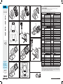
Istruzioni per l'intallazione
Fissare la base o la staa di fissaggio del derivato al supporto da tavolo, utilizzando le viti in dotazione.
Far passare il cavo in dotazione attraverso l'apposito foro posteriore.
Eseguire il cablaggio seguendo le indicazioni delle tabelle.
Chiudere la scanalatura passacavo posteriore fissando la piastrina con le viti in dotazione.
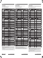
DERIVATI INTERNI CITOFONICI – Collegamenti al Sistema X1
N. Pin
Spina RJ45 Morsetto Morsettiera del derivato interno
Colore conduttori del cavo di collega-
mento in dotazione Funzione morsetti del derivato interno
[1] Bianco-Arancio [B] Linea
[2] Arancio [B] Linea
[3] Bianco-Verde Libero
[4] Blu
+
Chiamata dal pianerottolo
[5] Bianco-Blu
–
Chiamata dal pianerottolo
[6] Verde Libero
[7] Bianco-Marrone [AL] Ingresso Allarme
[8] Marrone Libero
DERIVATI INTERNI CITOFONICI – Collegamenti al Sistema 200
N. Pin Spina RJ45 Morsetto Morsettiera del derivato interno
Colore conduttori del cavo di collega-
mento in dotazione Funzione morsetti del derivato interno
[1] Bianco-Arancio Libero per funzioni aggiuntive
[2] Arancio Libero per funzioni aggiuntive
[3] Bianco-Verde [5] Comune (massa)
[4] Blu [8] Audio al derivato
[5] Bianco-Blu [9] Audio dal derivato
[6] Verde Libero per funzioni aggiuntive
[7] Bianco-Marrone [7] Chiamata
[8] Marrone Libero per funzioni aggiuntive
DERIVATI INTERNI VIDEOCITOFONICI – Collegamenti al Sistema X1
N. Pin
Spina RJ45 Morsetto Morsettiera del derivato interno
Colore conduttori del cavo di collega-
mento in dotazione Funzione morsetti del derivato interno
[1] Bianco-Arancio [B] Linea
[2] Arancio [B] Linea
[3] Bianco-Verde [+] Alimentazione/Libero dove non prev.
[4] Blu
+
Chiamata dal pianerottolo
[5] Bianco-Blu
–
Chiamata dal pianerottolo
[6] Verde [-] Alimentazione/Libero dove non prev.
[7] Bianco-Marrone [AL] Ingresso Allarme
[8] Marrone Libero
DERIVATI INTERNI VIDEOCITOFONICI – Collegamenti al Sistema 200
N. Pin
Spina RJ45
Morsetto
Morsettiera del derivato interno
Colore conduttori del cavo di collega-
mento in dotazione Funzione morsetti del derivato interno
[1] Bianco-Arancio [3] Video positivo
[2] Arancio [4] Video negativo
[3] Bianco-Verde [5] Comune (massa)
[4] Blu [8] Audio al derivato
[5] Bianco-Blu [9] Audio al derivato
[6] Verde [6] +Alimentazione
[7] Bianco-Marrone [7] Chiamata
[8] Marrone [20] Ingresso chiamata dal pianerottolo
SMALTIMENTO - Assicurarsi che il materiale d’imballaggio non venga disperso nell’ambiente, ma smaltito se-
guendo le norme vigenti nel paese di utilizzo del prodotto. Alla fine del ciclo di vita dell’apparecchio evitare che
lo stesso venga disperso nell’ambiente.Lo smaltimento dell’apparecchiatura deve essere eettuato rispettando le
norme vigenti e privilegiando il riciclaggio delle sue parti costituenti. Sui componenti, per cui è previsto lo smalti-
mento con riciclaggio, sono riportati il simbolo e la sigla del materiale.

FA01439M4A - 12/2019
Translation of the original instructions Traduction des instructions originales Перевод оригинальных инструкций
РУССКИЙ
Руководство по установке
Закрепите с помощью прилагаемых винтов основание или кронштейн крепления абонентского устройства к
суппорту для настольной установки. Пропустите кабель подключения в соответствующее отверстие сзади.
Следуя инструкциям, приведенным в таблицах, подключите кабель.
Закрепите кабель, прикрутив ческую пластину к суппорту.
АБОНЕНТСКИЕ УСТРОЙСТВА АУДИО - Подключение к Системе Х1
№ Контакта
Разъем RJ45 Клемма Клеммы абонентского устройства
Цвет оплетки прилагаемых соеди-
нительных проводов Функция клемм абонентского устрой-
ства
[1] Бело-Оранжевый [B] Вход линии шины
[2] Оранжевый [B] Вход линии шины
[3] Бело-Зеленый Свободный
[4] Синий
+
Дверной звонок
[5] Бело-Синий
–
Дверной звонок
[6] Зеленый Свободный
[7] Бело-Коричневый [AL] Вход сигнала тревоги
[8] Коричневый Свободный
АБОНЕНТСКИЕ УСТРОЙСТВА АУДИО - Подключение к Системе 200
№ Контакта Разъем RJ45 Клемма Клеммы абонентского устройства
Цвет оплетки прилагаемых соеди-
нительных проводов Функция клемм абонентского устрой-
ства
[1] Бело-Оранжевый Свободный (для дополнительных функ-
ций)
[2] Оранжевый Свободный (для дополнительных функ-
ций)
[3] Бело-Зеленый [5] Общий (масса)
[4] Синий [8] Аудио к абонентскому устройству
[5] Бело-Синий [9] Аудио от абонентского устройства
[6] Зеленый Свободный (для дополнительных функ-
ций)
[7] Бело-Коричневый [7] Вызов
[8] Коричневый Свободный (для дополнительных функ-
ций)
АБОНЕНТСКИЕ УСТРОЙСТВА ВИДЕО - Подключение к Системе Х1
№ Контакта
Разъем RJ45 Клемма Клеммы абонентского устройства
Цвет оплетки прилагаемых соеди-
нительных проводов Функция клемм абонентского устрой-
ства
[1] Бело-Оранжевый [B] Вход линии шины
[2] Оранжевый [B] Вход линии шины
[3] Бело-Зеленый [+] Питание/свободно, если не предусм
[4] Синий
+
Дверной звонок
[5] Бело-Синий
–
Дверной звонок
[6] Зеленый [-] Питание/свободно, если не предусм
[7] Бело-Коричневый [AL] Вход сигнала тревоги
[8] Коричневый Свободный
АБОНЕНТСКИЕ УСТРОЙСТВА ВИДЕО - Подключение к Системе 200
№ Контакта
Разъем RJ45
Клемма
Клеммы абонентского устройства
Цвет оплетки прилагаемых соеди-
нительных проводов Функция клемм абонентского устрой-
ства
[1] Бело-Оранжевый [3] Плюс видеосигнала
[2] Оранжевый [4] Минус видеосигнала
[3] Бело-Зеленый [5] Общий (масса)
[4] Синий [8] Аудио к абонентскому устройству
[5] Бело-Синий [9] Аудио от абонентского устройства
[6] Зеленый [6] + Питание
[7] Бело-Коричневый [7] Вызов
[8] Коричневый [20] Вход дверного звонка
УТИЛИЗАЦИЯ - Не загрязняйте окружающую среду упаковочным материалом: убедитесь, что утилизация
выполнена в соответствии с нормативами, действующими в стране использования продукта. По окончании
срока службы оборудования утилизируйте его надлежащим образом.
Оборудование следует утилизировать в соответствии с действующи- ми нормативами, по возможности
используя повторную переработку составных частей.
Компоненты, подлежащие повторной переработке, имеют соответствующий символ и аббревиатуру ма-
териала.
ENGLISH
Installation Instructions
Fasten the base or mounting bracket of the receiver to the table-top mounting, using the screws provided.
Thread the cable provided through the dedicated hole at the rear.
Carry out the cabling following the instructions in the tables.
Close the rear cable gland slot by attaching the plate with the screws provided.
AUDIO ENTRY SYSTEM INTERNAL RECEIVERS - Connections to System X1
Pin no.
RJ45 connector Terminal Internal receiver terminal block
Colour of wires in connecting cable
supplied Function of internal receiver's terminals
[1] White-Orange [B] Line
[2] Orange [B] Line
[3] White-Green Free
[4] Blue
+
Doorbell
[5] White-Blue
–
Doorbell
[6] Green Free
[7] White-Brown [AL] Alarm Input
[8] Brown Free
AUDIO ENTRY SYSTEM INTERNAL RECEIVERS - Connections to System 200
Pin no.
RJ45 connector Terminal Internal receiver terminal block
Colour of wires in connecting cable
supplied Function of internal receiver's terminals
[1] White-Orange Free for additional functions
[2] Orange Free for additional functions
[3] White-Green [5] Common (ground)
[4] Blue [8] Audio to receiver
[5] White-Blue [9] Audio from receiver
[6] Green Free for additional functions
[7] White-Brown [7] Call
[8] Brown Free for additional functions
VIDEO ENTRY SYSTEM INTERNAL RECEIVERS - Connections to System X1
Pin no.
RJ45 connector Terminal Internal receiver terminal block
Colour of wires in connecting cable
supplied Function of internal receiver's terminals
[1] White-Orange [B] Line
[2] Orange [B] Line
[3] White-Green [+] Power supply/Unused
[4] Blue
+
Doorbell
[5] White-Blue
–
Doorbell
[6] Green [-] Power supply/Unused
[7] White-Brown [AL] Alarm Input
[8] Brown Free
VIDEO ENTRY SYSTEM INTERNAL RECEIVERS - Connections to System 200
Pin no.
RJ45 connector
Terminal
Internal receiver terminal block
Colour of wires in connecting cable
supplied Function of internal receiver's terminals
[1] White-Orange [3] Positive video
[2] Orange [4] Negative video
[3] White-Green [5] Common (ground)
[4] Blue [8] Audio to receiver
[5] White-Blue [9] Audio from receiver
[6] Green [6] +Power supply
[7] White-Brown [7] Call
[8] Brown [20] Doorbell input
DISPOSAL - Do not litter the environment with packing material: make sure it is disposed of according to the
regulations in force in the country where the product is used.
When the equipment reaches the end of its life cycle, take measures to ensure it is not discarded in the environ-
ment. The equipment must be disposed of in compliance with the regulations in force, recycling its component
parts wherever possible.
Components that qualify as recyclable waste feature the relevant symbol and the material’s abbreviation.
FRANÇAIS
Instructions pour l’installation
Fixer la base ou la bride de fixation du poste au support de bureau à l'aide des vis fournies.
Faire passer le câble fourni par le trou arrière prévu à cet eet.
Exécuter le câblage en suivant les indications des tableaux.
Fermer la gorge passecâble arrière en fixant la plaque avec les vis fournies.
POSTES INTERNES DERIVES PORTIERS AUDIO - Branchements au Système X1
N° Broche
Fiche RJ45 Borne Bornier du poste interne
Couleur des fils du câble de raccorde-
ment fourni Fonction des bornes du poste interne
[1] Blanc-Orange [B] Ligne
[2] Orange [B] Ligne
[3] Blanc-Vert Libre
[4] Bleu
+
Appel palier
[5] Blanc-Bleu
–
Appel palier
[6] Vert Libre
[7] Blanc-Marron [AL] Entrée alarme
[8] Marron Libre
POSTES INTERNES DERIVÉS PORTIERS AUDIO - Branchements au Système 200
N° Broche Fiche RJ45 Borne Bornier du poste interne
Couleur des fils du câble de raccorde-
ment fourni Fonction des bornes du poste interne
[1] Blanc-Orange Libre pour fonctions additionnelles
[2] Orange Libre pour fonctions additionnelles
[3] Blanc-Vert [5] Commun (masse)
[4] Bleu [8] Audio vers poste
[5] Blanc-Bleu [9] Audio vers poste
[6] Vert Libre pour fonctions additionnelles
[7] Blanc-Marron [7] Appel
[8] Marron Libre pour fonctions additionnelles
POSTES INTERNES DERIVES PORTIERS VIDÉO - Branchements au Système X1
N° Broche
Fiche RJ45 Borne Bornier du poste interne
Couleur des fils du câble de raccorde-
ment fourni Fonction des bornes du poste interne
[1] Blanc-Orange [B] Ligne
[2] Orange [B] Ligne
[3] Blanc-Vert [+] Alimentation/Libre là où il n'est pas prévu
[4] Bleu
+
Appel palier
[5] Blanc-Bleu
–
Appel palier
[6] Vert [-] Alimentation/Libre là où il n'est pas prévu
[7] Blanc-Marron [AL] Entrée alarme
[8] Marron Libre
POSTES INTERNES DERIVÉS PORTIERS VIDÉO - Branchements au Système 200
N° Broche
Fiche RJ45
Borne
Bornier du poste interne
Couleur des fils du câble de raccorde-
ment fourni Fonction des bornes du poste interne
[1] Blanc-Orange [3] Vidéo positif
[2] Orange [4] Vidéo négatif
[3] Blanc-Vert [5] Commun (masse)
[4] Bleu [8] Audio vers poste
[5] Blanc-Bleu [9] Audio vers poste
[6] Vert [6] +Alimentation
[7] Blanc-Marron [7] Appel
[8] Marron [20] Entrée appel du palier
ELIMINATION - S’assurer que le matériel d’emballage n’est pas abandonné dans la nature et qu’il est éliminé
conformément aux normes en vigueur dans le pays d’utilisation du produit.
À la fin du cycle de vie de l’appareil, faire en sorte qu’il ne soit pas abandonné dans la nature.
L’appareil doit être éliminé conformément aux normes en vigueur et en privilégiant le recyclage de ses pièces.
Le symbole et le sigle du matériau sont indiqués sur les pièces pour lesquelles le recyclage est prévu.
-
 1
1
-
 2
2


CAME AGT KT A, AGT KT V Guide d'installation
- Taper
- Guide d'installation
dans d''autres langues
Documents connexes
-
CAME KT VXL Guide d'installation
-
-
-
-
-
-
-
Bpt HEV/301, HEVC/301 R3 Guide d'installation
-
-