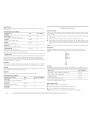
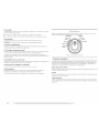
Maytag MED9700S - Electric Dryer Mode d'emploi
- Catégorie
- Laveuses sécheuses
- Taper
- Mode d'emploi

®
p C TM
ELECTRIC DRYER
USE & CARE GUIDE
p p
SECHEUSE ELECTRIQUE
GUIDE D'UTILISATION ET D'ENTRETIEN
FOR QUESTIONS ABOUT FEAI URES, OPERATION/PERFORMANCE, PARTS, ACCESSORIES OR SERVICE
CAI L: 1.800.688.9900
IN CANADA, CALl: 1.800.807.6777
VISIT OUR WEBSITE A1 WWW.MAYTAG.COM
IN CANADA, WWW.MAY lAG.CA
AU CANADA, POUR ASSISTANCE, INSI°ALI AFION OU SERVICE, COMPOSEZ I E : 1.800.807.6777
OIJ VISITEZ NOTRE SITE INTERNET
WWW.MAY lAG .CA
PARA OBTENER ACCESO AL MANUAl DE USO Y CUIDADO EN ESPAi'_OI, O PARA OBTENER INFORMACION ADICIONAI. ACERCA DE SU PRODUCTO, VISITE: WWW.MAYTAG.COM.
IENGA LISTO SU NUMERO DE MODEl O COMPLE[O. PUEDE ENCONTRAR El NUMERO DE MODEl O Y DE SERIE DENTRO DE LA CAVIDAD SUPERIOR DE LA PUERTA.
W10150616A

TABLE OF CONTENTS
DRYERSAFETY.......................................................................................................................... 3
INSTALLATION INSTRUCTIONS ............................................................................................. 4
Tools and Parts....................................................................................................................... 4
Optional Pedestal................................................................................................................... 4
kocation Requirements ........................................................................................................... 5
Electrical Requirements - U.S.A. Only .................................................................................... 7
Electrical Requirements - Canada Only .................................................................................. 9
Electrical Connection - U.S.A. Only ..................................................................................... 10
Venting Requirements .......................................................................................................... 16
Plan Vent System.................................................................................................................. 17
Install Vent System............................................................................................................... 19
Install leveling kegs ............................................................................................................. 19
Connect Vent ....................................................................................................................... 19
I.evel Dryer .......................................................................................................................... 19
ReverseDoor Swing ............................................................................................................. 20
Complete Installation ........................................................................................................... 22
DRYER USE.............................................................................................................................. 23
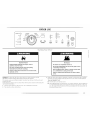
Starting Your Dryer............................................................................................................... 23
Stopping Your Dryer ............................................................................................................ 24
Pausing or Restarting............................................................................................................ 24
Control Locked..................................................................................................................... 24
Drying and Cycle Tips.......................................................................................................... 24
Status I.ights.......................................................................................................................... 25
Cycles .................................................................................................................................. 25
Additional Features.............................................................................................................. 26
Drying Rack ......................................................................................................................... 27
DRYERCARE........................................................................................................................... 28
Cleaning the Dryer ].ocation ................................................................................................ 28
Cleaning the I.int Screen ...................................................................................................... 28
Cleaning the Dryer interior ................................................................................................... 28
Removing Accumulated Lint ................................................................................................ 29
Vacation and Moving Care .................................................................................................. 29
Changing the Drum Eight..................................................................................................... 29
TROUBLESHOOTING ............................................................................................................. 30
ASSISTANCE or SERVICE....................................................................................................... 32
ACCESSORIES......................................................................................................................... 32
wArrANTY ............................................................................................................................ 33
TABLE DES MATIERES
S[_CURIT[_DE LA S[_CHEUSE................................................................................................... 34
INSTRUCTIONS D'INSTALLATION ....................................................................................... 36
Outillage et pi_ces ............................................................................................................... 36
Pi6destal facultatif ................................................................................................................ 5¢6
Exigences d'emplacement .................................................................................................... 37
Specifications _lectriques ..................................................................................................... 5¢9
Exigences concernant I'(_vacuation ...................................................................................... 40
Planification du syst6me d'6vacuation ................................................................................. 41
Installation du syst6me d'_vacuation .................................................................................... 43
Installation des pieds de nivellement .................................................................................... 43
Raccordement du conduit d'_vacuation ............................................................................... 44
Mise h niveau de la s(!cheuse............................................................................................... 44
Inversion du sens d'ouverture de la porte ............................................................................. 44
Achever I'installation ............................................................................................................ 46
UTILISATION DE LA SI_CHEUSE............................................................................................. 47
Mise en marche de la s_cheuse............................................................................................ 47
Arr&t de la s_cheuse............................................................................................................. 48
Pauseou remise en marche .................................................................................................. 49
Verrouillage des commandes ............................................................................................... 49
Conseils pour le s_chage et les programmes ........................................................................ 49
T_moins lumineux ................................................................................................................ 49
Programmes ......................................................................................................................... 50
Caract6ristiques suppl6mentaires ......................................................................................... 51
Grille de s_chage ................................................................................................................. 53
ENTRETIENDE LA S[_CHEUSE............................................................................................... 54
Nettoyage de I'emplacement de la se_cheuse........................................................................ 54
Nettoyage du filtre _charpie ................................................................................................ 54
Nettoyage de I'int6rieur de la s_cheuse................................................................................ 55
Retrait de la charpie accumul6e ........................................................................................... 55
Precautions _ prendre pour les vacances et avant un d_m_nagement .................................. 55
Changement de I'ampoule d'_clairage du tambour .............................................................. 55
DI_PANNAGE .......................................................................................................................... 56
ASSISTANCE OU SERVICE...................................................................................................... 58
ACCESSOIRES.......................................................................................................................... 58
GARANTIE ............................................................................................................................... 59
2 ii__i_iii¸iiiiiiiiiiiiiiiiiiiiiii!i!iiiiiiiiiiiiiiiiiiiiiiiiiiiiiiiiiiiiiiiiiiiiiiiiiiiiiiiiiiiiiiiiiiiiiiiiiiiiiiiiiiiiiiiiiiiiiiiiiiiiiiiiiiiiiiiiiiiiiiiiiiiiiiiiiiiiiiiiiiiiiiiiiiiiiiiiiiiiiiiiiiiiiiiiiiiiiiiiiiiiiiiiiiiiiiiiiiiiiiiiiiiiiiiiiiiiiiiiiiiiiiiiiiiiiiiiiiiiiiiiiiiiiiiiiiiiiiiiiiiiiiiiiiiiiiiiiiiiiiiiiiiiiiiiiiiiiiiiiiiiiiiiiiiiiiiiiiiiiiiiiiiiiiiiiiiiiiiiiiiiiiiiiiiiiiiiiiiiiiiiiiiiiiiiiiiiiiiiiiiiiiiiiiiiiiiiiiiiiiiiiiiiiiiiiiiiiiiiiiiiiiiiiiiiiiiiiiiiiiiiiiii_ii!ii:iiiiiiii:ii:iiiiiiii!iii!iiiiliiiiiiii!!iiii:iiiiiilii_!i!i!i!i!iii_!iiiiiiiiiiiiii:iillill:!iiiiii_iiiii

i_i_!iii_i_iiIi!iiiiIi!iiiiIi!iiiiIi!iiiiii!iiiiii!iiiiii!iiiiii!iiiiii!iiiiii!iiiiii!iiiiii!iiiiii!iiiiii!iiiiii!iiiiii!iiiiii!iiiiii!iiiiii!iiiiii!iiiiii!iiiiii!iiiiii!iiiiii!iiiiii!iiiiii!iiiiii!iiiiii!iiiiii!iiiiii!iiiiii!iiiiii!iiiiii!iiiiii!iiiiii!iiiiii!iiiiii!iiiiii!iiiiii!iiiiii!iiiiii!iiiiii!iiiiii!iiiiii!iiiiii!iiiiii!iiiiii!iiiiii!iiiiii!iiiiii!iiiiii!iiiiii!iiiiii!iiiiii_)!_}iiiii!!_!_!_!_!_!_!_!_!_!_!_!_i_¸ _ii_ i!i!_iii_1i_i_i_i_i_i_i_i_i_i_i_i_i_i_i_i_i_i_i_i_i_i_i_i_i_i_i_i_i_i_i_i_i_i_i_i_i_i_i_i_i_i_i_i_i_i_i_i_i_i_i_i_i_i_i_i_i_i_i_i_i_i_i_i_i_i_i_i_i_i_i_i_i_i_i_i_i_i_i_i_i_i_i_i_i_i_i_i_i_i_i_i_i_i_i_i_i_i_i_i_i_i_i_i_i_i_i_i_i_i_i_i_i_i_i_i_i_i_i_i_i_i!!!_iiiiiiiiiiiiiiiiiiiiiiiiiiii_:_i!i
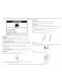
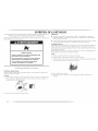
DRYER SAFETY
Your safety and the safety of others are very important.
We have provided many important safety messages in this manual and on your appliance. Always read and obey all safety
messages.
This is the safety alert symbol.
This symbol alerts you to potential hazards that can kill or hurt you and others.
All safety messages will follow the safety alert symbol and either the word "DANGER" or "WARNING."
These words mean:
You can be killed or seriously injured if you don't immediately
follow instructions.
You can be killed or seriously injured if you don't follow
instructions.
All safety messages will tell you what the potential hazard is, tell you how to reduce the chance of injury, and tell you what can
happen if the instructions are not followed.
S%
IMPORTANT SAFETY iNSTRUCTiONS
WARNING: To reduce the risk of fire, electric shock, or injury to persons when using the dryer, follow basic precautions,
including the following:
[] Read all instructions before using the dryer.
[] Do not place items exposed to cooking oils in your dryer.
Items contaminated with cooking oils may contribute to
a chemical reaction that could cause a load to catch fire.
[] Do not dry articles that have been previously cleaned in,
washed in, soaked in, or spotted with gasoline, dry-
cleaning solvents, or other flammable or explosive
substances as they give off vapors that could ignite or
explode.
[] Do not allow children to play on or in the dryer. Close
supervision of children is necessary when the dryer is
used near children.
[] Before the dryer is removed from service or discarded,
remove the door to the drying compartment.
[] Do not reach into the dryer if the drum is moving.
[] Do not install or store the dryer where it will be exposed
to the weather.
[] Do not tamper with controls.
[] Do not repair or replace any part of the dryer or attempt
any servicing unless specifically recommended in this
Use and Care Guide or in published user-repair
instructions that you understand and have the skills to
carry out.
[] Do not use fabric softeners or products to eliminate static
unless recommended by the manufacturer of the fabric
softener or product.
[] Do not use heat to dry articles containing foam rubber or
similarly textured rubber-like materials.
[] Clean lint screen before or after each load.
[] Keep area around the exhaust opening and adjacent
surrounding areas free from the accumulation of lint, dust,
and dirt.
[] The interior of the dryer and exhaust vent should be
cleaned periodically by qualified service personnel.
[] See installation instructions for grounding requirements.
SAVETHESEINSTRUCTIONS
.... 3

Gather the required tools and parts before starting installation. Read and follow the
instructions provided with any tools listed here•
• Flat-blade screwdriver
• #2 Phillips screwdriver
• Adjustable wrench that opens to 1"
(2.5 cm) or hex-head socket wrench
(for adjusting dryer feet)
• Wire stripper (direct wire installations)
• I.evel
• Vent clamps
• Caulking gun and compound (for
installing new exhaust vent)
• Tin snips/new vent installations/
• _/_"nut driver/recommended)
• [_pe measure
Are you placing the dryer on a pedestal? You have the option of purchasing pedestals of
different heights separately for this dryer. You may select a 10" (25.4 cm) pedestal or a
15.5' (39.4 cm) pedestal with a storage drawer• The pedestal will add to the total height of the
dryer for a total height of approximately 46" (116.8 cm) or 51.5' (130.8 cm/, respectively.
For a garage installation, you will need to place the 10' (25.4 cm) pedestal at least
9' (22.9 cm) above the floor. You will need to place the 15.5" (_¢9.4 cm) pedestal at least
3' (7.6 cm) above the floor.
Parts supplied
Remove parts packages from dryer drum. Check that all parts are included.
4 Low,ling legs
NOTE: Do not use leveling legs if installing the dryer on a pedestal.
Parts needed
Check local codes. Check existing electrical supply and venting. See "Electrical
Requirements" and "Venting Requirements" before purchasing parts.
• For close-clearance installations between 31.5' (80.01 cm) and 37' (93.98 cm), see "Plan
Vent System" section for venting requirements.
(9:3.98 era)
Mobile home installations require metal exhaust system hardware available for purchase from
the dealer from whom you purchased your dryer. For further information, please refer to the
"Assistance or Service" section.
If using a power supply cord:
Use a U[. listed power supply cord kit marked for use with clothes dryers. The kit should
contain:
• A UI. listed 30-amp power supply cord, rated 120/240 volt minimum. ]he cord should be
type SRD or SRDT and be at least 4 ft (1.22 m) long. ]he wires that connect to the dryer
must end in ring terminals or spade terminals with upturned ends.
• A UI. listed strain relief.
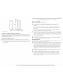
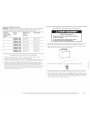
Optlonal pedestal f 1_._ /39.4 cm] model shown)
The pedestals are available in several colors.
lb order, call the dealer from whom you purchased your dryer or refer to the "Assistance or
Service" section.
Pedestal Height Color Part Number
10" (25.4 cm) White MHP1000SQO
10" (25.4 cm) Black MHP1000SB0
15.5" (39.4 cm) White MHP1500SQ0
15.5" (39.4 cm) Black MHP1500SB0
15.5" (39.4 cm) Pacific Blue MHP1500SK0
Stack Kit
Are you planning to stack your washer and dryer? To do so, you will need to purchase a Stack
Kit. [b order, call the dealer from whom you purchased your dryer or refer to the "Assistance
or Service" section. Ask for Part Number 8212640.

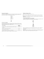
L( (._ {I( II l'ill;;"_,lli, II= .[ I,_ I ,_
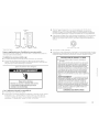
Dryer Dimensions
Explosion Hazard
Keep flammable materials and vapors, such as
gasoline, away from dryer.
Place dryer at least 18 inches (46 cm) above the floor
for a garage installation.
Falure to do so can result in death, explosion, or fire.
38,,/
(96.52cm)
/
{80crn) 27"
_ \_ (68.6 cm)
Yon will need
• A location that allows for proper exhaust installation. See "Venting Requirements."
• A separate 30-amp circuit.
• If you are using a power supply cord, a grounded electrical outlet located within 2 ft
(61 cm) of eitllev side of the @yet. See "Electrical Requirements."
• A sturdy floor to support the total dryer weight of 200 Ibs (90.7 kg). The combined weight
of a companion appliance should also be considered.
• A level floor with a maximum slope of 1" (2.5 cm) under entire dryer. If slope is greater
than 1" (2.5 cm), install Extended [Dryer Feet Kit, Part Number 279810. Clothes may not
tumble properly and automatic sensor cycles may not operate correctly if dryer is not
level.
• For a garage installation, you will need to place the dryer at least 18" (46 cm) above the
floor. If using a pedestal, you will need 18" (46 cm) to the bottom of the dryer.
Do not operate your dryer at temperatures below 45°F (7°C). At lower temperatures, the dryer
might not shut off at the end of an automatic cycle. This can result in longer drying times.
The dryer must not be installed or stored in an area where it will be exposed to water and/or
weather.
Check code requirements. Some codes limit, or do not permit, installation of the dryer in
garages, closets, mobile homes or sleeping quarters. Contact your local building inspector.
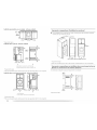
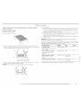
Installation clearances
The location must be large enough to allow the dryer door to open fully.
*Most installations require a minimum 5" (12.7 cm) clearance behind the dryer for the
exhaust vent with elbow. See "Venting Requirements."
Installation spacing for recessed area or closet installation
[he following spacing dimensions are recommended for this dryer. This dryer has been tested
for spacing of 0" (0 cm) clearance on the sides and rear. Recommended spacing should be
considered for the following reasons:
• Additional spacing should be considered for ease of installation and servicing.
• Additional clearances might be required for wall, door and floor moldings.
• Additional spacing should be considered on all sides of the dryer to reduce noise transfer.
• For closet installation, with a door, minimum ventilation openings in the top and bottom
of the door are required. [ ouvered doors with equivalent ventilation openings are
acceptable.
• Companion appliance spacing should also be considered.
Custom undercounter installation - Dryer only
9" ____,
(ocm)
38"rain.
(96.52 crn)
I"* ----_1_----27"--_ _ I"*
2.8cm n {68.6cm) 2.8cm
*Required spacing

Closet installation - Dryer only
I
IIII I I 24inY
I1°*1_ al,/2"_"ls"_*l
(2.5cm) (SOcrn)(12.7cm)
A
'-_" 3"*
(7.6crn)
A. Side view - closet or confined area
B.Closet door with wmts
* Required spacing
**For side or bottom venting, 0" (0 cm) spacing is allowed.
Recessed or closet installation - Dryer on pedestal
olo
- v
_1 _ 1¢ max?
$ IgIrff_.*
1"'1I_-- 31w'--_ls"**l
(2.5 era) (2.5 cm) (80 cm) {12.7 _m}
B
Recommended installation spacing for cabinet installation
• For cabinet installation, with a door, minimum ventilation openings in the top of the
cabinet are required.
T'* (17.8cm)
7"*(17.8cm)
I-
5"** 31Y£' 1"*
,Z_,
(22.9 cm)
1" 27" 1"
(12.7cm) (80.0 cm) (2.5cm) (2.5cm)(68.6 cm){2.6 cm)
*Required spacing
**For side or bottom venting, O" iO cm) spacing is allowed.
Recommended installation spacing for recessed or closet installation, with
stacked washer and dryer
The dimensions shown are for the recommended spacing.
1,, ,,--_,. 4(-._ 27,,,,,,,,,,,,,,,,-_1[_..-- 1,,
(2.5 cm) (68.6 cm) 3"* (7.6 cm)
48 in. 2 *
(319 cm 2)
T
o
-- __
Ac_
3"*(7.6cm)
24in.__
A. R(!c_!ss(z!c_ al(!a
B. Side view - closet or confined area
*Required spacing
**For side or bottom venting, 0" (0 cm) spacing is allowed.
(155cmz)
I i!_!iii¸
1"*{2.6crn)
*Required spachlg
_ ___ ........................ i iiiiiiiiiiiiiiiiiiiiiiiiii iiiiiiiiiiiiiiiiiiiiiiii/ !IZ/ 7i¸t: ii _"i/ii;;!;!;!;: iiiiiii! ii!¸¸ ii!¸¸¸¸¸¸¸¸¸¸¸ ....

*Required spacing
5"*
(12.7crn)
6"* (_S,2 cm)
76"
(193 crn) --
_-- 1" _ _- 27"-1_
(2.5¢m) 68.6¢m
Mobile home - Additional installation requirements
This dryer is suitable for mobile home installations. The installation must conform to the
Manufactured Home Construction and Safety Standard, Title 24 CFR, Part 3280 (formerly the
Federal Standard for Mobile Home Construction and Safety, Title 24, HUD Part 280) or
Standard CAN/CSA-Z240 MH.
Mobile home installations require:
• Metal exhaust system hardware, which is aw_ilable for purchase from your dealer.
• Special provisions must be made in mobile homes to introduce outside air into the dryer.
The opening (such as a nearby window) should be at least twice as large as the dryer
exhaust opening.
It is your responsibility
• lb contact a qualified electrical installer.
• lb be sure that the electrical connection is adequate and in conformance with the
National Electrical Code, ANSI/NFPA 70-latest edition and all local codes and
ordinances.
The National Electric Code requires a 4-wire power supply connection for homes built
after 1996, dryer circuits involved in remodeling after 1996, and all mobile home
installations.
A copy of the above code standards can be obtained from: National Fire Protection
Association, One Batterymarch Park, Quincy, MA 02269.
[b supply the required 3 or 4 wire, single phase, 120/240 volt, 60 Hz., AC only electrical
supply (or 3 or 4 wire, 120/208 volt electrical supply, if specified on the serial/rating plate)
on a separate 30-amp circuit, fused on both sides of the line. A time-delay fuse or circuit
breaker is recommended. Connect to an individual branch circuit. Do not have a fuse in
the neutral or grounding circuit.
Do not use an extension cord.
If codes permit and a separate ground wire is used, it is recommended that a qualified
electrician determine that the ground path is adequate.
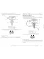
Electrical Connection
[b properly install your dryer, you must determine the type of electrical connection you will
be using and follow the instructions provided for it here.
• This dryer is manufactured ready to install with a C-wire electrical supply connection. The
neutral ground conductor is permanently connected to the neutral conductor (white wire)
within the dryer. If the dryer is installed with a 4-wire electrical supply connection, the
neutral ground conductor must be removed from the external ground connector (green
screw), and secured under the neutral terminal (center or white wire) of the terminal
block. When the neutral ground conductor is secured under the neutral terminal (center
or white wire) of the terminal block, the dryer cabinet is isolated from the neutral
conductor.
If local codes do not permit the connection of a neutral ground wire to the neutral wire,
see "Optional 3-wire connection" section.
A 4-wire power supply connection must be used when the appliance is installed in a
location where grounding through the neutral conductor is prohibited. Grounding
through the neutral is prohibited for (1) new branch-circuit installations, (2) mobile
homes, (3) recreational vehicles, and (4) areas where local codes prohibit grounding
through the neutral conductors.

If using a power supply cord:
Use a U[. listed power supply cord kit marked for use with clothes dryers. The kit should
contain:
[] A U] listed 30-amp power supply cord, rated 120/240 volt minimum. The cord should be
type SRD or SRDT and be at least 4 ft (1.22 m) long. The wires that connect to the dryer
must end in ring terminals or spade terminals with upturned ends.
[] A UL listed strain relief.
If your outlet looks like this:
4-wire" re'cept_cle' (14-30R)
Then choose a 4-wire power supply cord with ring or spade terminals and UI. listed strain
relief. The 4-wire power supply cord, at least 4 fl (1.22 m) long, must have four 10-gauge
copper wires and match a 4-wire receptacle of NEMA Type 14-30R. The ground wire (ground
conductor) may be either green or bare. The neutral conductor must be identified by a white
cover.
If your outlet looks like this:
49
3-wir_" r_'ceptacl_" (lO-30R)
Then choose a 3-wire power supply cord with ring or spade terminals and UL listed strain
relief. The 3-wire power supply cord, at least 4 ft (1.22 m) long, must have three 10-gauge
copper wires and match a 3-wire receptacle of NEMA t_/pe 10-30R.
If connecting by direct wire:
Power supply cable must match power supply (4-wire or 3-wire) and be:
[] Flexible armored cable or nonmetallic sheathed copper cable (with ground wire),
protected with flexible metallic conduit. All current-carrying wires must be insulated.
[] 10-gauge solid copper wire (do not use aluminum).
[] At least 5 ft (1.52 m) long.
GROUNDING INSTRUCTIONS
[] For a grounded, cord-connected dryer:
This dryer must be grounded. In the event of malfunction or
breakdown, grounding will reduce the risk of electric shock
by providing a path of least resistance for electric current.
This dryer uses a cord having an equipment-grounding
conductor and a grounding plug. The plug must be plugged
into an appropriate outlet that is properly installed and
grounded in accordance with all local codes and ordinances.
[] For a permanently connected dryer:
This dryer must be connected to a grounded metal,
permanent wiring system, or an equipment-grounding
conductor must be run with the circuit conductors and
connected to the equipment-grounding terminal or lead on
the dryer.
WARNING: Improper connection of the equipment-
grounding conductor can result in a risk of electlic shock.
Check with a qualified electrician or service representative
or personnel if you are in doubt as to whether the dryer is
properly grounded. Do not modify the plug on the power
supply cord: if it will not fit the outlet, have a proper outlet
installed by a qualified electrician.
SAVE THESE INSTRUCTIONS
8

.... _ • _ 51 ....
<,aada v
Electrical Shock Hazard
Plug into a grounded 4 prong outlet.
Failure to do so can result in death or electrical shock.
It is your responsibility
• ]b contact a qualified electrical installer.
• ]b be sure that the electrical connection is adequate and in conformance with the
Canadian Electrical Code, C22.1 -latest edition and all local codes. A copy of the above
codes standard may be obtained from: Canadian Standards Association, 178 Rexdale
Blvd., toronto, ON M9W 1R3 CANADA.
1o supply the required 4 wire, single phase, I20/240 volt, 60 Hz., AC only electrical
supply on a separate 30-amp circuit, fused on both sides of the line. A time-delay fuse or
circuit breaker is recommended. Connect to an individual branch circuit
[his dryer is equipped with a CSA International Certified Power Cord intended to be
plugged into a standard 14-%0R wall receptacle. The cord is 5 ft (1.52 m) in length. Be
sure wall receptacle is within reach of dryer's final location.
If you are using a replacement power supply cord, it is recommended that you use Power
Supply Cord Replacement Part Number 983131 7. For further information, please reference
the service numbers located in the "Assistance or Service" section.
GROUNDING INSTRUCTIONS
• For a grounded, cord-connected dryer:
This dryer must be grounded. In the event of malfunction or
breakdown, grounding will reduce the risk of electric shock
by providing a path of least resistance for electric current.
This dryer is equipped with a cord having an equipment-
grounding conductor and a grounding plug. The plug must
be plugged into an appropriate outlet that is properly
installed and grounded in accordance with all local codes
and ordinances.
WARNING: Improper connection of the equipment-
grounding conductor can result in a risk of electric shock.
Check with a qualified electrician or service representative
or personnel if you are in doubt as to whether the dryer is
properly grounded. Do not modify the plug provided with the
dryer: if it will not fit the outlet, have a proper outlet installed
by a qualified electrician.
SAVE THESE INSTRUCTIONS
4-wire" re'ceptacle 14-30R
• Do not use an extension cord.
S_

Power Supply Cord
Fire Hazard
Use a new UL listed 30 amp power supply cord.
Use a UL listed strain relief.
Disconnect power before making electrical connections.
Connect neutral wire (white or center wire) to center
terminal (silver).
Ground wire (green or bare wire) must be connected to
green ground connector.
Connect remaining 2 supply wires to remaining
2 terminals (gold).
Securely tighten all electrical connections.
Failure to do so can result in death, fire, or
electrical shock.
Direct Wire
Fire Hazard
Use 10 gauge solid copper wire.
Use a UL listed strain relief.
Disconnect power before making electrical connections.
Connect neutral wire (white or center wire) to center
terminal (silver).
Ground wire (green or bare wire) must be connected to
green ground connector.
Connect remaining 2 supply wires to remaining
2 terminals (gold).
Securely tighten all electrical connections.
Failure to do so can result in death, fire, or
electrical shock.
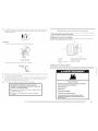
1. Disconnect power.
2. Remove the hold-down screw and terminal block cover.
z
/
A. Neutral ground wire
B. Fxternal ground conductor scr_'w
C. (o_'ntel; silver-colored te'rminal
block screw
D. 7_'rminalblock coverand hold-
dovvn S( F_'VV
3_ install strain relief.
Style 1: Power supply cord strain relief
• Remove the screws from a %" (1.9 cm) U[. listed strain relief (U[ marking on strain
relief). Put the tabs of the two clamp sections into the hole below the terminal block
opening so that one tab is pointing up and the other is pointing down, and hold in
place. Tighten strain relief screws enough to hold the two clamp sections together.
A. Strain r_'lief tab pointing Lip
B. Hole below tenTlinal block opening
C. Clamp section
D. Strain relief tab pointing down
10

Putpowersupplycordthroughthestrainrelief.Besurethatthewireinsulationonthe
powersupplycordisinsidethestrainrelief.Thestrainreliefshouldhaveatightfit
withthedryercabinetandbeinahorizontalposition.Donotfurthertightenstrain
reliefscrewsatthispoint.
Style 2: Direct wire strain relief
• Unscrew tile rer'nowtble conduit connector and any screws from a %" (1.9 cm) U[.
listed strain relief (UI. marking on strain relief). Put the threaded section of the strain
relief through the hole below the terminal block opening. Reaching inside the
terminal block opening, screw the removable conduit connector onto the strain relief
threads.
A
B
...................... C
A. RemovabJe conduit connector
B. Hol_' below terminal block opening
C. Strain relief thr_'ad_
• Put direct wire cable through the strain relief. ]he strain relief should have a tight fit
with the dryer cabinet and be in a horizontal position. Tighten strain relief screw
against the direct wire cable.
4. Now complete installation following instructions for your type of electrical connection:
4-wire (recommended)
3-wire (if 4-wire is not available)
Electrical Connection Options
If your home has: And you will be Go to Section ....
connecting to:
4_"_*'-w"_']"rereceptacle A U[. listed, 20/240- 4-wire connecti n
(NEMA Type 14-30R) volt minimum, Power supply cord
(_ 30 amp, clryer power
supply cord*
4-wire direct A fused disconnect or 4-wire connection:
circuit breaker box* Direct Wire
(12.7cm)
3-wire receptacle
(NEMA type 10-30R)
©
A UI. listed, 120/240-
volt minimum,
30-amp, dryer power
supply cord*
3-wire connection:
Power supply cord
3-wire direct A fused disconnect or 3-wire connection:
circuit breaker box* Direct Wire
*If local codes do not permit the connection of a cabinet-ground conductor to the neutral
wire, go to "Optional 3-wire connection" section.

4-wire connection: Power supply cord
IMPORTANT: A 4-wire connection is required for mobile homes and where local codes do
not permit the use of 3-wire connections.
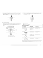
C D E G
1,
2.
A. 4-wire receptacle eNEMA type 14+30R)
B. 4-prong plug
C. Ground prong
D. Neutral prong
E. Spade tern'linal_ with upturned ends
F. Y+" ( 1.9 cn'l) Ut listed strain relief
G. Ring tenTlinab
Remove center silver-colored terminal block screw.
Remove neutral ground wire from external ground conductor screw. Connect neutral
ground wire and the neutral wire (white or center wire) of power supply cord under
center, silver-colored terminal block screw. Tighten screw.
A. Fxternal ground conductor screw - Dotted line shows position
of NEUTRAL ground wire" before being moved to center silver-
colored terminal block screw.
B. Center silver-colored tenTlinal block screw
C. Neutral ground wire
D. Neutral wire (white or center wire')
E. Y+" (t.9 cm) UI li_ted strain relief
3. Connect ground wire/green or [)are) of power supply cord to external ground conductor
screw. Tighten screw.
4,
A. External ground conductor screw
B. Ground wire (green or bare') of power supply cord
C. Y+" ( 1.9 cm) UI listed strain relief
D. Center silver-colored terminal block screw
E. Neutral ground wire"
I. Neutral wire (white or center wire')
Connect the other wires to outer terminal block screws. Tighten screws.
!! !!
5. Tighten strain relief screws.
6. Insert tab of terminal block cover into slot of dryer rear paneh Secure cover with hold-
down screw.
7. You have completed your electrical connection. Now go to "Venting Requirements."
4-wire connection: Direct wire
IMPORTANT: A 4-wire connection is required for mobile homes and where local codes do
not permit the use of 3-wire connections.
Direct wire cable must have 5 ft (1.52 m) of extra length so dryer can be moved if needed.
12

Strip 5" (12.7 cm) of outer covering from end of cable, leaving bare ground wire at 5"
(12.7 cm). Cut 11/2"(3.8 cm) from 3 remaining wires. Strip insulation back 1" (2.5 cm). Shape
ends of wires into a hook shape.
1"
When connecting to the terminal block, place the hooked end of the wire under the screw of
the terminal block (hook facing right), squeeze hooked end together and tighten screw, as
shown.
1.
2.
Remove center silver-colored terminal block screw.
Remove neutral ground wire from external ground conductor screw. Connect neutral
ground wire and place the hooked end (hook facing right) of the neutral wire (white or
center wire) of direct wire cable under the center screw of the terminal block. Squeeze
hooked ends together. Tighten screw.
Connect ground wire/green or bare) of direct wire cable to external ground conductor
screw. Tighten screw.
A. External ground conductor screw
B. Ground wire" (green or bare') of power supply cable
C. _" ( 1.9 cm) UL li_ted strain relie'f
D. C_ulter silver-colored terminal block scre'w
E. Neutral groutld wire"
f. Neutral wire twhite or cente'r wire)
Place the hooked ends of the other direct wire cable wires under the outer terminal [)lock
screws (hooks facing right). Squeeze hooked ends together. Tighten screws.
!! !!
5. Tighten strain relief screw.
6. insert tab of terminal block cover into slot of dryer rear panel. Secure cover with hold-
down screw.
7. You have completed your electrical connection. Now go to "Venting Requirements."
A. Yxternal ground conductor scre'w - Dotte'd line shows position of NEUTRAL
ground wire before" being n'loved to center silver-colored te'rP,'linal block screw.
B. C_'nter silver-colored te'rn'linal block screw
C. Neutral ground wire'
D. Neutral wire' (white or center wire')
E. Y#" (1.9 cm) UL listed strain reqief

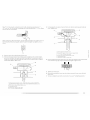
3-wire connection: Power supply cord
Use where local codes permit connecting cabinet-ground conductor to neutral wire.
A ....... I I
C G F
1,
2.
A. 3-wire receptacle tNEMA type 10-30t7)
8.3-wire plug
C. Neutral prong
D. _pade terminals with Lip turned ends
E. %" (1.9 crnJ U[ list_,d strain relief
f.Ring terminals
G. Neutral (white" or center wir_')
I.oosen or remove center silver-colored terminal [)lock screw.
Connect neutral wire (white or center wire) of power supply cord to the center, silver-
colored terminal screw of the terminal block. Tighten screw.
3. Connect the other wires to outer terminal block screws. Tighten screws.
!! !I
4. Tighten strain relief screws.
5. Insert tab of terminal block cover into slot of dryer rear paneh Secure cover with hold-
down screw.
6. You have completed your electrical connection. Now go to "Venting Requirements."
3-wire connection: Direct wire
Use where local codes permit connecting cabinet-ground conductor to neutral wire.
Direct wire cable must have 5 ft (1.52 rn) of extra length so dryer can be moved if needed.
Strip 3_/2'' (8.9 cm) of outer covering from end of cable. Strip insulation back 1" (2.5 cm). If
using 3-wire cable with ground wire, cut bare wire even with outer covering. Shape ends of
wires into a hook shape.
A. Fxte'rnal ground conductor screw
B. Neutral ground wir_"
C. Ce,nter silver-color_'d t_'rminal block screw
D. Neutral wire' lwhit_' or center wire')
E. _" : 1.9 cm) UZ listed strain reli_'f
3V¢
t_.9cm_
When connecting to the terminal block, place the hooked end of the wire under the screw of
the terminal block (hook facing right), squeeze hooked end together and tighten screw, as
shown.
14 _i__lllliiiiiiiiiJiilllllllllllllllllllllllllllllllllllllllllllllllllllllllllllllllllllllllllllllllllllllllllllllllllllllllllllllllllllllllllllllllllllllllllllllllllllllllllllllllllllllllllllllllllllllllllllllllllllllllllllllllllllllllllllllllllllllllllllllllllllllllllllllllllllllllllllllllllllllllllllllllllllllllllllllllllllllllllllllllllllllllllllllllllllllllllllllllllllllllllllllllllllllllllllllllllllllllllllllllllllllllllllllllllllllllllllllllllllllllllll_;lll_iiiiiili_!i_l_i_i_;i!il;::_lli;l;ii;ii_:ll_%i%li:_!i_iiilll_i_i_llll_l_llll_lll!..........

1.
2.
Loosen or remove center silver-colored terminal block screw.
Place the hooked end of the neutral wire (white or center wire) of direct wire cable under
the center screw of terminal block (hook facing right). Squeeze hooked end together.
Tighten screw.
A. External ground conductor screw
B.Neutral ground wire
C. Center silver-colored tenTlinal block screw
D. Neutral wire (white or center wire)
E. ¾" (1.9 cm) UL listed strain relief
Place the hooked ends of the other direct wire cable wires under the outer terminal block
screws (hooks facing right). Squeeze hooked ends together. Tighten screws.
! I
4. Tighten strain relief screw.
5. Insert tab of terminal block cover into slot of dryer rear panel. Secure cover with hold-
(JOWl] screw.
6. You have completed your electrical connection. Now go to "Venting Requirements."
Optional 3-wire connection
Use for direct wire or power supply cord where local codes do not permit connecting
cabinet-ground conductor to neutral wire.
1. Remove center silver-colored terminal block screw.
2. Remove neutral ground wire from external ground conductor screw. Connect neutral
ground wire and the neutral wire (white or center wire) of power supply cord/cable under
center, silver-colored terminal block screw. Tighten screw.
E
4,
5.
jF
//,'/
A. f xternal ground conductor screw
B. C_'nter silver-colored terminal block screw
C. Neutral ground wire
D. Neutral wire (white or center wire)
E._" t 1.9 cm) UL li_ted strain relief
E Grounding path determined by a qualified electrician
Connect the other wires to outer terminal block screws. Tighten screws.
I I
--ram
Tighten strain relief screws.
Connect a separate copper ground wire from the external ground conductor screw to an
adequate ground.
Insert tab of terminal block cover into slot of dryer rear panel. Secure cover with hold-
down screw.

FireHazard
Useaheavy metal vent.
Do not use a plastic vent.
Do not use a metal foil vent.
Failure to follow these instructions can result in death
or fire.
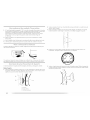
Rigid metal vent
• For best drying performance, rigid metal vents are recommended.
• Rigid metal vent is recommended to avoid crushing and kinking.
Flexible metal vent
• Flexible metal vents are acceptable only if accessible for cleaning.
• Flexible metal vent must be fully extended and supported when the dryer is in its final
location.
• Remove excess flexible metal vent to avoid sagging and kinking that may result in
reduced airflow and poor performance.
• Do not install flexible metal vent in enclosed walls, ceilings or floors.
Elbows
45 ° elbows provide better airflow than 90 ° elbows.
WARNING: lb reduce the risk of fire, this dryer MUST BE EXHAUSTED OUTDOORS.
IMPORTANT: Observe all governing codes and ordinances.
The dryer exhaust must not be connected into any gas vent, chimney, wall, ceiling or a
concealed space of a building.
If using an existing vent system Clamps
• Clean lint from the entire length of the system and make sure exhaust hood is not plugged •
with lint. •
• Replace any plastic or metal foil vent with rigid or flexible heavy metal vent.
• Review Vent system chart. Modify existing vent system if necessary to achieve the best
drying performance.
If this is a new vent system
Vent material
• Use a heavy metal vent. Do not use plastic or metal foil vent.
• 4" (10.2 cm) heavy metal exhaust vent and clamps must be used.
4" ( 10.2 cm) heavy metal exhaust vent
Vent products can be purchased from your dealer or by railing Maytag Services. For more
information, see the "Assistance or Service" section.
Good Better
Use clamps to seal all joints.
Exhaust vent must not be connected or secured with screws or other fastening devices
that extend into the interior of the duct. Do not use duct tape.
Clamp
Exhaust
Recommended hood styles are shown here.
B
r_4,, _-_
(10.2 cm)
A. Louver_'d hood style
B.Box hood style
16

[he angled hood style (shown here) is acceptable.
4"
(10.2 c__
If_ 21/2,'
(6.4 cm)
• An exhaust hood should cap the vent to keep rodents and insects from entering the home.
• Exhaust hood must be at least 12" (30.5 cm) from the ground or any object that may be in
the path of the exhaust (such as flowers, rocks or bushes, snow line, etc./.
• Do not use an exhaust hood with a magnetic latch.
improper venting can cause moisture and lint to collect
indoors, which may result in:
[] Moisture damage to woodwork, furniture, paint, wallpaper,
carpets, etc.
[] Housecleaning problems and health problems.
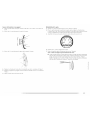
Choose your exhaust installation type
Recommended exhaust installations
Typical installations vent the dryer from the rear of the dryer. Other installations are possible.
B
A
............... F
......................................G
Optional exhaust installations
This dryer can be converted to exhaust out the right side, left side or through the bottom. If
you prefer, you may contact your local dealer to have the dryer converted.
Fire Hazard
Cover unused exhaust holes with one of the
following kits:
279818 (white)
279820 (black)
280102 (pacific blue)
Contact your local dealer.
Failure to follow these instructions can result in death,
fire, electrical shock, or serious injury.
C
A. Standard rear offset exhaust h_stallation
B. [eft or right side' exhaust installation
C. Bottom exhaust installation
A. Dryer
B. Hbow
C. Wall
D. £xhaust hood
E. Clamps
£ Rigid metal or flexible metal vent
G. Vent length necessary to connect elbows
H. Fxhaust outlet

Alternate installations for close clearances
Venting systems come ill many varieties. Select the type best for your installation. Two close-
clearance installations are shown. Refer to the manufacturer's instructions.
f •
i
A
aL_[ =---_
_===_f../,
V,';'"
i,';"
X I
A. Over-the-top installation (also available with one offset elbow)
B. P_riscope h_stallation
NOTE: The following kits for close clearance alternate installations are available for purchase.
Please see the "Assistance or Service" section to order.
• Over-the-Top Installation:
Part Number 4"_96028
• Periscope Installation (For use with dryer vent to wall vent mismatch/:
Part Number 4396037 - 0" (0 cm) to 18" (45.72 cm) mismatch
Part Number 4396011 - 18" (45.72 cm) to 29" (73.66 cm) mismatch
Part Number 4396014 - 29" (73.66 cm) to 50" (127 cm) mismatch
Special provisions for mobile home installations
The exhaust vent must be securely fastened to a noncombustible portion of the mobile home
structure and must not terminate beneath the mobile home. lerminate the exhaust vent
outside.
Determine vent path
• Select the route that will provide the straightest and most direct path outdoors.
• Plan the installation to use the fewest number of elbows and turns.
• When using elbows or making turns, allow as much room as possible.
• Bend vent gradually to avoid kinking.
• Use the fewest 90 ° turns possible.
Determine vent length and elbows needed for best drying performance
• Use the following Vent system chart to determine type of vent material and hood
combinations acceptable to use.
NOTE: Do not use vent runs longer than those specified in the Vent system chart. Exhaust
systems longer than those specified will:
• Shorten the life of the dryer.
• Reduce performance, resulting in longer drying times and increased energy usage.
[he Vent system chart provides venting requirements that will help to achieve the best drying
performance.
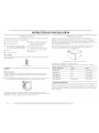
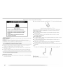
Vent system chart
NOTE: Side and bottom exhaust installations have a 90 ° turn inside the dryer. Io determine
maximum exhaust length, add one 90° turn to the chart.
Number of 90 ° Type of vent Box or Iouvered Angled hoods
turns or elbows hoods
0 Rigid metal 64 ft (20 rn) 58 ft (17.7 rn)
Flexible metal 36 ft (11 m/ 28 ft 18.5 m/
1 Rigid metal 54 ft (I 6.5 m) 48 ft (14.6 m)
Flexible metal 31 ft (9.4 m) 23 ft (7 m)
2 Rigid metal 44 ft (13.4 m) 38 ft (11.6 m)
Flexible metal 27 ft (8.2 m) 19 ft (5.8 m)
3 Rigid metal 35 ft (10.7 m) 29 ft (8.8 m)
Flexible metal 25 ft (7.6 m) 17 ft (5.2 m)
4
Rigid metal 27 ft (8.2 m) 21 ft (6.4 m)
Flexible metal 23 ft 17 m) 15 ft (4.6 m)
18

1. install exhaust hood. Use caulking compound to seal exterior wall opening around
exhaust hood.
2. Connect vent to exhaust hood. Vent must fit inside exhaust hood. Secure vent to exhaust
hood with 4' (10.2 cm) clamp.
3. Run vent to dryer location. Use the straightest path possible. See "Determine vent path" in
"Plan Vent System." Avoid 90° turns. Use clamps to seal all joints. Do not use duct tape,
screws or other fastening devices that extend into the interior of the vent to secure vent.
Excessive Weight Hazard
Use two or more people to move and install dryer.
Failure to do so can result in back or other injury.
1. lb protect the floor, use a large flat piece of cardboard from the dryer carton. Place
cardboard under the entire back edge of the dryer.
2. Firmly grasp the body of the dryer (not the console panel), Gently lay the dryer on the
cardboard. See illustration.
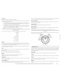
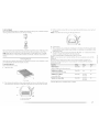
Examine the leveling legs. Find the diamond marking.
4. Screw the legs into the leg holes by hand. Use a wrench to finish turning the legs until the
diamond marking is no longer visible.
5. Place a carton corner post from dryer packaging under each of the 2 dryer back corners.
Stand the dryer up. Slide the dryer on the corner posts until it is close to its final location.
Leave enough room to connect the exhaust vent.
1. Using a 4' (10.2 cm) clamp, connect vent to exhaust outlet in dryer. If connecting to
existing vent, make sure the vent is clean. The dryer vent must fit over the dryer exhaust
outlet and inside the exhaust hood. Check that the vent is secured to exhaust hood with a
4" (10.2 cm) clamp.
2. Move dryer into its final location. Do not crush or kink vent.
3. (On gas models) Check that there are no kinks in the flexible gas line.
4-. Once the exhaust vent connection is made, remove the corner posts and cardboard.
, ....
Check the levelness of the dryer. Check levelness first side to side, then front to back.
If the dryer is not level, prop up the dryer using a wood block. Use a wrench to adjust the legs
up or down and check again for levelness.
!!{lll{l_i_!_!!iii!iiii_ii!!iiiiiiiiiiiiiiiiiiii_{{!!_!_i_!_!_!_!i{ii_i{{i_i{{i_i{{i_i{{i_i{{i_i{{i_i{{i_i{I i_,!!S!_{i!ii;::!!iSi! 19

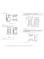
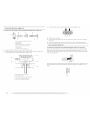
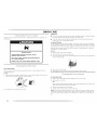
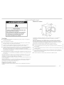
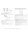
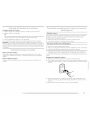
You can change your door swing from a right-side opening to a left-side opening, if desired. 4. Remove the 6 screws to release the outer door assembly from the inner door assembly
/see illustration). [t is important that you remove only the 6 indicated screws.
Remove the door
1. Open the dryer door. Remove the 4 screws that hold the door hinge on the front panel of
the dryer. I.oosen, but do not remove, the screw with the top keyhole opening last (second
from the top).
/
2,
3.
A. Dryer
B.Do not remove.
C. Dryer door
lift and pull forward on the door so that the keyhole clears the screw head. Remove the
door.
lay the dryer door on a flat, protected surface with the inside door assembly facing up.
Remove the last screw from Step 1. Remove the 2 screws holding the handle to the door.
5,
lift the inner door assembly off of the outer door assembly. Unsnap the handle from the
outer door assembly, move it to the other side, and snap in. Set the outer door assembly
aside.
-\
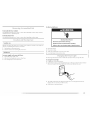
Reverse the hinge and hinge bracket
1. Place the inner door, screw head side up, on the work surface.
2. Remove the 4 screws that hold the hinge to the door.
20
La page charge ...
La page charge ...
La page charge ...
La page charge ...
La page charge ...
La page charge ...
La page charge ...
La page charge ...
La page charge ...
La page charge ...
La page charge ...
La page charge ...
La page charge ...
La page charge ...
La page charge ...
La page charge ...
La page charge ...
La page charge ...
La page charge ...
La page charge ...
La page charge ...
La page charge ...
La page charge ...
La page charge ...
La page charge ...
La page charge ...
La page charge ...
La page charge ...
La page charge ...
La page charge ...
La page charge ...
La page charge ...
La page charge ...
La page charge ...
La page charge ...
La page charge ...
La page charge ...
La page charge ...
La page charge ...
La page charge ...
-
 1
1
-
 2
2
-
 3
3
-
 4
4
-
 5
5
-
 6
6
-
 7
7
-
 8
8
-
 9
9
-
 10
10
-
 11
11
-
 12
12
-
 13
13
-
 14
14
-
 15
15
-
 16
16
-
 17
17
-
 18
18
-
 19
19
-
 20
20
-
 21
21
-
 22
22
-
 23
23
-
 24
24
-
 25
25
-
 26
26
-
 27
27
-
 28
28
-
 29
29
-
 30
30
-
 31
31
-
 32
32
-
 33
33
-
 34
34
-
 35
35
-
 36
36
-
 37
37
-
 38
38
-
 39
39
-
 40
40
-
 41
41
-
 42
42
-
 43
43
-
 44
44
-
 45
45
-
 46
46
-
 47
47
-
 48
48
-
 49
49
-
 50
50
-
 51
51
-
 52
52
-
 53
53
-
 54
54
-
 55
55
-
 56
56
-
 57
57
-
 58
58
-
 59
59
-
 60
60


Maytag MED9700S - Electric Dryer Mode d'emploi
- Catégorie
- Laveuses sécheuses
- Taper
- Mode d'emploi
dans d''autres langues
Documents connexes
-
Maytag Epic MED9800TK Mode d'emploi
-
-
-
-
-
-
-
-
-