Yamaha YHT-494 Le manuel du propriétaire
- Taper
- Le manuel du propriétaire

Home Theater Package
Pack Numérique Home Cinéma
YHT-494
(HTR-3063 + NS-BR300 +
NS-B285 + NS-SW280)
Owner’s Manual
Mode d’emploi
UC
English Français

i En
1. Read these instructions.
2. Keep these instructions.
3. Heed all warnings.
4. Follow all instructions.
5. Do not use this apparatus near water.
6. Clean only with dry cloth.
7. Do not block any ventilation openings. Install in accordance
with the manufacturer’s instructions.
8. Do not install near any heat sources such as radiators, heat
registers, stoves, or other apparatus (including amplifiers)
that produce heat.
9. Do not defeat the safety purpose of the polarized or
grounding-type plug. A polarized plug has two blades with
one wider than the other. A grounding type plug has two
blades and a third grounding prong. The wide blade or the
third prong are provided for your safety. If the provided plug
does not fit into your outlet, consult an electrician for
replacement of the obsolete outlet.
10. Protect the power cord from being walked on or pinched
particularly at plugs, convenience receptacles, and the point
where they exit from the apparatus.
11. Only use attachments/accessories specified by the
manufacturer.
12. Use only with the cart, stand, tripod, bracket,
or table specified by the manufacturer, or sold
with the apparatus. When a cart is used, use
caution when moving the cart/apparatus
combination to avoid injury from tip-over.
13. Unplug this apparatus during lightning
storms or when unused for long periods of time.
14. Refer all servicing to qualified service personnel. Servicing
is required when the apparatus has been damaged in any way,
such as power-supply cord or plug is damaged, liquid has
been spilled or objects have fallen into the apparatus, the
apparatus has been exposed to rain or moisture, does not
operate normally, or has been dropped.
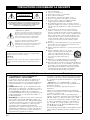
IMPORTANT SAFETY INSTRUCTIONS
CAUTION
RISK OF ELECTRIC SHOCK
DO NOT OPEN
CAUTION: TO REDUCE THE RISK OF ELECTRIC
SHOCK, DO NOT REMOVE COVER (OR BACK).
NO USER-SERVICEABLE PARTS INSIDE. REFER
SERVICING TO QUALIFIED SERVICE PERSONNEL.
• Explanation of Graphical Symbols
The lightning flash with arrowhead symbol, within an
equilateral triangle, is intended to alert you to the
presence of uninsulated “dangerous voltage” within the
product’s enclosure that may be of sufficient magnitude
to constitute a risk of electric shock to persons.
The exclamation point within an equilateral triangle is
intended to alert you to the presence of important
operating and maintenance (servicing) instructions in
the literature accompanying the appliance.
IMPORTANT
Please record the serial number of this unit in the space below.
MODEL:
Serial No.:
The serial number is located on the rear of the unit. Retain this
Owner’s Manual in a safe place for future reference.
FCC INFORMATION (for US customers)
1 IMPORTANT NOTICE: DO NOT MODIFY THIS
UNIT!
This product, when installed as indicated in the instructions
contained in this manual, meets FCC requirements.
Modifications not expressly approved by Yamaha may void
your authority, granted by the FCC, to use the product.
2IMPORTANT: When connecting this product to
accessories and/or another product use only high quality
shielded cables. Cable/s supplied with this product MUST be
used. Follow all installation instructions. Failure to follow
instructions could void your FCC authorization to use this
product in the USA.
3 NOTE: This product has been tested and found to comply
with the requirements listed in FCC Regulations, Part 15 for
Class “B” digital devices. Compliance with these
requirements provides a reasonable level of assurance that
your use of this product in a residential environment will not
result in harmful interference with other electronic devices.
This equipment generates/uses radio frequencies and, if not
installed and used according to the instructions found in the
users manual, may cause interference harmful to the operation
of other electronic devices.
Compliance with FCC regulations does not guarantee that
interference will not occur in all installations. If this product
is found to be the source of interference, which can be
determined by turning the unit “OFF” and “ON”, please try
to eliminate the problem by using one of the following
measures:
Relocate either this product or the device that is being
affected by the interference.
Utilize power outlets that are on different branch (circuit
breaker or fuse) circuits or install AC line filter/s.
In the case of radio or TV interference, relocate/reorient the
antenna. If the antenna lead-in is 300 ohm ribbon lead,
change the lead-in to coaxial type cable.
If these corrective measures do not produce satisfactory
results, please contact the local retailer authorized to
distribute this type of product. If you can not locate the
appropriate retailer, please contact Yamaha Electronics
Corp., U.S.A. 6660 Orangethorpe Ave., Buena Park, CA
90620.
The above statements apply ONLY to those products
distributed by Yamaha Corporation of America or its
subsidiaries.

ii En
English
Please read the following operating precautions before use. Yamaha will not be held responsible for any damage and/or injury caused by
not following the cautions below.
1. To assure the finest performance, please read this manual
carefully. Keep it in a safe place for future reference.
2. Install the speakers in a cool, dry, clean place – away from
windows, sources of heat, sources of excessive vibration,
dust, moisture or cold. Avoid sources of electrical humming
(e.g., transformers and motors). To prevent fire or electric
shock, do not expose the speakers to rain or water.
3. To prevent the enclosure from warping or discoloring, do not
expose the speakers to direct sunlight or excessive humidity.
4. Avoid installing the speakers where foreign objects may fall
onto them and/or where they may be exposed to liquid
dripping or splashing.
5. Do not place the following objects on top of the speakers:
– Other components, as they might damage or discolor the
surface of the speakers.
– Burning objects (e.g., candles), as they might cause fire,
damage to the speakers or personal injury.
– Containers of liquid, as they might spill and cause electric
shock to the user or damage to the speakers.
6. Do not place the speakers where they are liable to be knocked
over or struck by falling objects. Stable placement will also
ensure better sound performance.
7. Placing the speakers on the same shelf or rack as the
turntable can result in feedback.
8. Any time you note distortion, reduce the volume control on
your amplifier to lower setting. Never allow your amplifier to
be driven into “clipping”. Otherwise, the speakers may be
damaged.
9. When using an amplifier with a rated output power higher
than the nominal input power of the speakers, care should be
taken not to exceed the maximum input of the speakers.
10. Do not attempt to clean the speakers with chemical solvents
as this might damage the finish. Use a clean, dry cloth.
11. Do not attempt to modify or fix the speakers. Contact
qualified Yamaha service personnel when service is needed.
The cabinet should never be opened for any reason.
12. Be sure to read the “Troubleshooting” section regarding
common operating errors before concluding that the speakers
are faulty.
13. Secure placement or installation is the owner’s
responsibility. Yamaha is not liable for accidents caused
by improper placement or installation of speakers.
For NS-SW280
1. Do not operate this unit upside down. It may overheat,
possibly causing damage.
2. Do not use excessive force on switches, controls or
connection wires. When moving this unit, first disconnect the
power plug and the wires connected to other equipment.
Never pull the wires themselves.
3. Never put a hand or a foreign object into the port located on
the right side of this unit. When moving this unit, do not hold
the port, as it might cause personal injury and/or damage to
this unit.
4. Since this unit has a built-in power amplifier, heat radiates
from the rear panel. Place the unit away from walls, allowing
at least 20 cm (8") of space above, behind and on both sides
of the unit to prevent fire or damage. Furthermore, do not
position the unit with the rear panel facing down on the floor
or other surfaces.
5. When using a humidifier, be sure to avoid condensation
inside this unit by allowing enough space around the unit and
avoiding excess humidification. Condensation might cause
fire, damage to the unit, and/or electric shock.
6. Do not cover the rear panel of this unit with a newspaper,
tablecloth, curtain, etc. to avoid obstructing heat radiation. If
the temperature inside the unit rises, it may cause fire,
damage to the unit, or personal injury.
7. Do not plug this unit into a wall outlet until all connections
are complete.
8. The voltage to be used must match that specified on the rear
panel. Using this unit with a voltage higher than specified is
dangerous and may cause fire, damage to the unit, and/or
personal injury. Yamaha is not responsible for damage result-
ing from use of this unit with a voltage other than specified.
9. Super-bass sound reproduced by this unit may cause a
turntable to generate audio feedback. In this case, move the
unit away from the turntable.
10. This unit may be damaged if certain sounds are continuously
output at high volume level. For example, if 20 Hz–50 Hz
sine waves from a test disc or bass sounds from an electronic
instrument, etc. are continuously output, or if a turntable
stylus touches the surface of a disc, reduce the volume level
to prevent the unit from being damaged.
11. If you hear distorted noise (i.e., unnatural, intermittent
“rapping” or “hammering” sounds) from this unit, reduce the
volume level. Extremely loud movie soundtrack low
frequency, bass-heavy sounds, or similarly loud popular
music passages can damage this unit.
12. Vibration generated by super-bass sound may distort images
on a TV. In this case, move the unit away from the TV set.
13. When disconnecting the power cord from the wall outlet,
grasp the plug; do not pull the cord.
14. When you plan not to use this unit for a long period of time
(i.e. vacation, etc.), disconnect the AC power plug from the
wall outlet.
15. Install this unit near the wall outlet and where the AC power
plug can be reached easily.
Precautions
WARNING
TO REDUCE THE RISK OF FIRE OR ELECTRIC SHOCK,
DO NOT EXPOSE THIS APPLIANCE TO RAIN OR
MOISTURE.

iii En
Precautions
Yamaha and the Electronic Industries
Association’s Consumer Electronics Group want
you to get the most out of your equipment by
playing it at a safe level. One that lets the sound
come through loud and clear without annoying
blaring or distortion – and, most importantly,
without affecting your sensitive hearing. Since hearing damage
from loud sounds is often undetectable until it is too late, Yamaha
and the Electronic Industries Association’s Consumer Electronics
Group recommend you to avoid prolonged exposure from
excessive volume levels.
This unit is not disconnected from the AC power source as long
as it is connected to the wall outlet, even if this unit itself is
turned off. In this state, this unit is designed to consume a very
small quantity of power.
FOR CANADIAN CUSTOMERS
To prevent electric shock, match wide blade of plug to wide
slot and fully insert.
This Class B digital apparatus complies with Canadian
ICES-003.
We Want You Listening For A Lifetime

1 En
English
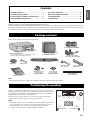
Thank you for choosing the Yamaha YHT-494 Home Theater Package.
The Yamaha YHT-494 Home Theater Package includes everything you need to add great sound to your home theater. By following
the instructions in this manual, you’ll have your home theater set up in no time and be enjoying music and movies like never before.
See also the AV Receiver’s owner’s manual for full instructions and precautions for AV Receiver.
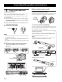
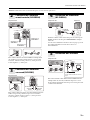
Make sure the package contains the following items.
Note
• Only the items required to complete the instalation explained in this manual are shown here.
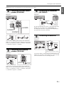
Before you connect the speakers, place each speaker in its respective location.
Speaker positioning is very important as it affects the overall sound quality of the
system. Place the speakers in locations that will optimize the sound quality at
your listening position. Refer to the illustration.
The position of the subwoofer is not as critical as the position of the other
speakers because sub-bass sounds are not very directional.
Notes
• Placing the speakers too close to a CRT-type TV may impair the picture color
or cause a buzzing noise. In this case, move the speakers at least 20 cm (8")
away from the TV. This is not an issue with LCD and plasma TVs.
• See page 7 for information on wall-mounting the speakers.
Package contents
Contents
Package contents.................................................1
Positioning the speakers ....................................1
Connecting the speakers and antennas ..........2
Connecting AV components ..............................4
Using the subwoofer............................................6
Wall-mounting the speakers..............................7
Troubleshooting...................................................8
Specifications........................................................8
VIDEO
AUX
PHONES
SILENT
CINEMA
TONE
CONTROL
STRAIGHT
VOLUME
TV
BD
DVD
CD
RADIO
INPUT
PR
OGRAM
SCENE
VIDEO
AUDIO
PORT
ABLE
LR
INFO
MEMORY
PRESET
FM AM
TUNING
YHT-494
AV Receiver (HTR-3063)*
* See the AV Receiver’s owner’s manual for a list of
the items supplied with the AV Receiver.
Subwoofer (NS-SW280)
Surround speakers (NS-B285)
AM antenna FM antenna
Stands and screws for
surround speakers (NS-B285)
Subwoofer cable
5 m (16 ft.) x1
Speaker cable
25 m (82 ft.) x1
Front/center speaker (NS-BR300)
Mounting template
for front/center
speaker (NS-BR300)
Stands and screws
for front/center
speaker (NS-BR300)
Non-skid pads
for front/center
speaker (NS-BR300)
Owner’s manual
Positioning the speakers
Subwoofer
Surround rightSurround left
Front/
center

2 En
Once you’ve positioned the speakers, you’ll need to cut the 25-
meter (82 ft.) speaker cable to make three cables for
connecting the front/center speaker and two cables for the
surround speakers.
1 Cut the included speaker cable to suitable lengths
for the front/center speaker and surround speakers.
You need five cables.
2 Remove about 10 mm (3/8") of insulation from the
end of each speaker cable.
3 Twist the bare wires tightly.
Notes
• Make the speaker cables as short as possible. Do not bundle
or roll up excess cable.
• Twist the bare wires tightly so the individual strands are not
splayed.
• Be careful not to injure yourself while preparing the speaker
cables.
4 Connect the speaker cables to the front/center
speaker (NS-BR300) and surround speakers
(NS-B285).
■ Attaching the speaker stands
• Surround speakers (NS-B285)
Attach the included speaker stands with screws when placing
the surround speakers on a flat surface, as shown below.
• Front/center speaker (NS-BR300)
If you place the front/center speaker (NS-BR300) at the base of
your TV, attach the included stands. If you use it without the
stands, affix the included non-skid pads.
Connecting the speakers and antennas
1
Preparing the cables and
speakers
Good No Good
10 mm (3/8")
NS-B285
(surround speakers)
NS-BR300
(front/center speaker)
Screw for
the NS-B285
speaker stands
Non-skid pads
550 mm (21-5/8")
695 mm (27-3/8")
82 mm
(3-1/4")
97 mm
(3-7/8")
Stand
Attaching the stands
On the rear of the front/center speaker (NS-BR300), there
are four screw holes at each end for attaching the stands at
a suitable height and width for your TV.
Note
Make sure the front/center speaker does not obstruct the
remote control sensor on the front of your TV.
Affixing the non-skid pads
Screw for the
NS-BR300 stands

Connecting the speakers and antennas
3 En
English
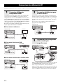
Caution: Disconnect all components from AC outlets before proceeding.
Connect the NS-BR300 speaker cables to the AV Receiver.
Make sure you connect the speaker with the correct polarity:
positive (+) terminals to positive (+) terminals, and negative
(–) terminals to negative (–) terminals.
Connect the surround speaker cables to the AV Receiver.
Make sure you connect the speakers with the correct polarity:
positive (+) terminals to positive (+) terminals, and negative
(–) terminals to negative (–) terminals.
Use the included subwoofer cable to connect the subwoofer’s
INPUT jack to the AV Receiver’s SUBWOOFER jack.
See “Using the subwoofer” on page 6 for more information
about the subwoofer and its operation.
Connect the AM loop antenna and indoor FM antenna to the
AV Receiver, as shown. See the AV Receiver’s owner’s manual
for more information about connecting antennas.
2
Connecting the front/center
speaker (NS-BR300)
3
Connecting the surround
speakers (NS-B285)
ANTENNA
FM
GND
AM
COMPONENT
VIDEO
P
R
P
B
Y
OPTICAL
(
TV
)
A
V 1
AV 2
AV 3
AV 4
AV 5
AUDIO 1
AUDIO 2
COAXIAL
(
CD
)
COAXIAL
OPTICAL
VIDEO
CENTER
SURROUND
HDMI 1
(
BD/DVD
)
HDMI 2 HDMI 3
HDMI 4
FRONT
COMPONENT
VIDEO
MONITOR OUT
P
R
P
B
Y
HDMI
OUT
MONITOR OUT
AV
OUT
SUBWOOFER
AUDIO
OUT
SPEAKERS
22
33
11
AV Receiver
To R terminals
of the NS-BR300
To L terminals
of the NS-BR300
To C terminals
of the NS-BR300
ANTENNA
FM
GND
AM
COMPONENT
VIDEO
P
R
P
B
Y
OPTICAL
(
TV
)
AV 1
AV 2
AV 3
AV 4
AV 5
AUDIO 1
AUDIO 2
COAXIAL
(
CD
)
COAXIAL
OPTICAL
VIDEO
CENTER
HDMI 1
(
BD/DVD
)
HDMI 2 HDMI 3
HDMI 4
FRONT
COMPONENT
VIDEO
MONITOR OUT
P
R
P
B
Y
HDMI
OUT
MONITOR OUT
AV
OUT
SUBWOOFER
AUDIO
OUT
SPEAKERS
SURROUND
22
33
11
AV Receiver
To surround
right speaker
To surround
left speaker
4
Connecting the subwoofer
(NS-SW280)
5
Connecting the antennas
ANTENNA
FM
GND
AM
COMPONENT
VIDEO
P
R
P
B
Y
OPTICAL
(
TV
)
AV
1
AV
2
AV
3
AV
4
A
V 5
AUDIO 1
A
UDIO 2
COAXIAL
(
CD
)
COAXIAL
OPTICAL
VIDEO
CENTER
SURROUND
HDMI 1
(
BD/DVD
)
HDMI 2 HDMI 3
HDMI 4
FRONT
COMPONENT
VIDEO
MONITOR OUT
P
R
P
B
Y
HDMI
OUT
MONITOR OUT
AV
OUT
SUBWOOFER
AUDIO
OUT
SPEAKERS
SUBWOOFER
AV Receiver Subwoofer
Subwoofer
cable
ANTENNA
FM
GND
AM
COMPONENT
VIDEO
P
R
P
B
Y
OPTICAL
(
TV
)
AV 1
AV 2
AV 3
AV 4
AV 5
AUDIO 1
AUDIO 2
COAXIAL
(
CD
)
COAXIAL
OPTICAL
VIDEO
CENTER
SURROUND
HDMI 1
(
BD/DVD
)
HDMI 2 HDMI 3
HDMI 4
FRONT
COMPONENT
VIDEO
MONITOR OUT
P
R
P
B
Y
HDMI
OUT
MONITOR OUT
AV
OUT
SUBWOOFER
AUDIO
OUT
SPEAKERS
ANTENNA
FM
GND
AM
AV Receiver
AM antenna
FM antenna
(FM antenna type depends on country.)

4 En
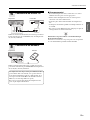
Caution: Disconnect all components from AC outlets before proceeding.
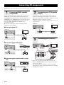
If your TV and DVD player or satellite/cable set-top box have
HDMI jacks, you can connect them via the AV Receiver.
Using HDMI cables (not included), connect the AV Receiver’s
HDMI OUT jack to an HDMI input on your TV, and connect
your DVD player and satellite/cable set-top box to the AV
Receiver’s HDMI 1(BD/DVD) and HDMI 2 jacks,
respectively, as shown.
Refer to the AV Receiver’s owner’s manuals for more
information about
HDMI.
■ Connecting your TV
■ Connecting your DVD player
■ Connecting your satellite/cable set-top
box
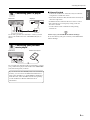
You can listen to TV audio through the AV Receiver and
speakers by connecting an audio output on your TV to an
audio input on the AV Receiver with, for example, an optical
digital audio cable (not included), as shown.
To listen to TV audio, select the appropriate input source on
the AV Receiver.
Use a video pin cable (not included) to connect the AV
Receiver’s MONITOR OUT jack to a composite video input
on your TV, as shown.
Use AV pin cables (not included) to connect your DVR
(digital video recorder) or VCR to the AV Receiver’s AV 5 and
AV OUT jacks, as shown.
Connecting AV components
1
Connecting HDMI-capable
components
ANTENNA
FM
GND
AM
COMPONENT
VIDEO
P
R
P
B
Y
OPTICAL
(
TV
)
AV 1
AV 2
AV 3
AV 4
AV 5
AUDIO 1
AUDIO 2
COAXIAL
(
CD
)
COAXIAL
OPTICAL
VIDEO
CENTER
SURROUND
HDMI 1
(
BD/DVD
)
HDMI 2 HDMI 3
HDMI 4
FRONT
COMPONENT
VIDEO
MONITOR OUT
P
R
P
B
Y
HDMI
OUT
MONITOR OUT
AV
OUT
SUBWOOFER
AUDIO
OUT
SPEAKERS
HDMI
IN
HDMI 1
(
BD/DVD
)
HDMI 2 HDMI 3
HDMI
OUT
AV Receiver TV
ANTENNA
FM
GND
AM
COMPONENT
VIDEO
P
R
P
B
Y
OPTICAL
(
TV
)
AV 1
AV 2
AV 3
AV 4
AV 5
AUDIO 1
AUDIO 2
COAXIAL
(
CD
)
COAXIAL
OPTICAL
VIDEO
CENTER
SURROUND
FRONT
COMPONENT
VIDEO
MONITOR OUT
P
R
P
B
Y
HDMI
OUT
MONITOR OUT
AV
OUT
SUBWOOFER
AUDIO
OUT
SPEAKERS
HDMI 1
(
BD/DVD
)
HDMI 2 HDMI 3
HDMI 4
HDMI
OUT
HDMI 2 HDMI 3
HDMI
OUT
HDMI 1
(
BD/DVD
)
AV Receiver DVD player
ANTENNA
FM
GND
AM
COMPONENT
VIDEO
P
R
P
B
Y
OPTICAL
(
TV
)
AV 1
AV 2
AV 3
AV 4
AV 5
AUDIO 1
AUDIO 2
COAXIAL
(
CD
)
COAXIAL
OPTICAL
VIDEO
CENTER
SURROUND
FRONT
COMPONENT
VIDEO
MONITOR OUT
P
R
P
B
Y
MONITOR OUT
AV
OUT
SUBWOOFER
AUDIO
OUT
SPEAKERS
HDMI
OUT
HDMI 1
(
BD/DVD
)
HDMI 3
HDMI 4
HDMI 2
HDMI
OUT
HDMI 3
HDMI
OUT
HDMI 1
(
BD/DVD
)
HDMI 2
AV Receiver Satellite/cable set-top box
2
Connecting your TV for audio
output
3
Connecting your DVR/VCR
ANTENNA
FM
GND
AM
COMPONENT
VIDEO
P
R
P
B
Y
OPTICAL
(
TV
)
AV
1
AV 2
A
V
3
AV 4
AV 5
AUDIO 1
AUDIO 2
COAXIAL
(
CD
)
COAXIAL
OPTICAL
VIDEO
CENTER
SURROUND
HDMI 1
HDMI 2 HDMI 3
HDMI 4
FRONT
COMPONENT
VIDEO
MONITOR OUT
P
R
P
B
Y
MONITOR OUT
AV
OUT
SUBWOOFER
AUDIO
OUT
SPEAKERS
(
BD/DVD
)
HDMI
OUT
AUDIO OUTPUT
(
TV
)
(
CD
)
COAXIAL
OPTICAL
AV 4AV 3 AV 5
OPTICAL
AV Receiver
TV
MONITOR OUT
ANTENNA
FM
GND
AM
COMPONENT
VIDEO
P
R
P
B
Y
OPTICAL
(
TV
)
AV 1
AV 2
AV 3
AV 4
AV 5
AUDIO 1
AUDIO 2
COAXIAL
(
CD
)
COAXIAL
OPTICAL
VIDEO
CENTER
SURROUND
HDMI 1
HDMI 2 HDMI 3
HDMI 4
FRONT
COMPONENT
VIDEO
MONITOR OUT
P
R
P
B
Y
AV
OUT
SUBWOOFER
AUDIO
OUT
SPEAKERS
(
BD/DVD
)
HDMI
OUT
VIDEO
AUDIO
RR
LL
VIDEO
IN
OUT
(
TV
)
AV 4
AV 5
AUDIO 1
OPTICAL
MONITOR O
AV
OUT
MONITOR OUT
AV Receiver TV
DVR/VCR

Connecting AV components
5 En
English
Use an audio pin cable (not included) to connect your CD
player to the AV Receiver’s AV 3 COAXIAL(CD) jack, as
shown.
Use a 3.5 mm stereo mini plug cable (not included) to connect
your portable music player to the AV Receiver’s PORTABLE
jack (on the front panel), as shown.
■ Almost Finished
• Connect the AV Receiver, subwoofer, and your other AV
components to suitable AC outlets.
• Turn on the AV Receiver first, then the subwoofer and your
other AV components.
• Install the batteries in the AV Receiver’s remote control.
• The optimum crossover frequency setting on the AV
Receiver is 160 Hz.
• See the relevant owner’s manuals for full operating
instructions.
Time to enjoy your Yamaha Home Theater Package!
Now, relax and enjoy the great sound of your Yamaha Home
Theater Package.
4
Connecting your CD player
5
Connecting your portable
music player
SURROUND
ANTENNA
FM
GND
AM
COMPONENT
VIDEO
P
R
P
B
Y
OPTICAL
(
TV
)
A
V 1
AV 2
AV 3
AV 4
AV
5
AUDIO 1
AUDIO 2
COAXIAL
(
CD
)
COAXIAL
OPTICAL
VIDEO
CENTER
SURROUND
HDMI 1
HDMI 2 HDMI 3
HDMI 4
FRONT
COMPONENT
VIDEO
MONITOR OUT
P
R
P
B
Y
MONITOR OUT
AV
OUT
SUBWOOFER
AUDIO
OUT
SPEAKERS
(
BD/DVD
)
HDMI
OUT
(
TV
)
AV 4
OPTICAL
COMPONENT
VIDEO
Y
OPTICAL
AV 1
AV 2
AV 3
AV 5
COAXIAL
(
CD
)
COAXIAL
VIDEO
COAXIAL
AV Receiver CD player
CONTROL
PROGRAM
STRAIGHT
INPUT
VIDEO
AUDIO
PORTABLE
VIDEO
AUX
VOLUME
SCENE
VIDEO
AUDIO
PORTABLE
VIDEO
AUX
AV Receiver Portable music player
If your AV Receiver has a DOCK jack (U.S.A. and Canada
models), you can connect a Yamaha Universal Dock for
iPod, such as the YDS-12, or a Yamaha Bluetooth Wireless
Audio Receiver, such as the YBA-10 (both sold separately).
See the AV Receiver’s Owner’s Manual for more
information.

6 En
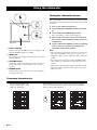
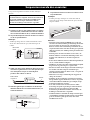
a Power indicator
Lights up when the POWER switch is set to ON; goes off
when the POWER switch is set to OFF.
b INPUT jack
Input jack for connecting the line-level subwoofer output
on your amplifier.
c VOLUME control
Adjusts the volume of the subwoofer. Turn it clockwise to
increase the volume; counterclockwise to decrease the
volume.
d POWER switch
Set this to ON to turn on the subwoofer. Set it to OFF to
turn off the subwoofer.
Setting the subwoofer volume
The very first time you use the subwoofer, you need to set the
volume balance between the subwoofer and the front speakers
as follows.
1 Turn on your other AV components.
2 Set the subwoofer’s VOLUME control to minimum
(0).
3 Set the subwoofer’s POWER switch to ON.
The power indicator on the rear panel lights up.
4 Play an audio source that contains low-frequency
bass sounds. Set the amplifier’s volume control to a
suitable level.
5 Turn the subwoofer’s VOLUME control up gradually
until you achieve a good balance between the
subwoofer and the other speakers.
Notes
• Once the subwoofer volume has been set, you can leave the
subwoofer’s VOLUME control set as it is and use your
amplifier’s volume control to adjust the volume of the entire
system.
• If you replace the front/center speaker (NS-BR300) with
other speakers, you will need to re-adjust the subwoofer’s
volume.
• The frequency characteristics graphs below show how the
subwoofer and front speakers work together to provide a
full-range sound.
Frequency characteristics
Using the subwoofer
4
3
2
1
Rear panel
20 50 100 200 500 Hz
40
50
60
70
80
90
100 dB
NS-SW280
NS-B285
20 50 100 200 500 Hz
40
50
60
70
80
90
100 dB
NS-SW280
NS-BR300
20 50 100 200 500 Hz
40
50
60
70
80
90
100 dB
The following graph shows the
frequency characteristics of the
subwoofer (NS-SW280).
The following graph shows the combined frequency characteristics
of the subwoofer (NS-SW280) and front/center speaker (NS-BR300),
and surround speaker (NS-B285).

7 En
English
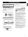
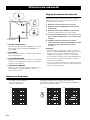
You can mount the speakers on the wall as follows.
• Surround speakers (NS-B285)
1 Install screws into a solid wall or wall support, as
shown below. Use 3.5 to 4 mm (1/8") diameter self-
tapping screws.
2 Hang each speaker by its keyhole slots onto the
protruding screws.
Note
• Make sure the shaft of the screw is seated in the narrow part
of the keyhole slot. Otherwise, the speaker may fall.
• Front/center speaker (NS-BR300)
1 Use tape or thumbtacks to affix the supplied
mounting template to the wall, and use a pencil or
other tool to mark the hole positions on the wall.
2 Remove the template, and then install screws, as
shown below. Use 3.5 to 4 mm (1/8") diameter self-
tapping screws.
3 Hang the speaker by its keyhole slots onto the
protruding screws.
Note
• Make sure the shaft of each screw is seated in the narrow
part of each keyhole slot. Otherwise, the speaker may fall.
Cautions
• The front/center speaker (NS-BR300) weighs 1.5 kg
(3 lbs.). The surround speakers (NS-B285) weigh 0.45 kg
(1 lbs.). Do not mount the speakers on thin plywood or on
walls with a soft surface material. Otherwise, the screws
may pull out of the surface and the speakers may fall,
causing damage or injury.
• Do not affix the speakers to walls by using nails,
adhesives, or unsuitable hardware. Long-term use and
vibration may cause the speakers to fall.
• To prevent tripping accidents, secure loose speaker cables
to walls, floors, etc., using suitable fasteners.
• Mount the speakers at positions on the walls where
people are unlikely to bump their heads.
• Attach the speakers to a rack or wall. Do not attach the
speakers to walls made of weak materials, such as plaster
or veneered woods. Doing so may cause the speakers to
fall.
• Use commercially available screws that can support the
weight of the speakers.
• Only use the screws specified for attaching the speakers.
Using fasteners other than those specified, such as short
screws, nails, or double-sided tape, may cause the
speakers to fall.
• When connecting the speakers, secure the speaker cables
so that they do not hang loose. If your foot or hand
accidentally gets caught on a loose speaker cable, the
speaker may fall, causing damage or injury.
• After installing each speaker, check that it’s fixed securely.
Yamaha accepts no responsibility whatsoever for
accidents due to improper installation.
Wall-mounting the speakers
Unless you are very competent at DIY, do not wall-mount the
speaker yourself. Ask your dealer or a qualified contractor to
do the installation for you. Incorrect installation may cause
the speaker to fall, causing damage or injury.
45 mm
(1-3/4")
Wall/wall
support
6 mm
(1/4")
Minimum
20 mm (3/4")
NS-B285
Tape or
thumbtacks
Mark
here
Mounting
template
4 to 6 mm (3/16" to 1/4")
Diameter:
7 to 9 mm or more (#8,
1/4" to 3/8" or more)

8 En
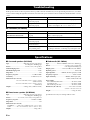
If this product doesn’t work as expected, look for a possible cause below. If the issue you are experiencing is not listed, or you cannot
resolve it after reading through these instructions, disconnect the power cable and contact an authorized Yamaha dealer or service
center.
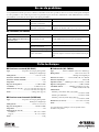
■ Subwoofer (NS-SW280)
■ Surround speakers (NS-B285)
Type ........................................... Full-range acoustic-suspension
non-magnetic shielding type
Driver............................................ 6.5 cm (2-1/2") cone speaker
Nominal input power ......................................................... 30 W
Maximum input power ...................................................... 80 W
Impedance ............................................................................... 6 Ω
Frequency response........................................... 110 Hz–40 kHz
Sensitivity ........................................................81 dB/2.83 V, 1 m
Dimensions (W × H × D)
90 × 90 × 109 mm (3-1/2" × 3-1/2" × 4-1/4")
(without stand)
90 × 120 × 123 mm (3-1/2" × 4-3/4" × 4-7/8")
(with stand)
Wei ght ........................................0.45 kg (1 lbs.) (without stand)
■ Front/center speaker (NS-BR300)
Type ........................................... Full-range acoustic-suspension
non-magnetic shielding type
Driver....................... 4 × 10 cm (1-1/2 × 4 in) cone speaker ×3
Frequency response........................................ 150 Hz to 20 kHz
Impedance ............................................................................... 6 Ω
Dimensions (W × H × D)
NS-BR300 ........... 800 × 50 × 70 mm (31-1/2" × 2" × 2-3/4")
Stand................. 45 × 70 × 88 mm (1-3/4" × 2-3/4" × 3-1/2")
Wei ght ...................................................................... 1.5 kg (3 lbs.)
■ Subwoofer (NS-SW280)
Type
........................ Advanced
Ya m a h a
Active Servo Technology
Driver...............................................16 cm (6-1/2") cone woofer
non-magnetic shielding type
Output power........................ 50 W (100 Hz, 5 Ω, 10% T.H.D.)
Dynamic power ......................................................... 100 W, 5 Ω
Input impedance
....................INPUT (1P RCA pin jack): 10 kΩ
Frequency response .............................................30 Hz–160 Hz
Input sensitivity............................. INPUT (1P RCA pin jack):
80 mV (50 Hz, 50 W/5 Ω)
Power supply
U.S.A. and Canada models...........................AC 120 V, 60 Hz
Australia model..............................................AC 240 V, 50 Hz
U.K. and Europe models...............................AC 230 V, 50 Hz
Dimensions (W × H × D) ........................262 × 264 × 316 mm
(10-3/8" × 10-3/8" × 12-1/2")
Weig ht ................................................................. 6.9 kg (15.2 lbs.)
Specifications are subject to change without notice.
Troubleshooting
Issue Possible cause Remedy
There’s no sound. The speaker cables are not
connected properly.
Make sure the speaker cables are connected properly.
The sound is very quiet. The speaker cables are not
connected properly.
Make sure the speaker cables are connected properly:
L (left) to L, R (right) to R, “+” to “+” and “–” to “–”.
Issue Possible cause Remedy
The POWER switch is set to ON but
the subwoofer doesn’t work.
The power cable is not connected
properly.
Set the POWER switch to OFF, then make sure the power
cable is connected properly.
There’s no sound. The VOLUME control is set to 0. Turn up the VOLUME control.
The subwoofer cable is not
connected properly.
Make sure the subwoofer cable is connected properly.
The subwoofer is too quiet. The source material doesn’t
contain much bass.
Try playing source material that contains more bass.
Bass sounds are being cancelled
out by standing waves.
Reposition the subwoofer, or break up parallel wall surfaces
by placing bookshelves or other large objects along the wall.
Specifications


i Fr
1. Lire ces instructions.
2. Conserver ces instructions.
3. Tenir compte de tous les avertissements.
4. Suivre toutes les instructions.
5. Ne pas utiliser cet appareil à proximité de l’eau.
6. Nettoyer cet appareil avec un chiffon sec seulement.
7. Ne pas recouvrir les ailettes de ventilation. Installer
l’appareil selon les instructions du fabricant.
8. Ne pas installer près d’une source de chaleur, comme un
appareil de chauffage, une résistance électrique, un poêle, ou
tout autre appareil (amplificateurs compris) produisant de la
chaleur.
9. Ne pas désamorcer le système de sécurité d’une fiche
polarisée ou d’une fiche avec mise à la terre. Une fiche
polarisée est munie de deux lames, dont l’une est plus large
que l’autre. Une fiche avec mise à la terre est munie de deux
lames et d’une broche de terre. La lame la plus large ou la
troisième broche sont reliées à la terre pour des raisons de
sécurité. Si la fiche fournie ne s’insère pas dans la prise,
s’adresser à un électricien pour faire remplacer la prise
obsolète.
10. Protéger le cordon d’alimentation de sorte qu’il ne risque pas
d’être piétiné ou coincé, surtout au niveau des fiches, des
prises et de sa sortie de l’appareil.
11. Utiliser seulement les fixations et accessoires spécifiés par le
fabricant.
12. Utiliser seulement le chariot, socle, trépied,
support ou meuble spécifié par le fabricant ou
vendu avec l’appareil. Si un chariot est
utilisé, faire attention de ne pas se blesser ou
de le renverser pendant le transport de
l’appareil
13. Débrancher cet appareil pendant les orages électriques, ou
s’il ne doit pas être utilisé pendant un certain temps.
14. Pour toute inspection s’adresser à un personnel qualifié. Une
inspection est nécessaire en cas de dommage, quel qu’il soit,
par exemple cordon d’alimentation ou fiche endommagé,
liquide répandu ou objet tombé à l’intérieur de l’appareil,
exposition de l’appareil à la pluie ou à l’humidité,
fonctionnement anormal ou chute de l’appareil
.
PRÉCAUTIONS CONCERNANT LA SÉCURITÉ
CAUTION
RISK OF ELECTRIC SHOCK
DO NOT OPEN
ATTENTION : POUR RÉDUIRE LES RISQUES D’INCENDIE ET DE
DÉCHARGE ELECTRIQUE, NE PAS RETIRER LE COUVERCLE
(OU LE PANNEAU ARRIÈRE). AUCUNE PIÈCE INTERNE NE PEUT
ÊTRE CHANGÉE PAR L’UTILISATEUR. POUR L’ENTRETIEN,
S’ADRESSER À UN PERSONNEL QUALIFIÉ.
• Explication des symboles
L’éclair avec une flèche à l’intérieur d’un triangle équi-
latéral est destiné à attirer l’attention de l’utilisateur sur
la présence d’une « tension dangereuse » non isolée à
l’intérieur du produit, pouvant être suffisamment
élevée pour constituer un risque d’électrocution.
Le point d’exclamation à l’intérieur d’un triangle
équilatéral est destiné à attirer l’attention de
l’utilisateur sur la présence d’instructions importantes
sur l’emploi ou de la maintenance (réparation) de
l’appareil dans la documentation fournie.
IMPORTANT
Veuillez enregistrer le numéro de série de cet appareil dans
l’espace réservé à cet effet, ci-dessous.
MODÈLE :
No. de série :
Le numéro de série se trouve à l’arrière de l’appareil. Prière de
conserver le mode d’emploi en lieu sûr pour toute référence
future.
Informations de la FCC (Pour les clients résidents aux États-Unis)
1 AVIS IMPORTANT: NE PAS APPORTER DE
MOFIDICATIONS À CET APPAREIL!
Ce produit est conforme aux exigences de la FCC s’il est
installé selon les instructions du mode d’emploi. Toute
modification non approuvée expressément par Yamaha peut
invalider l’autorisation, accordée par la FCC, d’utiliser ce
produit.
2 IMPORTANT: N’utiliser que des câbles blindés de haute
qualité pour le raccordement de ce produit à des accessoires
et/ou à un autre produit. Seuls le ou les câbles fournis avec le
produit DOIVENT être utilisés. Suivre les instructions
concernant l’installation. Le non respect des instructions peut
invalider l’autorisation, accordée par la FCC, d’utiliser ce
produit aux États-Unis.
3 REMARQUE: Ce produit a été testé et déclaré conforme aux
normes relatives aux appareils numériques de Classe “ B ”,
telles que fixées dans l’Article 15 de la Réglementation FCC.
Ces normes sont destinées à assurer une protection suffisante
contre les interférences nuisibles avec d’autres appareils
électroniques dans une installation résidentielle. Cet
équipement génère et utilise des fréquences radio qui, en cas
d’installation et d’utilisation non conformes aux instructions
du mode d’emploi, peuvent être à l’origine d’interférences
empêchant d’autres appareils de fonctionner.
Cependant, la conformité à la Réglementation FCC ne garantit
pas l’absence d’interférences dans une installation particulière.
Si ce produit devait produire des interférences, ce qui peut être
déterminé en
“ ÉTEIGNANT ” et en “ RALLUMANT ” le produit,
l’utilisateur est invité à essayer de corriger le problème d’une
des manières suivantes:
Réorienter ce produit ou le dispositif affecté par les
interférences.
Utiliser des prises d’alimentation branchées sur différents
circuits (avec interrupteur de circuit ou fusible) ou installer un
ou des filtres pour ligne secteur.
Dans le cas d’interférences radio ou TV, changer de place
l’antenne et la réorienter. Si l’antenne est un conducteur plat de
300 ohms, remplacer ce câble par un câble de type coaxial.
Si ces mesures ne donnent pas les résultats escomptés, prière
de contacter le détaillant local autorisé à commercialiser ce
type de produit. Si ce n’est pas possible, prière de contacter
Yamaha Electronics Corp., États-Unis, 6660 Orangethorpe
Ave, Buena Park, CA 90620.
Les déclarations précédentes NE concernent QUE les produits
commercialisés par Yamaha Corporation of America ou ses
filiales.

ii Fr
Français
Lisez attentivement les précautions d’utilisation suivantes. Yamaha décline toute responsabilité en cas de dommages et/ou de blessures
découlant du non respect de ces consignes.
1. Pour profiter au mieux de votre acquisition, lisez
attentivement ce mode d’emploi. Conservez-le
soigneusement pour référence.
2. Installez les enceintes dans un endroit frais, sec, loin des
fenêtres et des sources de chaleur et de vibration, des
poussières, de l’humidité et du froid. Évitez les sources de
ronflements électriques (transformateurs et moteurs, par
exemple). Pour éviter les risques d’incendie et de secousses
électriques, n’exposez pas les enceintes à la pluie ni à
l’humidité.
3. Pour éviter que la menuiserie des enceintes ne se déforme ou
ne se décolore, n’exposez pas les enceintes à la lumière
directe du soleil ni à une humidité excessive.
4. Évitez d’installer les enceintes dans un endroit exposé à la
chute d’objets ou encore à l’écoulement ou aux
éclaboussures de liquides.
5. Ne posez pas les objets suivants sur le dessus des enceintes:
– D’autres appareils qui pourraient endommager ou
décolorer la menuiserie des enceintes;
– Des objets enflammés (par exemple, des bougies) qui
pourraient endommager les enceintes, provoquer une
blessure, voire un incendie;
– Des récipients contenant des liquides qui pourraient se
renverser, endommager les enceintes ou être à l’origine
d’une secousse électrique.
6. Ne placez pas les enceintes dans un endroit où elles peuvent
être heurtées, directement ou par la chute d’objets. Un
emplacement stable garantit l’obtention de meilleures
sonorités.
7. Placer les enceintes sur des étagères ou dans un meuble qui
contient également la platine de lecture, peut entraîner un
phénomène de bouclage.
8. En cas de “saturation” , réduisez le niveau de sortie de
l’amplificateur. N’excitez pas l’amplificateur au point qu’il
écrête. Dans ce cas en effet, les enceintes pourraient être
endommagées.
9. Vous devez être très attentif, si l’amplificateur peut délivrer
une puissance supérieure à la puissance maximale admissible
par les enceintes, à ce que cela ne se produise pas.
10. Ne nettoyez pas la menuiserie des enceintes avec un produit
chimique qui peut endommager leur finition. Utilisez un
chiffon sec et propre.
11. Ne tentez pas de modifier les enceintes ni de les réparer.
Consultez le service Yamaha compétent si une réparation est
nécessaire. Pour quelque raison que ce soit, ne démontez pas
la menuiserie des enceintes.
12. Prenez connaissance des erreurs fréquentes, mentionnées
dans la section “En cas de problème”, avant de conclure que
les enceintes sont défectueuses.
13. La détermination d’un endroit convenable est de votre
responsabilité. Yamaha ne saurait être responsable des
accidents provoqués par le choix d’un emplacement qui
ne conviendrait pas, ni par l’installation incorrecte des
enceintes.
En ce qui concerne le NS-SW280
1. Ne le faites pas fonctionner à l’envers. Il peut surchauffer et
être endommagé.
2. Manœuvrez les commutateurs et les commandes avec
précaution, veillez aux câbles de liaison. Avant de déplacer
cet appareil, débranchez la fiche du cordon d’alimentation et
les câbles qui le relient aux autres appareils. Ne tirez pas sur
les câbles.
3. N’introduisez jamais votre main ou un objet dans le port
situé sur le côté droit de l’appareil. Lorsque vous déplacez
l’appareil, veillez à ne pas le saisir par ce port; vous risquez
de vous blesser et/ou d’endommager l’appareil.
4. Cet appareil étant doté d’un amplificateur de puissance, il
rayonne de la chaleur, à travers son panneau arrière. Placez
cet appareil loin des murs et ménagez au moins 20 cm au-
dessus, derrière et sur chaque côté pour réduire les risques
d’incendie ou d’endommagement. Par ailleurs, ne
positionnez pas cet appareil de telle manière que son panneau
arrière soit tourné vers le plancher ou en contact avec une
paroi.
5. Si vous utilisez un humidificateur, veillez à réduire les
risques de condensation à l’intérieur de cet appareil en
ménageant suffisamment d’espace libre autour de lui et en
réglant l’humidificateur à une valeur convenable. La
condensation peut provoquer un incendie, endommager
l’appareil et/ou être la cause d’une secousse électrique.
6. Ne couvrez pas le panneau arrière d’un journal, d’une nappe,
d’un rideau, etc., ce qui pourrait empêcher la chaleur de
s’évacuer. Une augmentation anormale de la température
intérieure de l’appareil peut provoquer un incendie,
endommager l’appareil ou entraîner des blessures.
7. Ne branchez pas la fiche du cordon d’alimentation sur une
prise secteur aussi longtemps que tous les raccordements ne
sont pas terminés.
8. La tension à utiliser est indiquée sur le panneau arrière.
Alimenter cet appareil sous une tension supérieure à la
tension prescrite, peut provoquer un incendie, endommager
l’appareil et/ou entraîner des blessures. Yamaha ne saurait
être responsable des dommages résultant de l’utilisation
d’une tension d’alimentation différente de la tension
prescrite.
9. Le son à fréquences très graves produites par cet appareil
peut agir sur la platine de lecture et provoquer un bouclage.
Dans ce cas, éloignez l’appareil de la platine de lecture.
10. Cet appareil peut être endommagé par la production
permanente de certaines fréquences. Par exemple, si un
signal sinusoïdal entre 20 Hz et 50 Hz est produit par un
disque d’essai ou des sons très graves sont générés par un
instrument de musique électronique, etc., ou encore si le
saphir de la platine de lecture frotte sur le microsillon, il sera
bon de réduire le niveau de sortie pour éviter les dommages.
11. Si vous notez que cet appareil produit de la distorsion (par
exemple, des “bruits secs et répétés”, un “martèlement”),
réduisez le niveau de sortie. Les fréquences très graves que
contiennent certaines pistes sonores de film ou certains
passages de musique populaire, peuvent endommager cet
appareil.
Précautions
AVERTISSEMENT
POUR ÉVITER TOUT RISQUE D’INCENDIE OU
D’ÉLECTROCUTION, N’EXPOSEZ PAS CET APPAREIL
À LA PLUIE OU À L’HUMIDITÉ.

iii Fr
Précautions
12. Les vibrations produites par le son à fréquences très graves
peuvent déformer les images affichées sur le téléviseur. Dans
ce cas, éloignez l’appareil du téléviseur.
13. Pour débrancher la fiche du cordon d’alimentation, saisissez
la fiche mais ne tirez pas sur le cordon.
14. Si vous envisagez de ne pas utiliser cet appareil pendant une
longue période (par exemple, pendant des congés),
débranchez la fiche du cordon d’alimentation au niveau de la
prise secteur.
15. Installez l’appareil près de la prise secteur et à un endroit tel que
la fiche secteur soit facilement accessible.
Yamaha et le Groupe des Entreprises Électroniques
Grand Public de l’Association des Industries
Électroniques vous demandent de tirer le meilleur
parti de votre équipement tout en écoutant à un
niveau non dommageable pour l’ouïe, c’est-à-dire
un niveau où vous pouvez obtenir un son fort et
clair, sans hurlement ni distorsion, mais sans aucun danger pour
l’ouïe. Comme les sons trop forts causent des lésions auditives qui
ne peuvent être détectées qu’à long terme, lorsqu’il est trop tard,
Yamaha et le Groupe des Entreprises Électroniques Grand Public
de l’Association des Industries Électroniques vous déconseillent
l’écoute prolongée à des volumes excessifs.
Tant que cet appareil est branché à la prise de courant, il n’est
pas déconnecté du secteur, même s’il est éteint. L’appareil
consomme donc une faible quantité d’électricité.
POUR LES CONSOMMATEURS CANADIENS
Pour éviter les chocs électriques, introduire la lame la plus
large de la fiche dans la borne correspondante de la prise et
pousser jusqu’au fond.
Cet appareil numérique de la classe B est conforme à la norme
NMB-003 du Canada.
Nous vous souhaitons un plaisir
musical durable

1 Fr
Français
Nous vous remercions d’avoir opté pour le Yamaha YHT-494 Pack Numérique Home Cinéma.
Le Yamaha YHT-494 Pack Numérique Home Cinéma offre tout ce qu’il vous faut pour amplifier le son de votre Home Cinéma.
En suivant les instructions de ce manuel, votre installation sera prête en un rien de temps et vous entendrez votre musique et vos
films comme jamais auparavant.
Reportez-vous au mode d’emploi de l’Ampli-tuner AV pour plus de renseignements et pour les précautions à observer pour l’Ampli-
tuner AV.
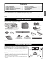
Vérifiez que l’emballage contient les éléments suivants :
Remarque
• Seuls les éléments nécessaires pour terminer l’installation présentée dans ce mode d’emploi sont illustrés.
Avant de raccorder les enceintes, placez chacune d’elles à l’emplacement approprié.
Le positionnement des enceintes est un facteur très important car il influence le son
général du système. Placez donc chaque enceinte à un endroit produisant un son
de qualité optimale à la position d’écoute. Référez-vous à l’illustration.
L’emplacement du subwoofer est moins déterminant que celui des autres
enceintes car les sons très graves ne sont pas très directionnels.
Remarques
• Si des enceintes sont trop près d’un téléviseur à écran cathodique, la couleur de
l’image peut s’en ressentir et cela peut générer un bourdonnement. Dans ce cas,
éloignez les enceintes d’au moins 20 cm du téléviseur. Les téléviseurs à écran
LCD ou plasma ne posent aucun problème.
• Voir page 7 pour de plus amples informations sur l’installation murale des
enceintes.
Contenu de l’emballage
Sommaire
Contenu de l’emballage......................................1
Installation des enceintes...................................1
Connexion des enceintes et des antennes......2
Connexion des éléments AV ..............................4
Utilisation du subwoofer ....................................6
Suspension murale des enceintes.....................7
En cas de problème..............................................8
Fiche technique ....................................................8
VIDEO
AUX
PHONES
SILENT
CINEMA
TONE
CONTROL
STRAIGHT
VOLUME
TV
BD
DVD
CD
RADIO
INPUT
PR
OGRAM
SCENE
VIDEO
AUDIO
PORT
ABLE
LR
INFO
MEMORY
PRESET
FM AM
TUNING
YHT-494
Ampli-tuner AV (HTR-3063)*
* Voir le mode d’emploi de l’Ampli-tuner AV pour une
liste des éléments fournis avec l’Ampli-tuner AV.
Subwoofer (NS-SW280)
Enceintes surround (NS-B285)
Antenne AM Antenne FM
Câble de subwoofer
5 m x1
Câble d’enceinte
25 m x1
Enceinte avant/centrale (NS-BR300)
Gabarit de l’enceinte avant/
centrale (NS-BR300)
Supports et vis de
l’enceinte avant/centrale
(NS-BR300)
Patins antidérapants de
l’enceinte avant/centrale
(NS-BR300)
Mode d’emploi
Supports et vis des enceintes
surround (NS-B285)
Installation des enceintes
Subwoofer
Surround
droite
Surround
gauche
Avant/
centrale

2 Fr
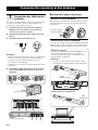
Une fois les enceintes installées, découpez le câble d’enceinte
de 25 m en trois câbles pour raccorder l’enceinte avant/
centrale et les deux enceintes surround.
1 Coupez le câble d’enceinte fourni en segments
adéquats pour les enceintes avant/centrale et
surround. Il vous faut cinq câbles.
2 Dénudez l’extrémité de chaque câble sur environ
10 mm.
3 Torsadez la portion dénudée des fils.
Remarques
• Faites des câbles d’enceinte aussi courts que possible. Evitez
de lier ou d’enrouler la longueur de câble excédentaire.
• Torsadez correctement les fils dénudés pour bien
rassembler les brins individuels.
• Veillez à ne pas vous blesser lors de la préparation des câbles
d’enceinte.
4 Raccordez les câbles d’enceinte à l’enceinte avant/
centrale (NS-BR300) et aux enceintes surround
(NS-B285).
■ Fixation des supports d’enceintes
• Enceintes surround (NS-B285)
Fixez les supports d’enceintes fournis avec les vis lorsque les
enceintes surround sont posées sur une surface plane de la
façon illustrée.
• Enceinte avant/centrale (NS-BR300)
Si vous placez l’enceinte avant/centrale (NS-BR300) à la base du
téléviseur, fixez les supports fournis. Si vous l’utilisez sans les
supports, fixez les patins antidérapants fournis sur l’enceinte.
Connexion des enceintes et des antennes
1
Préparation des câbles et des
enceintes
Bon Mauvais
10 mm
NS-BR300
(enceinte avant/centrale)
NS-B285
(enceintes surround)
Vis pour les supports
d’enceintes NS-B285
Patins
antidérapants
550 mm
695 mm
82 mm
97 mm
Support
Fixation des supports
A l’arrière de l’enceinte avant/centrale (NS-BR300), vous
pouvez remarquer quatre orifices de vis à chaque
extrémité pour fixer les supports à une hauteur et une
largeur adaptées au téléviseur.
Remarque
• Assurez-vous que l’enceinte avant/centrale n’obstrue
pas le détecteur de télécommande à l’avant du téléviseur.
Fixation des patins antidérapants :
Vis des
NS-BR300 supports

Connexion des enceintes et des antennes
3 Fr
Français
Attention : Débranchez tous les éléments des prises secteur avant de poursuivre.
Raccordez les câbles d’enceinte NS-BR300 à l’Ampli-tuner
AV. Veillez à respecter la polarité lorsque vous raccordez
l’enceinte : reliez les bornes positives (+) d’une part et les
bornes négatives (–) d’autre part.
Raccordez les câbles d’enceinte surround à l’Ampli-tuner AV.
Veillez à respecter la polarité lorsque vous raccordez les
enceintes : reliez les bornes positives (+) d’une part et les
bornes négatives (–) d’autre part.
Utilisez le câble de subwoofer fourni pour raccorder la prise
INPUT du subwoofer à la prise SUBWOOFER de l’Ampli-
tuner AV.
Voir la section “Utilisation du subwoofer” à la page 6 pour de
plus amples informations sur le subwoofer et son
fonctionnement.
Raccordez l’antenne cadre AM et l’antenne FM intérieure à
l’Ampli-tuner AV, de la façon illustrée. Reportez-vous au
mode d’emploi de l’Ampli-tuner AV pour en savoir plus sur la
connexion des antennes.
2
Connexion de l’enceinte
avant/centrale (NS-BR300)
3
Connexion des enceintes
surround (NS-B285)
ANTENNA
FM
GND
AM
COMPONENT
VIDEO
P
R
P
B
Y
OPTICAL
(
TV
)
A
V 1
AV 2
AV 3
AV 4
AV 5
AUDIO 1
AUDIO 2
COAXIAL
(
CD
)
COAXIAL
OPTICAL
VIDEO
CENTER
SURROUND
HDMI 1
(
BD/DVD
)
HDMI 2 HDMI 3
HDMI 4
FRONT
COMPONENT
VIDEO
MONITOR OUT
P
R
P
B
Y
HDMI
OUT
MONITOR OUT
AV
OUT
SUBWOOFER
AUDIO
OUT
SPEAKERS
22
33
11
Ampli-tuner AV
Aux bornes R
du NS-BR300
Aux bornes L
du NS-BR300
Aux bornes C
du NS-BR300
ANTENNA
FM
GND
AM
COMPONENT
VIDEO
P
R
P
B
Y
OPTICAL
(
TV
)
AV 1
AV 2
AV 3
AV 4
AV 5
AUDIO 1
AUDIO 2
COAXIAL
(
CD
)
COAXIAL
OPTICAL
VIDEO
CENTER
HDMI 1
(
BD/DVD
)
HDMI 2 HDMI 3
HDMI 4
FRONT
COMPONENT
VIDEO
MONITOR OUT
P
R
P
B
Y
HDMI
OUT
MONITOR OUT
AV
OUT
SUBWOOFER
AUDIO
OUT
SPEAKERS
SURROUND
22
33
11
Ampli-tuner AV
A l’enceinte
surround
droite
A l’enceinte
surround
gauche
4
Connexion du subwoofer
(NS-SW280)
5
Connexion des antennes
ANTENNA
FM
GND
AM
COMPONENT
VIDEO
P
R
P
B
Y
OPTICAL
(
TV
)
AV
1
AV 2
AV
3
A
V 4
AV 5
AUDIO 1
AUDIO 2
COAXIAL
(
CD
)
COAXIAL
OPTICAL
VIDEO
CENTER
SURROUND
HDMI 1
(
BD/DVD
)
HDMI 2 HDMI 3
HDMI 4
FRONT
COMPONENT
VIDEO
MONITOR OUT
P
R
P
B
Y
HDMI
OUT
MONITOR OUT
AV
OUT
SUBWOOFER
AUDIO
OUT
SPEAKERS
SUBWOOFER
Ampli-tuner AV Subwoofer
Câble de
subwoofer
ANTENNA
FM
GND
AM
COMPONENT
VIDEO
P
R
P
B
Y
OPTICAL
(
TV
)
AV 1
AV 2
AV 3
AV 4
AV 5
AUDIO 1
AUDIO 2
COAXIAL
(
CD
)
COAXIAL
OPTICAL
VIDEO
CENTER
SURROUND
HDMI 1
(
BD/DVD
)
HDMI 2 HDMI 3
HDMI 4
FRONT
COMPONENT
VIDEO
MONITOR OUT
P
R
P
B
Y
HDMI
OUT
MONITOR OUT
AV
OUT
SUBWOOFER
AUDIO
OUT
SPEAKERS
ANTENNA
FM
GND
AM
Ampli-tuner AV
Antenne AM
Antenne FM
(Le type d’antenne FM varie selon les
pays.)

4 Fr
Attention : Débranchez tous les éléments des prises secteur avant de poursuivre.
Si le téléviseur, le lecteur DVD ou le décodeur satellite/câble
sont pourvus de prises HDMI, vous pouvez les relier via
l’Ampli-tuner AV. Avec les câbles HDMI (non fournis), reliez
la prise HDMI OUT de l’Ampli-tuner AV à une entrée HDMI
du téléviseur et reliez le lecteur DVD et le décodeur satellite/
câble respectivement aux prises HDMI 1(BD/DVD) et HDMI
2 de l’Ampli-tuner AV, de la façon illustrée.
Reportez-vous au mode d’emploi de l’Ampli-tuner AV pour
de plus amples informations sur l’
HDMI.
■ Connexion du téléviseur
■ Connexion d’un lecteur DVD
■ Connexion d’un décodeur satellite/câble
Vous pouvez écouter le son du téléviseur par l’Ampli-tuner
AV et les enceintes en reliant la sortie audio de votre téléviseur
et l’entrée audio de votre Ampli-tuner AV avec, par exemple,
un câble audio numérique optique (non fourni), de la façon
illustrée.
Pour écouter le son du téléviseur, sélectionnez la source
appropriée sur l’Ampli-tuner AV.
Utilisez un câble vidéo RCA/cinch (non fourni) pour relier la
prise MONITOR OUT de l’Ampli-tuner AV à une entrée
vidéo composite du téléviseur, de la façon illustrée.
Utilisez des câbles AV RCA/cinch (non fournis) pour relier un
enregistreur vidéonumérique ou un magnétoscope aux prises
AV 5 et AV OUT de l’Ampli-tuner AV, de la façon illustrée.
Connexion des éléments AV
1
Connexion d’éléments
compatibles HDMI
ANTENNA
FM
GND
AM
COMPONENT
VIDEO
P
R
P
B
Y
OPTICAL
(
TV
)
AV 1
AV 2
AV 3
AV 4
AV 5
AUDIO 1
AUDIO 2
COAXIAL
(
CD
)
COAXIAL
OPTICAL
VIDEO
CENTER
SURROUND
HDMI 1
(
BD/DVD
)
HDMI 2 HDMI 3
HDMI 4
FRONT
COMPONENT
VIDEO
MONITOR OUT
P
R
P
B
Y
HDMI
OUT
MONITOR OUT
AV
OUT
SUBWOOFER
AUDIO
OUT
SPEAKERS
HDMI
IN
HDMI 1
(
BD/DVD
)
HDMI 2 HDMI 3
HDMI
OUT
Ampli-tuner AV Téléviseur
ANTENNA
FM
GND
AM
COMPONENT
VIDEO
P
R
P
B
Y
OPTICAL
(
TV
)
AV 1
AV 2
AV 3
AV 4
AV 5
AUDIO 1
AUDIO 2
COAXIAL
(
CD
)
COAXIAL
OPTICAL
VIDEO
CENTER
SURROUND
FRONT
COMPONENT
VIDEO
MONITOR OUT
P
R
P
B
Y
HDMI
OUT
MONITOR OUT
AV
OUT
SUBWOOFER
AUDIO
OUT
SPEAKERS
HDMI 1
(
BD/DVD
)
HDMI 2 HDMI 3
HDMI 4
HDMI
OUT
HDMI 2 HDMI 3
HDMI
OUT
HDMI 1
(
BD/DVD
)
Ampli-tuner Lecteur DVD
ANTENNA
FM
GND
AM
COMPONENT
VIDEO
P
R
P
B
Y
OPTICAL
(
TV
)
AV 1
AV 2
AV 3
AV 4
AV 5
AUDIO 1
AUDIO 2
COAXIAL
(
CD
)
COAXIAL
OPTICAL
VIDEO
CENTER
SURROUND
FRONT
COMPONENT
VIDEO
MONITOR OUT
P
R
P
B
Y
MONITOR OUT
AV
OUT
SUBWOOFER
AUDIO
OUT
SPEAKERS
HDMI
OUT
HDMI 1
(
BD/DVD
)
HDMI 3
HDMI 4
HDMI 2
HDMI
OUT
HDMI 3
HDMI
OUT
HDMI 1
(
BD/DVD
)
HDMI 2
Ampli-tuner AV Décodeur satellite/câble
2
Connexion du téléviseur pour
la sortie sonore
3
Connexion d’un enregistreur
vidéo numérique/
magnétoscope
ANTENNA
FM
GND
AM
COMPONENT
VIDEO
P
R
P
B
Y
OPTICAL
(
TV
)
AV 1
AV
2
AV 3
AV
4
AV 5
AUDIO 1
AUDI
O
2
COAXIAL
(
CD
)
COAXIAL
OPTICAL
VIDEO
CENTER
SURROUND
HDMI 1
HDMI 2 HDMI 3
HDMI 4
FRONT
COMPONENT
VIDEO
MONITOR OUT
P
R
P
B
Y
MONITOR OUT
AV
OUT
SUBWOOFER
AUDIO
OUT
SPEAKERS
(
BD/DVD
)
HDMI
OUT
AUDIO OUTPUT
(
TV
)
(
CD
)
COAXIAL
OPTICAL
AV 4AV 3 AV 5
OPTICAL
Ampli-tuner AV
Téléviseur
MONITOR OUT
ANTENNA
FM
GND
AM
COMPONENT
VIDEO
P
R
P
B
Y
OPTICAL
(
TV
)
AV 1
AV 2
AV 3
AV 4
AV 5
AUDIO 1
AUDIO 2
COAXIAL
(
CD
)
COAXIAL
OPTICAL
VIDEO
CENTER
SURROUND
HDMI 1
HDMI 2 HDMI 3
HDMI 4
FRONT
COMPONENT
VIDEO
MONITOR OUT
P
R
P
B
Y
AV
OUT
SUBWOOFER
AUDIO
OUT
SPEAKERS
(
BD/DVD
)
HDMI
OUT
VIDEO
AUDIO
RR
LL
VIDEO
IN
OUT
(
TV
)
AV 4
AV 5
AUDIO 1
OPTICAL
MONITOR O
AV
OUT
MONITOR OUT
Ampli-tuner AV Téléviseur
Enregistreur
La page est en cours de chargement...
La page est en cours de chargement...
La page est en cours de chargement...
La page est en cours de chargement...
-
 1
1
-
 2
2
-
 3
3
-
 4
4
-
 5
5
-
 6
6
-
 7
7
-
 8
8
-
 9
9
-
 10
10
-
 11
11
-
 12
12
-
 13
13
-
 14
14
-
 15
15
-
 16
16
-
 17
17
-
 18
18
-
 19
19
-
 20
20
-
 21
21
-
 22
22
-
 23
23
-
 24
24


Yamaha YHT-494 Le manuel du propriétaire
- Taper
- Le manuel du propriétaire
dans d''autres langues
- English: Yamaha YHT-494 Owner's manual
Documents connexes
-
Yamaha YHT-594 Le manuel du propriétaire
-
-
Yamaha YHT-199 Le manuel du propriétaire
-
-
Yamaha YHT-593 Mode d'emploi
-
-
-
-
-
Yamaha YHT-S400 Le manuel du propriétaire