Metabo WEP15150 Manuel utilisateur
- Catégorie
- Outils électroportatifs
- Taper
- Manuel utilisateur

www.metabo.com Made in Germany
en Operating Instructions 8
fr Mode d'emploi 16
es Instrucciones de manejo 25
W 9-115
W 9-125
W 9-115 Quick
W 9-125 Quick
WP 9-115 Quick
WP 9-125 Quick
WEV 10-125
W 12-125 Quick
W 12-150 Quick
W 12-125 HD
WP 12-115 Quick
WP 12-125 Quick
WP 12-150 Quick
WE 15-125 Quick
WE 15-150 Quick
WE 15-125 HD
WEP 15-125 Quick
WEP 15-150 Quick
WEV 15-125 Quick
WEV 15-150 Quick
WEV 15-125 HT
WEV 15-150 HT
WEV 15-125 Quick Inox
WE 17-125 Quick RT
WEP 17-150 Quick
WEP 17-150 Quick RT

13Y
13X
B
2
2
7 7
A
1
3
2
4
56
7
12
11
13
14
8
910
7
9
8
2

3
15
12
C
0 mm
D
15
(b)
(a)
·ΓʼƑʷÃ̊ƭƖʷƑʼÃ
¸ΓʺƑʷÃ̊ƭƖʷƑʺÃ

4
Metabowerke GmbH, Postfach 1229, Metabo-Allee 1, D-72622 Nuertingen, Germany
W 9-115
W 9-125
W 9-115 Quick
W 9-125 Quick
WP 9-115 Quick
WP 9-125 Quick
WEV 10-125
W 12-125 Quick
W 12-150 Quick
W 12-125 HD
WP 12-115 Quick
WP 12-125 Quick
M-Quick -
- -
✓✓✓✓
-
✓✓
-
✓
✓
Electronic -
------VC-----
Ø in (mm)
4
1
/
2
(115)
5 (125)
4
1
/
2
(115)
5 (125)
4
1
/
2
(115)
5 (125) 5 (125) 5 (125) 6 (150) 5 (125)
4
1
/
2
(115)
5 (125)
t
max1
; t
max2
; t
max3
in (mm)
3
/
8
;
1
/
4
;
1
/
4
(10; 6,8; 6,8)
M / l
- / in
(mm)
5/8“-11 UNC /
13
/
16
(21)
n
min
-1
(rpm)
10500 10500 10500 10500 10500 10500 10500 11000 9600 9600 11000 11000
n
V
min
-1
(rpm)
------
2800-
10500
-----
I
120V
A
8,5 8,5 8,5 8,5 8,5 8,5 9,5 10,5 10,5 10,5 10,5 10,5
m lbs (kg)
4.6 (2,1) 4.6 (2,1) 4.6 (2,1) 4.6 (2,1) 4.6 (2,1) 4.6 (2,1) 4.6 (2,1) 5.3 (2,4) 5.5 (2,5) 5.5 (2,5) 5.3 (2,4) 5.3 (2,4)
a
h,SG
/K
h,SG
m/s
2
4,9/1,5 6,0/1,5 4,9/1,5 6,0/1,5 4,9/1,5 6,0/1,5 6,0/1,5 6,0/1,5 6,8/1,5 5,5/1,5 4,9/1,5 6,0/1,5
a
h,DS
/K
h,DS
m/s
2
<2,5/1,5 <2,5/1,5 <2,5/1,5 <2,5/1,5 <2,5/1,5 <2,5/1,5 <2,5/1,5 <2,5/1,5 3,0/1,5 2,6/1,5 <2,5/1,5 <2,5/1,5
a
h,P
/K
h,P
m/s
2
------------
13.

5
WP 12-150 Quick
WE 15-125 Quick
WE 15-150 Quick
WE 15-125 HD
WEP 15-125 Quick
WEP 15-150 Quick
WEV 15-125 Quick
WEV 15-150 Quick
WEV 15-125 HT
WEV 15-150 HT
WEV 15-125 Quick Inox
WEP 17-150 Quick
WE 17-125 Quick RT
WEP 17-150 Quick RT
M-Quick - ✓✓✓
-
✓✓✓✓
--
✓✓✓✓
Electronic -
- TCTCTCTCTCVTCVTCVTCVTCVTCTCVTCTC
Ø in (mm)
6 (150) 5 (125) 6 (150) 5 (125) 5 (125) 6 (150) 5 (125) 6 (150) 5 (125) 6 (150) 5 (125) 6 (150) 5 (125) 6 (150)
t
max1
; t
max2
; t
max3
in (mm)
3
/
8
;
9
/
32
;
9
/
32
(10; 7,1; 7,1)
M / l
- / in
(mm)
5/8“-11 UNC
/
13
/
16
(21)
n
min
-1
(rpm)
9600 11000 9600 9600 11000 9600 11000 9600 9600 7600 7600 9600 10000 9600
n
V
min
-1
(rpm)
------
2800-
11000
2800-
9600
2800-
9600
2000-
7600
2000-
7600
---
I
120V
A
10,5 13,5 13,5 13,5 13,5 13,5 13,5 13,5 13,5 13,5 13,5 14,5 14,6 14,6
m lbs (kg)
5.5 (2,5) 5.5 (2,5) 5.7 (2,6) 5.7 (2,6) 5.5 (2,5) 5.7 (2,6) 5.5 (2,5) 5.7 (2,6) 5.5 (2,5) 5.7 (2,6) 5.5 (2,5) 5.7 (2,6) 5.5 (2,5) 5.5 (2,5)
a
h,SG
/K
h,SG
m/s
2
6,8/1,5 6,0/1,5 6,8/1,5 5,5/1,5 6,0/1,5 6,8/1,5 6,0/1,5 6,8/1,5 5,0/1,5 4,7/1,5 4,7/1,5 6,8/1,5 6,8/1,5 8,2/1,5
a
h,DS
/K
h,DS
m/s
2
3,0/1,5 3,6/1,5 3,4/1,5 2,6/1,5 3,6/1,5 3,4/1,5 3,6/1,5 3,4/1,5 4,0/1,5 2,5/1,5 2,5/1,5 3,0/1,5 3,0/1,5 4,0/1,5
a
h,P
/K
h,P
m/s
2
--------2,6/1,5<2,5/1,5<2,5/1,5---
13.

(1)(13)(14)
(12)
͌
max
= 180 mm (7“) 6.30383
A
͌
max
= 180 mm (7“) 6.55199
CED 125: 6.26730
CED 125 Plus: 6.26731
GED 125: 6.26732
(12)
C
D
CLICK
͌
max
= 100 mm (4“) 6.30346
͌
max
= 115 mm (4
1
/
2
“) 6.30351
͌
max
= 125 mm (5“) 6.30352
͌
max
= 150 mm (6“) 6.30353
B
(12)
͌
max
= 115 mm (4
1
/
2
“) US339203030
͌
max
= 125 mm (5“) US339203040
͌
max
= 150 mm (6“) US339203050
(1)(13)(14)
GED 125: 6.55153
180 mm / 7“
͌
max
=
100-150 mm / 4“-6“
͌
max
=
(2)
(2)
6

6.30792 (WP 12-..., WEP 15...)
6.30791 (W 12.., WE 15..., WEV 15...)
6.30327
E
F
G
H
6.23262
6.27362
6.30719 (W...RT)
7

ENGLISHen
8
Operating Instructions
The angle grinders, when fitted with original Metabo
accessories, are suitable for grinding, sanding,
abrasive cutting-off operations and wire brushing
metal, concrete, stone and similar materials without
the use of water.
WEV 15-125 HT, WEV 15-150 HT, WEV 15-
125 Quick Inox is additionally suited for light
polishing work. We recommend using our angle
polisher for demanding polishing work in
continuous operation.
Machines with the designation WEV are particularly
suited for working with wire brushes due to
thumbwheel for speed selection.
The user bears sole responsibility for any damage
caused by inappropriate use.
Generally accepted accident prevention
regulations and the enclosed safety information
must be observed.
For your own protection and for the
protection of your electrical tool, pay
attention to all parts of the text that are
marked with this symbol!
WARNING – Reading the operating instruc-
tions will reduce the risk of injury.
Pass on your electrical tool only together with these
documents.
General Power Tool Safety Warnings
WARNING – Read all safety warnings and
instructions. Failure to follow the warnings
and instructions may result in electric shock, fire
and/or serious injury.
Save all warnings and instructions for future
reference! The term "power tool" in the warnings
refers to your mains-operated (corded) power tool
or battery-operated (cordless) power tool.
2.1 Work area safety
a) Keep work area clean and well lit. Cluttered or
dark areas invite accidents.
b) Do not operate power tools in explosive
atmospheres, such as in the presence of
flammable liquids, gases or dust. Power tools
create sparks which may ignite the dust or fumes.
c) Keep children and bystanders away while
operating a power tool. Distractions can cause
you to lose control.
2.2 Electrical safety
a) Power tool plugs must match the outlet.
Never modify the plug in any way. Do not use
any adapter plugs with earthed (grounded)
power tools. Unmodified plugs and matching
outlets will reduce risk of electric shock.
b) Avoid body contact with earthed or
grounded surfaces, such as pipes, radiators,
ranges and refrigerators. There is an increased
risk of electric shock if your body is earthed or
grounded.
c) Do not expose power tools to rain or wet
conditions. Water entering a power tool will
increase the risk of electric shock.
d) Do not abuse the cord. Never use the cord
for carrying, pulling or unplugging the power
tool. Keep cord away from heat, oil, sharp
edges or moving parts. Damaged or entangled
cords increase the risk of electric shock.
e) When operating a power tool outdoors, use
an extension cord suitable for outdoor use.
Use of a cord suitable for outdoor use reduces the
risk of electric shock.
f)
If operating a power tool in a damp location is
unavoidable, use a residual current device
(RCD) protected supply. Use of an RCD reduces
the risk of electric shock.
2.3 Personal safety
a) Stay alert, watch what you are doing and use
common sense when operating a power tool.
Do not use a power tool while you are tired or
under the influence of drugs, alcohol or
medication. A moment of inattention while
operating power tools may result in serious
personal injury.
b) Use personal protective equipment. Always
wear eye protection. Protective equipment such
as dust mask, non-skid safety shoes, hard hat, or
hearing protection used for appropriate conditions
will reduce personal injuries.
c) Prevent unintentional starting. Ensure the
switch is in the off-position before connecting
to power source and/or battery pack, picking
up or carrying the tool. Carrying power tools with
your finger on the switch or energising power tools
that have the switch on invites accidents.
d) Remove any adjusting key or wrench before
turning the power tool on. A wrench or a key left
attached to a rotating part of the power tool may
result in personal injury.
e) Do not overreach. Keep proper footing and
balance at all times. This enables better control of
the power tool in unexpected situations.
f) Dress properly. Do not wear loose clothing or
jewellery. Keep your hair, clothing and gloves
away from moving parts. Loose clothes, jewellery
or long hair can be caught in moving parts.
g) If devices are provided for the connection of
dust extraction and collection facilities, ensure
these are connected and properly used. Use of
dust collection can reduce dust-related hazards.
2.4 Power tool use and care
a) Do not force the power tool. Use the correct
power tool for your application. The correct
1. Specified Use
2. General Safety Instructions

ENGLISH en
9
power tool will do the job better and safer at the rate
for which it was designed.
b) Do not use the power tool if the switch does
not turn it on and off. Any power tool that cannot
be controlled with the switch is dangerous and must
be repaired.
c) Disconnect the plug from the power source
and/or the battery pack from the power tool
before making any adjustments, changing
accessories, or storing power tools. Such
preventive safety measures reduce the risk of
starting the power tool accidentally.
d) Store idle power tools out of the reach of
children and do not allow persons unfamiliar
with the power tool or these instructions to
operate the power tool. Power tools are
dangerous in the hands of untrained users.
e) Maintain power tools. Check for
misalignment or binding of moving parts,
breakage of parts and any other condition that
may affect the power tool's operation. If
damaged, have the power tool repaired before
use. Many accidents are caused by poorly
maintained power tools.
f) Keep cutting tools sharp and clean. Properly
maintained cutting tools with sharp cutting edges
are less likely to bind and are easier to control.
g) Use the power tool, accessories and tool bits
etc. in accordance with these instructions,
taking into account the working conditions and
the work to be performed. Use of the power tool
for operations different from those intended could
result in a hazardous situation.
2.5 Service
a) Have your power tool serviced by a qualified
repair person using only identical replacement
parts. This will ensure that the safety of the power
tool is maintained.
3.1 Safety Warnings Common for Grinding,
Sanding, Wire Brushing or Abrasive
Cutting-Off Operations:
a) This power tool is intended to function as a
grinder, sander, wire brush or cut-off tool. Read
all safety warnings, instructions, illustrations
and specifications provided with this power
tool. Failure to follow all instructions listed below
may result in electric shock, fire and/or serious
injury.WEV 15-125 HT, WEV 15-150 HT, WEV 15-
125 Quick Inox can also be used as polishing tool.
b) Operations such as polishing are not
recommended to be performed with this power
tool. Operations for which the power tool was not
designed may create a hazard and cause personal
injury. (Does not apply to WEV 15-125 HT,
WEV 15-150 HT, WEV 15-125 Quick Inox.)
c) Do not use accessories which are not
specifically designed and recommended by the
tool manufacturer. Just because the accessory
can be attached to your power tool, it does not
assure safe operation.
d) The rated speed of the accessory must be at
least equal to the maximum speed marked on
the power tool. Accessories running faster than
their rated speed can break and fly apart.
e) The outside diameter and the thickness of
your accessory must be within the capacity
rating of your power tool. Incorrectly sized
accessories cannot be adequately guarded or
controlled.
f) Threaded mounting of accessories must
match the grinder spindle thread. For
accessories mounted by flanges, the arbour
hole of the accessory must fit the locating
diameter of the flange. Accessories that do not
match the mounting hardware of the power tool will
run out of balance, vibrate excessively and may
cause loss of control.
g) Do not use a damaged accessory. Before
each use inspect the accessory such as
abrasive wheels for chips and cracks, backing
pad for cracks, tear or excess wear, wire brush
for loose or cracked wires. If a power tool or
accessory is dropped, inspect for damage or
install an undamaged accessory. After
inspecting and installing an accessory,
position yourself and bystanders away from
the plane of the rotating accessory and run the
power tool at maximum no-load speed for one
minute. Damaged accessories will normally break
apart during this test time.
h) Wear personal protective equipment.
Depending on application, use face shield,
safety goggles or safety glasses. As
appropriate, wear dust mask, hearing
protectors, gloves and workshop apron
capable of stopping small abrasive or
workpiece fragments. The eye protection must be
capable of stopping flying debris generated by
various operations. The dust mask or respirator
must be capable of filtering particles generated by
your operation. Prolonged exposure to high
intensity noise may cause hearing loss.
i) Keep bystanders a safe distance away from
work area. Anyone entering the work area must
wear personal protective equipment. Fragments
of workpiece or of a broken accessory may fly away
and cause injury beyond immediate area of
operation.
j) Hold the power tool by insulated gripping
surfaces only, when performing an operation
where the cutting accessory may contact
hidden wiring or its own cord. Cutting accessory
contacting a "live" wire may make exposed metal
parts of the power tool "live" and give the operator
an electric shock.
k) Position the cord clear of the spinning
accessory. If you lose control, the cord may be cut
or snagged and your hand or arm may be pulled into
the spinning accessory.
I) Never lay the power tool down until the
accessory has come to a complete stop. The
3. Special Safety Instructions

ENGLISHen
10
spinning accessory may grab the surface and pull
the power tool out of your control.
m) Do not run the power tool while carrying it at
your side. Accidental contact with the spinning
accessory could snag your clothing, pulling the
accessory into your body.
n) Regularly clean the power tool’s air vents.
The motor’s fan will draw the dust inside the housing
and excessive accumulation of powdered metal
may cause electrical hazards.
o) Do not operate the power tool near
flammable materials. Sparks could ignite these
materials.
p) Do not use accessories that require liquid
coolants. Using water or other liquid coolants may
result in electrocution or shock.
3.2 Kickback and Related Warnings
Kickback is a sudden reaction to a pinched or
snagged rotating wheel, backing pad, brush or any
other accessory. Pinching or snagging causes rapid
stalling of the rotating accessory which in turn
causes the uncontrolled power tool to be forced in
the direction opposite of the accessory’s rotation at
the point of the binding.
For example, if an abrasive wheel is snagged or
pinched by the workpiece, the edge of the wheel
that is entering into the pinch point can dig into the
surface of the material causing the wheel to climb
out or kick out. The wheel may either jump toward or
away from the operator, depending on direction of
the wheel’s movement at the point of pinching.
Abrasive wheels may also break under these
conditions.
Kickback is the result of power tool misuse and/or
incorrect operating procedures or conditions and
can be avoided by taking proper precautions as
given below.
a) Maintain a firm grip on the power tool and
position your body and arm to allow you to
resist kickback forces. Always use auxiliary
handle, if provided, for maximum control over
kickback or torque reaction during start-up.
The operator can control torque reactions or
kickback forces, if proper precautions are taken.
b) Never place your hand near the rotating
accessory. Accessory may kickback over your
hand.
c) Do not position your body in the area where
power tool will move if kickback occurs.
Kickback will propel the tool in direction opposite to
the wheel’s movement at the point of snagging.
d) Use special care when working corners,
sharp edges etc. Avoid bouncing and snagging
the accessory. Corners, sharp edges or bouncing
have a tendency to snag the rotating accessory and
cause loss of control or kickback.
e) Do not attach a saw chain woodcarving
blade or toothed saw blade. Such blades create
frequent kickback and loss of control.
3.3 Safety Warnings Specific for Grinding
and Cutting-Off Operations:
a) Use only wheel types that are recommended
for your power tool and the specific guard
designed for the selected wheel. Wheels for
which the power tool was not designed cannot be
adequately guarded and are unsafe.
b) The grinding surface of centre depressed
discs must be mounted below the plane of the
guard lip. An improperly mounted grinding disc
that projects through the plane of the guard lip
cannot be adequately protected.
c) The guard must be securely attached to the
power tool and positioned for maximum safety,
so the least amount of wheel is exposed
towards the operator. The guard helps to protect
the operator from broken wheel fragments,
accidental contact with wheel and sparks that could
ignite clothing.
d) Wheels must be used only for recommended
applications.
For example: do not grind with the side of cut-
off wheel. Abrasive cut-off wheels are intended for
peripheral grinding, side forces applied to these
wheels may cause them to shatter.
e) Always use undamaged wheel flanges that
are of correct size and shape for your selected
wheel. Proper wheel flanges support the wheel
thus reducing the possibility of wheel breakage.
Flanges for cut-off wheels may be different from
grinding wheel flanges.
f) Do not use worn down wheels from larger
power tools. Wheels intended for larger power
tools are not suitable for the higher speed of a
smaller tool and may burst.
3.4 Additional Safety Warnings Specific for
Abrasive Cutting-Off Operations:
a) Do not “jam” the cut-off wheel or apply
excessive pressure. Do not attempt to make an
excessive depth of cut. Overstressing the wheel
increases the loading and susceptibility to twisting
or binding of the wheel in the cut and the possibility
of kickback or wheel breakage.
b) Do not position your body in line with and
behind the rotating wheel. When the wheel, at the
point of operation, is moving away from your body,
the possible kickback may propel the spinning
wheel and the power tool directly at you.
c) When wheel is binding or when interrupting
a cut for any reason, switch off the power tool
and hold the power tool motionless until the
wheel comes to a complete stop. Never attempt
to remove the cut-off wheel from the cut while
the wheel is in motion otherwise kickback may
occur. Investigate and take corrective action to
eliminate the cause of wheel binding.
d) Do not restart the cutting operation in the
workpiece. Let the wheel reach full speed and
carefully reenter the cut. The wheel may bind,
walk up or kickback if the power tool is restarted in
the workpiece.
e) Support panels or any oversized workpiece
to minimize the risk of wheel pinching and

ENGLISH en
11
kickback. Large workpieces tend to sag under their
own weight. Supports must be placed under the
workpiece near the line of cut and near the edge of
the workpiece on both sides of the wheel.
f) Use extra caution when making a "pocket
cut" into existing walls or other blind areas. The
protruding wheel may cut gas or water pipes,
electrical wiring or objects that can cause kickback.
3.5 Safety Warnings Specific for Sanding
Operations:
a) Do not use excessively oversized sanding
disc paper. Follow manufacturer's
recommendations when selecting sanding
paper. Larger sanding paper extending beyond the
sanding pad presents a laceration hazard and may
cause snagging, tearing of the disc or kickback.
3.6 Only for WEV 15-125 HT, WEV 15-150 HT,
WEV 15-125 Quick Inox: Safety Warnings
Specific for Polishing Operations:
a) Do not allow any loose portion of the
polishing bonnet or its attachment strings to
spin freely. Tuck away or trim any loose
attachment strings. Loose and spinning
attachment strings can entangle your fingers or
snag on the workpiece.
3.7 Safety Warnings Specific for Wire
Brushing Operations:
a) Be aware that wire bristles are thrown by the
brush even during ordinary operation. Do not
overstress the wires by applying excessive
load to the brush. The wire bristles can easily
penetrate light clothing and/or skin.
b) If the use of a guard is recommended for wire
brushing, do not allow any interference of the
wire wheel or brush with the guard. Wire wheel
or brush may expand in diameter due to work load
and centrifugal forces.
3.8 Additional Safety Instructions:
WARNING – Always wear protective
goggles.
Use only accessories that
are covered by at least 3.4
mm by the safety guard.
Use elastic cushioning layers if they have been
supplied with the grinding media and if required.
Observe the specifications of the tool or accessory
manufacturer! Protect the discs from grease or
impacts!
Grinding discs must be stored and handled with
care in accordance with the manufacturer's
instructions.
Never use cutting discs for roughing work! Do not
apply pressure to the side of the cutting discs.
The workpiece must lay flat and be secured against
slipping, e.g. using clamps. Large workpieces must
be sufficiently supported.
If accessories with threaded inserts are used, the
end of the spindle may not touch the base of the
hole on the grinding tool. Make sure that the thread
in the accessory is long enough to accommodate
the full length of the spindle. The thread in the
accessory must match the thread on the spindle.
See page 4-5 and chapter 13. Technical
Specifications for more information on the spindle
length and thread.
Use of a fixed extractor system is recommended.
Always install an RCD with a max. trip current of 30
mA upstream. If the angle grinder is shut down via
the RCD, it must be checked and cleaned. See
chapter 8. Cleaning.
Damaged, eccentric or vibrating tools must not be
used.
Avoid damage to gas or water pipes, electrical
cables and load-bearing walls (static).
Pull the plug out of the socket before making any
adjustments, converting or servicing the machine.
Metabo S-automatic safety clutch. When the safety
clutch responds, switch off the machine
immediately!
A damaged or cracked additional handle must be
replaced. Never operate a machine with a defective
additional handle.
A damaged or cracked safety guard must be
replaced. Never operate a machine with a defective
safety guard.
Secure small workpieces. For example, clamp in a
vice.
Reduce dust exposure:
Particles generated when working with this
machine may contain substances that can
cause cancer, allergic reactions, respiratory
diseases, birth defects or other propagation
defects. Some of these substances include: Lead
(in paint containing lead), mineral dust (from bricks,
concrete etc.), additives used for wood treatment
(chromate, wood preservatives), some wood types
(such as oak or beech dust), metals, asbestos.
The risk depends on for how long the user or nearby
persons are exposed to the substance.
This dust must not be allowed to enter your body.
Do the following to reduce exposure to these
substances: Ensure good ventilation of the
workplace and wear appropriate protective
equipment, such as respirators able to filter
microscopically small particles.
Observe the relevant guidelines for your material,
staff, application and place of application (e.g.
occupational health and safety regulations,
disposal).
Collect the generated particles at the source, avoid
deposits in the surrounding area.
Use suitable accessories for special work (see
chapter 10.), thus less particles enter the
environment in an uncontrolled manner.
Use a suitable extraction unit.
Reduce dust exposure with the following measures:

ENGLISHen
12
- Do not direct the escaping particles and the
exhaust air stream at yourself or nearby persons
or on dust deposits.
- Use an extraction unit and/or air purifiers
- Ensure good ventilation of the workplace and
keep clean using a vacuum cleaner Sweeping or
blowing stirs up dust
- Vacuum or wash the protective clothing Do not
blow, beat or brush
Symbols on the tool:
......... Class II Construction
V............. volts
A............. amperes
Hz........... hertz
W............ watts
Ø ............ max. diameter of the accessory
.../min ..... revolutions per minute
rpm ......... revolutions per minute
~ ............. alternating current
............ alternating current /direct current
n ............. rated speed
The "C" and "US" indicators adjacent to the
CSA Mark signify that the product has been
evaluated to the applicable CSA and ANSI/
UL Standards, for use in Canada and the U.S.,
respectively.
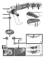
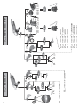
See page 2.
1"Quick"clamping nut *
2 Support flange
3Spindle
4 Spindle locking button
5 Sliding on/off switch *
6Handle
7 Electronic signal indicator *
8 Thumbwheel for selection of speed *
9 Trigger switch *
10 Switch-on lock
11 Additional handle/Additional handle with vibration
damping *
12 Safety cover
13 2-hole nut *
14 2-hole spanner *
15 Lever for safety guard attachment
* depending on equipment/not in scope of delivery
Before plugging in, check to see that the rated
mains voltage and mains frequency, as stated
on the rating label, match with your power supply.
Always install an RCD with a max. trip current
of 30 mA upstream.
5.1 Attaching the additional handle
Always work with the additional handle
attached! (11) Attach the additional handle on
the left or right of the machine and secure.
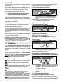
5.2 Attach the safety guard
For safety reasons, always use the safety
guard provided for the respective wheel! See
also chapter10.Accessories!
Safety guard for grinding
Designed for work with roughing wheels, flap
sanding pads, diamond cut-off wheels.
See illustration C on page 2.
- Push and hold the lever. (15) Place the safety
guard in the position indicated. (12)
- Release the lever and turn the safety guard until
the lever engages.
- Push the lever and turn the safety guard until the
closed section is facing the operator.
- Make sure that the guard is placed securely: The
lever must engage and you should not be able to
turn the safety guard.
Use only accessories that
are covered by at least 3.4
mm by the safety guard.
(Disassemble in reverse order.)
Prior to any conversion work: Pull the mains
plug from the socket. The machine must be
switched off and the spindle at a standstill.
For reasons of safety, attach the cutting guard
before performing cutting-off operations (see
chapter 10. Accessories).
6.1 Locking the spindle
- Press in the spindle locking button and turn the
spindle by hand until the spindle locking button
engages. (4) (3)
6.2 Placing the grinding wheel in position
See illustration A on page 2.
- Fit the support flange on the spindle. (2) The
flange should not turn on the spindle when
properly attached.
- Place the grinding disc on the support flange. (2)
The grinding disc must lay flat on the supporting
flange.
6.3 Securing/Releasing the "Quick"
clamping nut (depending on features)
Securing the (1)"Quick" clamping nut:
Only attach the "Quick" clamping nut (1) to
tools with "Metabo Quick System". These
tools can be identified by the red spindle lock button
(4) with "M-Quick" logo
Do not use the "Quick" clamping nut if the
accessory has a clamping shank thicker than
7.1 mm! In this case, use the 2-hole nut (13) with 2-
hole spanner (14).
- Lock the spindle (see chapter 6.1).
4. Overview
5. Commissioning
6. Attaching the grinding disc

ENGLISH en
13
- Position the "Quick" clamping nut on the spindle
so that the 2 lugs engage in the 2 grooves on the
spindle. (1) (3) See illustration on page 2.
- Tighten the "Quick"clamping nut by turning
clockwise by hand.
- Turn the grinding wheel firmly clockwise to tighten
the "Quick"clamping nut.
Releasing the clamping nut (1):
Only when the "Quick" clamping nut (1) is
attached must the spindle be stopped using
the red M-Quick spindle locking button! (4)
- The machine continues to run after switching off.
- Press in the M-Quick spindle locking button just
before the grinding disc stops. (4) The "Quick"
clamping nut (1)loosens itself by around half a turn
and can be removed without additional effort or
tools.
6.4 Securing/Releasing the 2-hole nut
(depending on features)
Securing the 2-hole nut (13):
The 2 sides of the 2-hole nut are different. Screw the
2-hole nut onto the spindle as follows:
See illustration B on page 2.
- X) For thin grinding discs:
The edge of the 2-hole nut (13) faces upwards so
that the thin grinding disc can be attached
securely.
Y) For thick grinding discs:
The edge of the 2-hole nut (13) faces downwards
so that the 2-hole nut can be attached securely to
the spindle.
- Locking the spindle. Turn the 2-hole nut
(13)clockwise using the 2-hole spanner (14) to
secure.
Releasing the 2-hole nut:
- Lock the spindle (see chapter 6.1). Turn the 2-hole
nut (13) anticlockwise using the 2-hole spanner
(14) to unscrew.
7.1 Adjusting the speed (depending on
features)
Set the recommended speed at the thumbwheel.
(8) (small number = low speed; large number = high
speed)
Cutting disc, roughing disc, cup wheel and diamond
cutting disc: high speed
Brush: medium speed
Sanding plate: low to medium speed
Note:
We recommend using our angle polisher for
polishing work.
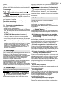
7.2 Switching On and Off
Always guide the machine with both hands.
Switch on first, then guide the accessory
towards the workpiece.
Avoid inadvertent starts: always switch the
tool off when the plug is removed from the
mains socket or if there has been a power cut.
In continuous operation, the machine
continues running if it is forced out of your
hands. Therefore, always hold the machine with
both hands using the handles provided, stand
securely and concentrate.
Avoid the machine swirling up or taking in dust
and chips. After switching off the machine,
only place it down when the motor has come to a
standstill.
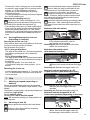
Machines with slide switch:
Switching on: Push the sliding switch forward. (5)
For continuous activation, now tilt
downwards until it engages.
Switching off: Press the rear end of the slide
switch (5) and release it.
Machines with paddle switch
(with dead man function):
Switching on: Slide the switch-on lock (10) in the
direction of the arrow and press the trigger
(9).
Switching off: Release the trigger switch. (9)
Machines with the designation W...RT:
Torque activation (with dead man's lever)
Switching on: Slide the trigger switch (9) forwards
and then push the trigger switch (9)
upwards.
Switching off: Release the trigger switch (9).
Machines with the designation W...RT:
Continuous operation (depending on features)
Switching on: Switch the machine on as described
above. Now slide the trigger switch (9)
forwards again and release in the front
7. Use
0
I
5
0
I
9 10910
0
I
9
0
I
9

ENGLISHen
14
position to lock the trigger switch (9)
(continuous operation).
Switching off: Push the trigger switch (9) upwards
and release.
7.3 Working Directions
Grinding and sanding operations:
Press down the machine evenly on the surface and
move back and forth so that the surface of the
workpiece does not become too hot.
Rough grinding: position the machine at an angle of
30° - 40° for the best working results.
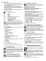
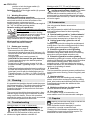
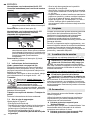
Abrasive cutting-off operations:
Always work against the run of the disc
(see illustration). Otherwise there is
the danger of the machine kicking
back from the cut out of control. Guide
the machine evenly at a speed
suitable for the material being processed. Do not tilt,
apply excessive force or sway from side to side.
Wire brushing / polishing work:
Press down the machine evenly.
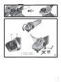
7.4 Rotate gear housing
See illustration D on page 3.
- Disconnect from the power supply.
- Unscrew the fastening screw (a) of the lever (15).
Remove the screw, lever (with its sheet metal part)
and put aside.
- Unscrew the 4 gear housing screws (b).
CAUTION! Do not remove the gear housing!
- Turn the gear housing to the desired position
without removing it.
- Screw in the 4 gear housing screws (b) in the
available threads! Tightening torque = 3.0 Nm +/-
0.3 Nm.
- Slide the spring that pushes the lever in position to
the side and re-insert the lever (15) (with its sheet
metal part), and fix with the fastening screw (a).
Tightening torque = 5.0 Nm +/- 0.5 Nm. Check the
lever for correct function: it has to be under spring
tension.
It is possible that particles deposit inside the power
tool during operation. This impairs the cooling of the
power tool. Conductive build-up can impair the
protective insulation of the power tool and cause
electrical hazards.
The power tool should be cleaned regularly, often
and thoroughly through all front and rear air vents
using a vacuum cleaner. Prior to this operation,
separate the power tool from the power source and
wear protective glasses and dust mask.
Machines with VTC and TC electronics:
The electronic signal display lights up
and the load speed decreases (not
W...RT). (7) There is too much load on the
machine! Run the machine in idling until the
electronics signal indicator switches off.
Machines with VTC, TC and VC electronics:
The electronic signal display (7) flashes
and the machine does not start. The restart
protection is active. If the mains plug is
inserted with the machine switched on, or if the
power supply is restored following an interruption,
the machine does not start up. Switch the machine
off and on again.
Use only genuine Metabo accessories.
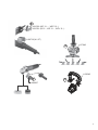
See page 6.
Use only accessories which fulfil the requirements
and specifications listed in these operating
instructions.
A Special safety guard for "hubbed wheels"
For use with "hubbed wheels". The safety guard
must overlap accessories by at least 3.4 mm.
B Cutting guard clip / guard for cut-off
grinding
Designed for work with cutting disc and diamond
cutting discs. Once the cutting guard clip is fitted,
the safety guard becomes a cutting guard.
C Extraction guard for cut-off grinding
Designed for cutting through stone slabs with
diamond cutting discs. With nozzle for extracting
stone dust using a suitable extraction unit.
D Extraction guard for surface grinding
Intended for grinding of concrete, screed, wood and
plastics with diamond cup wheels and/or fibre discs
and suitable sanding plates. With nozzle for
extracting stone, wood and plastic dust using a
suitable extraction unit. Not suitable for extracting
sparks or for grinding of metals.
E Dust filter
The fine mesh filter prevents coarse particles from
entering the motor housing. Remove regularly and
clean.
F Hand protection
Intended for work with backing pads, sanding
plates, wire brushes and support plates, sanding
pads, wire brushes and diamond Drill Bits for tiles.
Install hand guard under the additional side-
mounted handle.
G Multiple position bar for side handle
Permits numerous handle positions.
H Bar side handle
For a complete range of accessories, see
www.metabo.com or the accessories catalogue.
Repairs to electrical tools must be carried out
by qualified electricians ONLY!
If the connection lead is damaged, it must be
replaced by a special connection lead.
Contact your local Metabo representative if you
have Metabo power tools requiring repairs. For
addresses see www.metabo.com.
8. Cleaning
9. Troubleshooting
10. Accessories
11. Repairs

ENGLISH en
15
You can download a list of spare parts from
www.metabo.com.
The generated grinding dust may contain harmful
substances. Dispose appropriately.
Observe national regulations on environmentally
compatible disposal and on the recycling of disused
machines, packaging and accessories.
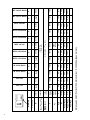
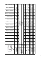
Explanatory notes on the specifications on page 4.
Changes due to technological progress reserved.
Ø = max. diameter of the accessory
t
max,1
= max. permitted thickness of the
clamping shank on accessory when
using 2-hole nut (13)
t
max,2
= max. permitted thickness of clamping
shank on accessory when using
"Quick" clamping nut (1)
t
max,3
= roughing disc/cutting disc:
max. permitted thickness of accessory
M=spindle thread
l = length of the grinding spindle
n* = no-load speed (maximum speed)
n
V
* = no-load speed (adjustable)
I
120 V
= Current at 120 V
m = weight without mains cable
* Machines with the designation WE... : Energy-rich,
high-frequency interference can cause fluctuations
in speed. The fluctuations disappear, however, as
soon as the interference fades away.
The technical specifications quoted are subject to
tolerances (in compliance with the relevant valid
standards).
Emission values
These values make it possible to assess the
emissions from the power tool and to compare
different power tools. Depending on the operating
conditions, the condition of the power tool or the
accessories, the actual load may be higher or lower.
For assessment purposes, please allow for breaks
and periods when the load is lower. Based on the
adjusted estimates, arrange protective measures
for the user e.g. organisational measures.
Vibration total value
(vector sum of three directions)
determined in accordance with EN 60745:
a
h, SG
= Vibration emission value
(surface grinding)
a
h, DS
= Vibration emission value
(sanding with sanding plate)
a
h, P
= Vibration emission value
(polishing)
K
h,SG/DS/P
= Uncertainty (vibration)
Wear ear protectors!
12. Environmental Protection
13. Technical Specifications

FRANÇAISfr
16
Mode d'emploi
Les meuleuses d'angle sont destinées avec les
accessoires Metabo d'origine au meulage, au
ponçage, aux travaux à la brosse métallique et au
tronçonnage de pièces de métal, de béton, de
pierre et d'autres matériaux similaires sans utiliser
d'eau.
Les modèles WEV 15-125 HT, WEV 15-150 HT,
WEV 15-125 Quick Inox conviennent également au
lustrage. Pour les opérations de lustrage
exigeantes en fonctionnement continu, nous
recommandons notre lustreuse d'angle.
Les machines avec la mention WEV conviennent
particulièrement aux travaux avec des brosses
métalliques en raison de leur molette de réglage de
la vitesse.
L'utilisateur sera entièrement responsable de tous
dommages résultant d'une utilisation non conforme
à la destination du chargeur.
Il est impératif de respecter les consignes
générales de protection contre les accidents ainsi
que les consignes de sécurité ci-jointes.
Pour des raisons de sécurité et afin de
protéger l'outil électrique, respecter les
passages de texte marqués de ce
symbole !
AVERTISSEMENT – Lire la notice d'utilisa-
tion afin d'éviter tout risque de blessure.
Remettre l'outil électrique uniquement accompagné
de ces documents.
Avertissements de sécurité généraux pour
l'outil
AVERTISSEMENT – Lire tous les
avertissements de sécurité et toutes les
instructions. Ne pas suivre les avertissements et
instructions peut donner lieu à un choc électrique,
un incendie et/ou une blessure sérieuse.
Conserver tous les avertissements et toutes
les instructions pour pouvoir s'y reporter
ultérieurement! Le terme «outil» dans les
avertissements fait référence à votre outil électrique
alimenté par le secteur (avec cordon d'alimentation)
ou votre outil fonctionnant sur batterie (sans cordon
d'alimentation).
2.1 Sécurité de la zone de travail
a) Conserver la zone de travail propre et bien
éclairée. Les zones en désordre ou sombres sont
propices aux accidents.
b) Ne pas faire fonctionner les outils électri-
ques en atmosphère explosive, par exemple en
présence de liquides inflammables, de gaz ou
de poussières. Les outils électriques produisent
des étincelles qui peuvent enflammer les pous-
sières ou les fumées.
c) Maintenir les enfants et les personnes
présentes à l'écart pendant l'utilisation de
l'outil. Les distractions peuvent vous faire perdre le
contrôle de l'outil.
2.2 Sécurité électrique
a) Il faut que les fiches de l'outil électrique
soient adaptées au socle. Ne jamais modifier la
fiche de quelque façon que ce soit. Ne pas
utiliser d'adaptateurs avec des outils à
branchement de terre. Des fiches non modifiées
et des socles adaptés réduiront le risque de choc
électrique.
b) Eviter tout contact du corps avec des
surfaces reliées à la terre telles que les tuyaux,
les radiateurs, les cuisinières et les
réfrigérateurs. Il existe un risque accru de choc
électrique si votre corps est relié à la terre.
c) Ne pas exposer les outils à la pluie ou à des
conditions humides. La pénétration d'eau à
l'intérieur d'un outil augmentera le risque de choc
électrique.
d) Ne pas maltraiter le cordon. Ne jamais
utiliser le cordon pour porter, tirer ou
débrancher l'outil. Maintenir le cordon à l'écart
de la chaleur, du lubrifiant, des arêtes ou des
parties en mouvement.
Des cordons endom-
magés ou emmêlés augmentent le risque de choc
électrique.
e) Lorsqu'on utilise un outil à l'extérieur,
utiliser un prolongateur adapté à l'utilisation
extérieure. L'utilisation d'un cordon adapté à
l'utilisation extérieure réduit le risque de choc
électrique.
f) Si l'usage d'un outil dans un emplacement
humide est inévitable, utiliser une alimentation
protégée par un dispositif à courant différentiel
résiduel (RCD). L'usage d'un RCD réduit le risque
de choc électrique.
2.3 Sécurité des personnes
a) Rester vigilant, regarder ce que vous êtes en
train de faire et faire preuve de bon sens dans
votre utilisation de l'outil. Ne pas utiliser un
outil lorsque vous êtes fatigué ou sous
l'emprise de drogues, d'alcool ou de médica-
ments. Un moment d'inattention en cours
d'utilisation d'un outil peut entraîner des blessures
graves des personnes.
b) Utiliser un équipement de sécurité. Toujours
porter une protection pour les yeux. Les
équipements de sécurité tels que les masques
contre les poussières, les chaussures de sécurité
antidérapantes, les casques ou les protections
acoustiques utilisés pour les conditions
appropriées réduiront les blessures de personnes.
c) Eviter tout démarrage intempestif. S'assurer
que l'interrupteur est en position arrêt avant de
1. Utilisation conforme à la
destination
2. Consignes générales de
sécurité

FRANÇAIS fr
17
brancher l'outil au secteur et/ou au bloc de
batteries, de le ramasser ou de le porter. Porter
les outils en ayant le doigt sur l'interrupteur ou
brancher des outils dont l'interrupteur est en
position marche est source d'accidents.
d) Retirer toute clé de réglage avant de mettre
l'outil en marche. Une clé laissée fixée sur une
partie tournante de l'outil peut donner lieu à des
blessures de personnes.
e) Ne pas se précipiter. Garder une position et
un équilibre adaptés à tout moment. Cela
permet un meilleur contrôle de l'outil dans des
situations inattendues.
f) S'habiller de manière adaptée. Ne pas porter
de vêtements amples ou de bijoux. Garder les
cheveux, les vêtements et les gants à distance
des parties en mouvement. Des vêtements
amples, des bijoux ou les cheveux longs peuvent
être pris dans des parties en mouvement.
g) Si des dispositifs sont fournis pour le
raccordement d'équipements pour l'extraction
et la récupération des poussières, s'assurer
qu'ils sont connectés et correctement utilisés.
Utiliser des collecteurs de poussière peut réduire
les risques dus aux poussières.
2.4 Utilisation et entretien de l'outil
a) Ne pas forcer l'outil. Utiliser l'outil adapté à
votre application. L'outil adapté réalisera mieux le
travail et de manière plus sûre au régime pour
lequel il a été construit.
b) Ne pas utiliser l'outil si l'interrupteur ne
permet pas de passer de l'état de marche à
arrêt et vice versa. Tout outil qui ne peut pas être
commandé par l'interrupteur est dangereux et il faut
le réparer.
c) Débrancher la fiche de la source
d'alimentation en courant et/ou le bloc de
batteries de l'outil avant tout réglage,
changement d'accessoires ou avant de ranger
l'outil. De telles mesures de sécurité préventives
réduisent le risque de démarrage accidentel de
l'outil.
d) Conserver les outils à l'arrêt hors de la
portée des enfants et ne pas permettre à des
personnes ne connaissant pas l'outil ou les
présentes instructions de le faire fonctionner.
Les outils sont dangereux entre les mains
d'utilisateurs novices.
e) Observer la maintenance de l'outil. Vérifier
qu'il n'y a pas de mauvais alignement ou de
blocage des parties mobiles, des pièces
cassées ou toute autre condition pouvant
affecter le fonctionnement de l'outil. En cas de
dommages, faire réparer l'outil avant de
l'utiliser. De nombreux accidents sont dus à des
outils mal entretenus.
f) Garder affûtés et propres les outils
permettant de couper. Des outils destinés à
couper correctement entretenus avec des pièces
coupantes tranchantes sont moins susceptibles de
bloquer et sont plus faciles à contrôler.
g) Utiliser l'outil, les accessoires et les lames
etc., conformément à ces instructions, en
tenant compte des conditions de travail et du
travail à réaliser. L'utilisation de l'outil pour des
opérations différentes de celles prévues pourrait
donner lieu à des situations dangereuses.
2.5 Maintenance et entretien
a) Faire entretenir l'outil par un réparateur
qualifié utilisant uniquement des pièces de
rechange identiques. Cela assurera que la
sécurité de l'outil est maintenue.
3.1 Avertissements de sécurité communs
pour les opérations de meulage, de
ponçage, de brossage métallique ou de
tronçonnage par meule abrasive :
a) Cet outil électrique est destiné à fonctionner
comme meuleuse, ponceuse, brosse
métallique ou outil à tronçonner. Lire toutes les
mises en garde de
sécurité
, les instructions, les
illustrations et les spécifications fournies avec
cet outil électrique. Le fait de ne pas suivre toutes
les instructions données ci-dessous peut avoir pour
conséquence un choc électrique, un incendie et/ou
une blessure grave.Les modèles WEV 15-125 HT,
WEV 15-150 HT, WEV 15-125 Quick Inox peuvent
également être utilisés comme lustreuses.
b) Les opérations de lustrage ne sont pas
recommandées avec cet outil électrique. Toute
opération non conforme à celles pour lesquelles
l’outil électrique est conçu peut provoquer un
danger et causer un accident corporel. (Non
applicable pour les modèles WEV 15-125 HT,
WEV 15-150 HT, WEV 15-125 Quick Inox.)
c) Ne pas utiliser d’accessoires non conçus
spécifiquement et recommandés par le
fabricant d’outils. Le simple fait que l’accessoire
puisse être fixé à l'outil électrique ne garantit pas un
fonctionnement en toute sécurité.
d) La vitesse assignée de l’accessoire doit être
au moins égale à la vitesse maximale indiquée
sur l’outil électrique. Les accessoires
fonctionnant plus vite que leur vitesse assignée
peuvent se rompre et voler en éclat.
e) Le diamètre extérieur et l’épaisseur de
l'accessoire doivent se situer dans le cadre des
caractéristiques de capacité de l'outil
électrique. Les accessoires dimensionnés de
façon incorrecte ne peuvent pas être protégés ou
commandés de manière appropriée.
f) La taille des meules, flasques, plateaux à
meuler ou tout autre accessoire doit s’adapter
correctement à l’arbre de l’outil électrique. Les
accessoires avec alésages centraux ne
correspondant pas aux éléments de montage de
l’outil électrique seront en déséquilibre, vibreront
excessivement et pourront provoquer une perte de
contrôle.
g) Ne pas utiliser d’accessoire endommagé.
Avant chaque utilisation examiner les
3. Consignes de sécurité
particulières

FRANÇAISfr
18
accessoires comme les meules abrasives pour
détecter la présence éventuelle d'ébréchures
et de fissures, les patins d’appui pour détecter
des traces éventuelles de fissures, de
déchirure ou d’usure excessive, ainsi que les
brosses métalliques pour détecter des fils
desserrés ou fissurés. Si l’outil électrique ou
l’accessoire a subi une chute, examiner les
dommages éventuels ou installer un
accessoire non endommagé. Après examen et
installation d’un accessoire, placer toutes les
personnes présentes à distance du plan de
l’accessoire rotatif et faire marcher l’outil
électrique à vitesse maximale à vide pendant
une minute. Les accessoires endommagés seront
normalement détruits pendant cette période
d’essai.
h) Porter un équipement de protection
individuelle. En fonction de l’application,
utiliser un écran facial, des lunettes de sécurité
ou des verres de sécurité. Le cas échéant,
utiliser un masque antipoussières, des
protections auditives, des gants et un tablier
capables d’arrêter les petits fragments
abrasifs ou des pièces à usiner. La protection
oculaire doit être capable d’arrêter les débris
volants produits par les diverses opérations. Le
masque antipoussières ou le respirateur doit être
capable de filtrer les particules produites par les
travaux. L’exposition prolongée aux bruits de forte
intensité peut provoquer une perte de l’audition.
i) Maintenir les personnes présentes à une
distance de sécurité par rapport à la zone de
travail. Toute personne entrant dans la zone de
travail doit porter un équipement de protection
individuelle. Des fragments de pièce à usiner ou
d’un accessoire cassé peuvent être projetés et
provoquer des blessures en dehors de la zone
immédiate d’opération.
j) Tenir l’outil uniquement par les surfaces de
préhension isolantes, pendant les opérations
au cours desquelles l’accessoire coupant peut
être en contact avec des conducteurs cachés
ou avec son propre câble. Le contact avec un
conducteur électrique sous tension peut également
mettre les parties métalliques de l'outil sous tension
et provoquer un choc électrique.
k) Placer le câble éloigné de l’accessoire de
rotation. En cas de perte de contrôle de l'appareil,
le câble peut être coupé ou accroché et la main ou
le bras de l'utilisateur peuvent être tirés dans
l’accessoire de rotation.
l) Ne jamais reposer l’outil électrique avant
immobilisation complète de l’accessoire.
L’accessoire de rotation peut agripper la surface et
arracher l’outil électrique hors de contrôle.
m) Ne pas faire fonctionner l’outil électrique en
le portant sur le côté. Un contact accidentel avec
l’accessoire de rotation pourrait accrocher les
vêtements et attirer l’accessoire sur l'utilisateur.
n) Nettoyer régulièrement les orifices
d’aération de l’outil électrique. Le ventilateur du
moteur attire la poussière à l’intérieur du boîtier et
une accumulation excessive de poudre de métal
peut provoquer des dangers électriques.
o) Ne pas faire fonctionner l’outil électrique à
proximité de matériaux inflammables. Des
étincelles pourraient enflammer ces matériaux.
p) Ne pas utiliser d’accessoires qui nécessitent
des réfrigérants fluides. L’utilisation d’eau ou
d’autres réfrigérants fluides peut aboutir à une
électrocution ou un choc électrique.
3.2 Rebonds et mises en garde
correspondantes
Le rebond est une réaction soudaine au pincement
ou à l’accrochage d’une meule, d’un patin d’appui,
d’une brosse ou de tout autre accessoire. L'outil
électrique incontrôlable accélère alors dans le sens
opposé de l'accessoire au point d'accrochage.
Par exemple, si une meule est accrochée ou pincée
par la pièce à usiner, le bord de la meule qui entre
dans le point de pincement peut creuser la surface
du matériau, provoquant des sauts ou l’expulsion
de la meule. La meule peut se déplacer en direction
de l’utilisateur ou encore en s’en éloignant, selon le
sens du mouvement de la meule au point de
pincement. Les meules peuvent également se
rompre dans ces conditions.
Le rebond résulte d’un mauvais usage de l’outil et/
ou de procédures ou de conditions de
fonctionnement incorrectes et peut être évité en
prenant les précautions appropriées spécifiées ci-
dessous.
a) Maintenir fermement l’outil électrique et
placer le corps et les bras de manière à pouvoir
résister aux forces de rebond. Toujours utiliser
une poignée auxiliaire, le cas échéant, pour
une maîtrise maximale du rebond ou de la
réaction de couple au cours du démarrage.
L’utilisateur peut maîtriser les couples de réaction
ou les forces de rebond, si les précautions qui
s’imposent sont prises.
b) Ne jamais placer la main à proximité de
l’accessoire en rotation. L’accessoire peut
effectuer un rebond sur la main.
c) Ne pas se placer dans la zone où l’outil
électrique se déplacera en cas de rebond. Le
rebond pousse l’outil dans le sens opposé au
mouvement de la meule au point d’accrochage.
d) Apporter un soin particulier lors de travaux
dans les coins, les arêtes vives etc. Eviter les
rebondissements et les accrochages de
l’accessoire. Les coins, les arêtes vives ou les
rebondissements ont tendance à accrocher
l’accessoire en rotation et à provoquer une perte de
contrôle ou un rebond.
e) Ne pas fixer de lame de scie à chaîne ou de
scie dentée. De telles lames provoquent des
rebonds fréquents et des pertes de contrôle.
3.3 Mises en garde de sécurité spécifiques
aux opérations de meulage et de
tronçonnage abrasif :
a) Utiliser uniquement des types de meules
recommandés pour l'outil électrique et le
protecteur spécifique conçu pour la meule
choisie. Les meules pour lesquelles l’outil
électrique n’a pas été conçu ne peuvent pas être

FRANÇAIS fr
19
protégées de façon satisfaisante et sont
dangereuses.
b) Les meules coudées doivent être fixées de
façon à ce que la surface de rectification se
trouve sous le bord du capot de protection. Une
meule incorrectement fixée, qui dépasse du bord
du capot de protection, ne peut pas être protégée
de façon adaptée.
c) Le capot de protection doit être solidement
fixé à l’outil électrique et réglé à des fins de
sécurité maximale, de sorte que l’opérateur
soit exposé le moins possible à la meule. Le
capot de protection contribue à protéger l'utilisateur
contre les fragments, le contact accidentel avec la
meule, ainsi que contre les étincelles, qui pourraient
enflammer les vêtements.
d) Les meules doivent être utilisées
uniquement pour les applications
recommandées.
Par exemple : ne pas meuler avec le côté de la
meule à tronçonner. Les meules à tronçonner
abrasives sont destinées au meulage périphérique,
l’application de forces latérales à ces meules peut
les briser en éclats. Tout effort latéral sur ces
meules peut les briser.
e) Toujours utiliser des flasques de serrage
non endommagés qui sont de taille et de forme
correctes pour la meule choisie. Des flasques de
meule appropriés supportent la meule réduisant
ainsi la possibilité de rupture de la meule. Les
flasques pour les meules à tronçonner peuvent être
différents des autres flasques de meule.
f) Ne pas utiliser de meules usées d’outils
électriques plus grands. La meule destinée à un
outil électrique plus grand n’est pas appropriée pour
la vitesse plus élevée d’un outil plus petit et elle peut
éclater.
3.4 Mises en garde de sécurité
additionnelles spécifiques aux
opérations de tronçonnage abrasif :
a) Ne pas «coincer» la meule à tronçonner ou
ne pas appliquer une pression excessive. Ne
pas tenter d’exécuter une profondeur de coupe
excessive. Une contrainte excessive de la meule
augmente la charge et la probabilité de torsion ou
de blocage de la meule dans la coupe et la
possibilité de rebond ou de rupture de la meule.
b) Ne pas se placer dans l’alignement de la
meule en rotation ni derrière celle-ci. Lorsque la
meule, au point de fonctionnement, s’éloigne du
corps, le rebond éventuel peut propulser la meule
en rotation et l’outil électrique directement sur
l'utilisateur.
c) Lorsque la meule se bloque ou lorsque la
coupe est interrompue pour une raison
quelconque, mettre l’outil électrique hors
tension et tenir l’outil électrique immobile
jusqu’à ce que la meule soit à l’arrêt complet.
Ne jamais tenter d’enlever la meule à
tronçonner de la coupe tandis que la meule est
en mouvement sinon le rebond peut se
produire. Rechercher et prendre des mesures
correctives afin d’empêcher que la meule ne se
grippe.
d) Ne pas reprendre l’opération de coupe dans
la pièce à usiner. Laisser la meule atteindre sa
pleine vitesse et rentrer avec précaution dans
le tronçon. La meule peut se coincer, venir
chevaucher la pièce à usiner ou effectuer un rebond
si l’on fait redémarrer l’outil électrique dans la pièce
à usiner.
e) Prévoir un support de panneaux ou de toute
pièce à usiner surdimensionnée pour réduire le
risque de pincement et de rebond de la meule.
Les grandes pièces à usiner ont tendance à fléchir
sous leur propre poids. Les supports doivent être
placés sous la pièce à usiner près de la ligne de
coupe et près du bord de la pièce des deux côtés de
la meule.
f) Être particulièrement prudent lors d'une
« coupe en retrait » dans des parois existantes
ou dans d’autres zones sans visibilité. La meule
saillante peut couper des tuyaux de gaz ou d’eau,
des câblages électriques ou des objets, ce qui peut
entraîner des rebonds.
3.5 Mises en garde de sécurité spécifiques
aux opérations de ponçage :
a) Ne pas utiliser de papier abrasif trop
surdimensionné pour les disques de ponçage.
Suivre les recommandations des fabricants
lors du choix du papier abrasif. Un papier abrasif
plus grand s’étendant au-delà du patin de ponçage
présente un danger de lacération et peut provoquer
un accrochage, une déchirure du disque ou un
rebond.
3.6 Uniquement pour les modèles
WEV 15-125 HT, WEV 15-150 HT,
WEV 15-125 Quick Inox : Mises en garde
de sécurité spécifiques aux opérations
de lustrage :
Ne laisser aucune pièce détachée du bonnet de
polissage, particulièrement les cordons
d'attache. Ranger ou couper les cordons
d'attache. Les cordons d'attache lâches, entraînés
dans une rotation peuvent attraper les doigts ou se
coincer dans une pièce à usiner.
3.7 Mises en garde de sécurité spécifiques
aux opérations de brossage métallique :
a) Garder à l’esprit que des brins métalliques
sont rejetés par la brosse même au cours d’une
opération ordinaire. Ne pas soumettre à une
trop grande contrainte les fils métalliques en
appliquant une charge excessive à la brosse.
Les brins métalliques peuvent aisément pénétrer
dans des vêtements légers et/ou la peau.
b) Si l’utilisation d’un protecteur est
recommandée pour le brossage métallique, ne
permettre aucune gêne du touret ou de la
brosse métallique au protecteur. Le touret ou la
brosse métallique peut se dilater en diamètre en
raison de la charge de travail et des forces
centrifuges.

FRANÇAISfr
20
3.8 Autres consignes de sécurité :
AVERTISSEMENT – Portez toujours des
lunettes de protection.
Utiliser exclusivement des
outils accessoires, qui sont
au minimum en retrait de
3,4 mm par rapport au capot
de protection.
Utiliser des intercalaires souples s'ils ont été fournis
avec l'accessoire de meulage et que leur utilisation
s'impose.
Respectez les indications de l'outil ou du fabrication
d'accessoires ! Protéger les disques des graisses
et des coups !
Les meules doivent être conservées et manipulées
avec soin, conformément aux instructions du
fabricant.
Ne jamais utiliser de meule à tronçonner pour les
travaux de dégrossissage ! Ne pas appliquer de
pression latérale sur les meules à tronçonner.
La pièce à usiner doit être fermement fixée de sorte
à ne pas glisser, par exemple à l'aide de dispositifs
de serrage. Les pièces à usiner de grande taille
doivent être suffisamment soutenues.
Si les outils de travail sont utilisés avec un insert
fileté, l'extrémité de la broche ne doit pas toucher le
fond perforé de l'outil de meulage. S'assurer que le
filetage de l'accessoire soit suffisamment long pour
accueillir la broche dans sa longueur. Le filetage de
l'accessoire doit s'adapter au filetage de la broche.
Voir la longueur et le filetage de la broche aux
pages 4-5 et au chapitre 13. Caractéristiques
techniques.
Il est recommandé d'utiliser un système d'aspiration
en poste fixe. Montez toujours un interrupteur de
protection contre les courants de court-circuit
(RCD) avec un courant de déclenchement max. de
30 mA en amont. Lorsque la ponceuse d'angle est
arrêtée par son interrupteur de protection FI, elle
doit être vérifiée et nettoyée. Voir chapitre 8.
Nettoyage.
Ne jamais utiliser d'élément endommagé,
présentant des faux-ronds ou vibrations.
Éviter les dommages sur les conduites de gaz ou
d'eau, les câbles électriques et les murs porteurs
(statiques).
Débrancher le cordon d'alimentation de la prise de
courant avant toute opération de réglage, de
changement d'outil de travail ou de maintenance.
Débrayage de sécurité Metabo S-automatic. En cas
de déclenchement du débrayage de sécurité,
arrêtez immédiatement la machine !
Une poignée supplémentaire endommagée ou
craquelée doit être remplacée. Ne pas utiliser la
machine si la poignée supplémentaire est
défectueuse.
Un capot de protection endommagé ou craquelé
doit être remplacé. Ne pas utiliser la machine si le
capot de protection est défectueux.
Les pièces de petite taille doivent être serrées, par
ex. en les serrant dans un étau.
Réduction de la pollution due aux poussières :
Les particules émises lors du travail avec cette
machine peuvent contenir des substances
pouvant entraîner des cancer, des réactions
allergiques, des affections des voies respiratoires,
des malformations congénitales ou d'autres lésions
du système reproducteur. Parmi ces substances on
trouve : Le plomb (dans les enduits contenant du
plomb), la poussière minérale (dans les briques, le
béton, etc.), les additifs pour le traitement du bois
(chromate, produits de protection du bois),
quelques variétés de bois (comme la poussière de
chêne et de hêtre), les métaux, l'amiante.
Le risque dépend de la durée et de la proximité
d'exposition de l'utilisateur.
Il est souhaitable que le corps n'absorbe pas ces
particules.
Afin de réduire la pollution due à ces substances :
Veillez à une bonne aération du lieu de travail et
portez un équipement de protection adapté comme
par exemple des masques antipoussières capables
de filtre les particules microscopiques.
Respectez les directives applicables au matériau,
au personnel, à l'application et au lieu d'utilisation
(par exemple directives en matière de protection au
travail, élimination des déchets).
Collectez les particules émises sur le lieu
d'émission et évitez les dépôts dans
l'environnement.
Utilisez des accessoires adaptés pour les travaux
spécifiques (voir chapitre 10.). Cela permet de
réduire l'émission incontrôlée de particules dans
l'environnement.
Utilisez un système d'aspiration des poussières
adapté.
Réduisez la pollution due aux poussières en :
- évitant d'orienter les particules sortantes et l'air
d'échappement de la machine vers vous ou vers
des personnes se trouvant à proximité ou vers des
dépôts de poussière,
- utilisant un système d'aspiration et/ou un
purificateur d'air,
- aérant convenablement le lieu de travail et en
l'aspirant pour le maintenir propre. Balayer ou
souffler les poussières les font tourbillonner.
- Aspirez ou lavez les vêtements de protection. Ne
pas les souffler, les battre ni les brosser.
Symboles sur l'outil:
..........Construction de classe II
V..............volts
A..............ampères
Hz............hertz
W.............watts
Ø .............diamètre max. de l'outil de travail
.../min ......révolutions par minute
rpm..........révolutions par minute
~..............courant alternatif
.............courant alternatif / courant continu
n ..............vitesse à vide
Les mentions "C" et "US" ajoutées au label
CSA signifient qu'il s'agit d'un produit
conforme aux normes CSA et ANSI/UL,
applicables pour un emploi du produit respective-
ment au Canada et aux Etats-Unis.
La page charge ...
La page charge ...
La page charge ...
La page charge ...
La page charge ...
La page charge ...
La page charge ...
La page charge ...
La page charge ...
La page charge ...
La page charge ...
La page charge ...
La page charge ...
La page charge ...
La page charge ...
La page charge ...
-
 1
1
-
 2
2
-
 3
3
-
 4
4
-
 5
5
-
 6
6
-
 7
7
-
 8
8
-
 9
9
-
 10
10
-
 11
11
-
 12
12
-
 13
13
-
 14
14
-
 15
15
-
 16
16
-
 17
17
-
 18
18
-
 19
19
-
 20
20
-
 21
21
-
 22
22
-
 23
23
-
 24
24
-
 25
25
-
 26
26
-
 27
27
-
 28
28
-
 29
29
-
 30
30
-
 31
31
-
 32
32
-
 33
33
-
 34
34
-
 35
35
-
 36
36


Metabo WEP15150 Manuel utilisateur
- Catégorie
- Outils électroportatifs
- Taper
- Manuel utilisateur
dans d''autres langues
- English: Metabo WEP15150 User manual
- español: Metabo WEP15150 Manual de usuario
Documents connexes
-
Metabo WP 13-150 Quick RT Mode d'emploi
-
-
-
-
-
Metabo PE 15-30 Manuel utilisateur
-
-
-
-