La page est en cours de chargement...

Manual No.: 15327001
Date of Release 04.04.2011
Labotom-3
Instruction Manual

Labotom-3
Instruction Manual
Table of Contents Page
User’s Guide ............................................................... 1
Reference Guide ....................................................... 15
Quick Reference ....................................................... 27
Always state Serial No and Voltage/frequency if you have technical questions or when ordering spare parts.
You will find the Serial No. and Voltage on the type plate of the machine itself. We may also need the Date
and Article No of the manual. This information is found on the front cover.
The following restrictions should be observed, as violation of the restrictions may cause cancellation of
Struers legal obligations:
Instruction Manuals: Struers Instruction Manual may only be used in connection with Struers equipment
covered by the Instruction Manual.
Service Manuals: Struers Service Manual may only be used by a trained technician authorised by Struers.
The Service Manual may only be used in connection with Struers equipment covered by the Service Manual.
Struers assumes no responsibility for errors in the manual text/illustrations. The information in this manual is
subject to changes without notice. The manual may mention accesso
ries or parts not included in the present
version of the equipment.
Original instructions. The contents of this manual is the property of Struers. Reproduction of any part of this
manual without the written permission of Struers is not allowed.
All rights reserved. © Struers 2011.
Struers A/S
Pederstrupvej 84
DK-2750 Ballerup
Denmark
Telephone +45 44 600 800
Fax +45 44 600 801

Labotom-3
Instruction Manual
Labotom-3
Safety Precaution Sheet
To be read carefully
before use
1. The operator(s) should be fully instructed in the use of the machine and
its cut-off wheels according to the Instruction Manual and the
instructions for the cut-off wheels.
2. The machine must be placed on a safe and stable support table. All the
machines safety functions and guards must be in working order.
3. Use only intact cut-off wheels. The cut-off wheels must be approved for
min. 50 m/s.
4. Observe the current safety regulations for handling, mixing, filling,
emptying and disposal of the additive for cooling fluid.
5. The workpiece must be securely fixed in the quick-clamping device or
the like. Large or sharp workpieces must be handled in a safe way.
6. Protruding workpieces should be shielded or marked.
7. The cutting handle should be lowered slowly and carefully, in order to
avoid breaking the cut-off wheel.
8. Struers recommends the use of an exhaust system as the materials to
be cut may emit harmful gasses or dust.
9. Do not open the protection guard before the cut-off wheel has stopped
completely.
10. Do not put your hands through the rubber curtain during operation of
the machine.
The equipment should only be used for its intended purpose and as detailed in the Instruction Manual.
The equipment is designed for use with consumables supplied by Struers. If subjected to misuse, improper
installation, alteration, neglect, accident or improper repair, Struers will accept no responsibility for
damage(s) to the user or the equipment.
Dismantling of any part of the equipment, during service or repair, should always be performed by a qualified
technician (electromechanical, electronic, mechanical, pneumatic, etc.).


Labotom-3
Instruction Manual
1
User’s Guide
Table of Contents Page
1.Getting Started
Checking the Contents of the Crate ................................................... 2
Unpacking Labotom-3 ........................................................................ 2
Placing Labotom-3 ............................................................................. 2
Getting Acquainted with Labotom-3 ................................................... 3
Cooling Valve ............................................................................ 4
Back view .................................................................................. 5
Noise Level ........................................................................................ 6
Supplying Power ................................................................................ 6
Direction of the Cut-off Wheel ................................................... 6
Connecting a Cooli-1/-3/-5 Cooling Unit ............................................. 7
Mounting the Quick-Clamping Device and Spring Clamp .................. 8
2.Basic Operations
Using the Controls .............................................................................. 9
Front Panel Controls of Labotom-3 .......................................... 9
Controls ............................................................................................ 10
Mounting a Cut-off Wheel ................................................................ 11
Dismounting a Cut-off Wheel ........................................................... 11
Clamping the Workpiece .................................................................. 12
Starting/Stopping the Cutting Process ............................................. 13
3.Regular Maintenance
Recirculation Cooling Unit ....................................................... 14
Daily ................................................................................................. 14
Weekly ............................................................................................. 14

Labotom-3
Instruction Manual
2
1. Getting Started
In the packing crate you should find the following parts:
1 Fork spanner 24mm, for changing the cut-off wheel
1 Inlet hose, 13mm dia., 2m
1 Outlet hose, 50mm dia., 2m
4 Hose clamps
1 Elbow pipe, 90°
1 Elbow pipe, 45°
1 Drain pipe
1 Set of Instruction Manuals
Use a 13 mm socket spanner to remove the screws underneath
the pallet.
Labotom-3 should be placed on an optional Struers table unit, or
other suitable table. Ensure that the table is level.
The table should be able to carry a weight of min. 100 kg. The depth
should be at least 750 mm. Generally, the best working position will
be achieved using a table 800 mm high or lower.
Make sure there is enough room behind the table for the inlet and
outlet hoses and for the protection guard to be opened fully.
Checking the Contents
of the Crate
Unpacking Labotom-3
Placing Labotom-3
Note: Placing Labotom-3 on a table unit
Lead the electric cable, inlet and outlet hose through the opening
in the back of the table.

Labotom-3
Instruction Manual
3
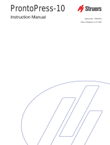
Take a moment to familiarise yourself with the location and names of
the Labotom-3 components.
Front panel controls
Lifting handle for protection guard
Protection guard
Cutting handle
Opening for protruding workpieces
Main power switch
Getting Acquainted
with Labotom-3

Labotom-3
Instruction Manual
4
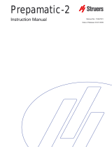
Spindle lock
Tilting cutting unit
Connection for external fume
extraction system (optional kit required)
Cut-off wheel
Cutting table
Quick-clamping device (optional)
Spring clamp (optional)
The cooling valve lever is mounted behind the guard for the cut-off
wheel.
Cutting the lever is turned clockwise and the water is directed
to cool the cut-off wheel.
Cleaning the lever is turned counter-clockwise to flush the
cutting chamber.
Cooling Valve
Lever

Labotom-3
Instruction Manual
5
Electrical cable for power supply
Back plate
Name plate
Flush hose
Water outlet
Water inlet
Cooli Unit connection
Back view

Labotom-3
Instruction Manual
6
Approx. 64 dB (A) measured at idle running, at a distance of
1.0 m/39.4” from the machine.
Labotom-3 is factory mounted with an electric cable. Mount a
plug on the cable:
Black and brown: phase
Yellow/green: earth
Check that the cut-off wheel rotates in the direction indicated by the
arrow on the guard for the cut-off wheel. If the direction of rotation is
incorrect, switch two of the phases.
Noise Level
Supplying Power
IMPORTANT
Check that the mains voltage corresponds to the voltage stated on the type
plate on the back of the machine.
Direction of the Cut-off Wheel

Labotom-3
Instruction Manual
7
To ensure optimal cooling, Labotom-3 can be fitted with a Cooli unit.
Cooling System 3 is a Cooli configuration designed for use with
Labotom.
To connect the Labotom-3 to a Cooli unit:
Plug the Cooli-1/-3/-5 control unit’s communication cable into the
Labotom’s control socket.
Connect the Cooli water inlet hose to the Cooli pump using the
quick coupling (A).
Connect the other end of the hose to the quick coupling of the
Labotom water inlet.
Insert the drain pipe in the water outlet on the back of Labotom-
3 and mount the 90° elbow pipe . Lubricate the sealing ring with
grease or soap to facilitate insertion. (Use the other elbow pipe if
more suitable).
Strip the steel spring from approx. 3 cm of the outlet hose and cut.
Bend the cut end towards the centre of the hose. Mount the outlet
hose onto the elbow pipe and clamp the stripped section using
a hose clamp.
Check that the outlet hose slopes downwards when connected. If
necessary adjust the length of the hose.
Insert the open end of the hose into mounting hole in the bracket
on top of the Cooli filter unit (B).
Connect the cooling unit to the mains power supply.
Connecting a Cooli-1/-3/-5
Cooling Unit
Note
Before connecting the cooling unit to the Labotom, follow the instructions in
the Cooli-1/-3/-5 Instruction Manual to prepare it for use.
IMPORTANT
Before connecting, check that the mains voltage corresponds to the voltage
stated on the type plate on the side of the machine.
A
B

Labotom-3
Instruction Manual
8
The quick clamping device and spring clamp are ordered separately.
Mount the back stop for the quick clamping device on the left
hand side of the cutting table. The cut out corner should be on
the right. Do not tighten the screws.
Mount the back stop for the spring clamp on the right hand side
of the cutting table, with the flat surface facing the front. Do not
tighten the screws.
Place the back stops as needed. The usual position is at the
back of the cutting table parallel to the front. (Use a ruler).
Tighten the screws using the socket spanner.
Mount the quick clamping device on the left hand side of the
cutting table and the spring clamp on the right. Their positions
can be adjusted for the dimensions of the workpiece. Tighten the
screws using the socket spanner.
Mounting the Quick-Clamping
Device and Spring Clamp
Quick clamping device
Spring clamp

Labotom-3
Instruction Manual
9
2. Basic Operations
Please see drawing 1 in the Section Getting Acquainted with
Labotom-3.
Please see drawing 2 in the Section Getting Acquainted with
Labotom-3.
Using the Controls
Front Panel Controls of
Labotom-3
Location of the Main
Switch
Location of the Flush Hose

Labotom-3
Instruction Manual
10
Name Key Function
Name Key Function
MAIN
SWITCH
The main switch is located on
the right hand side of Labotom-3.
Turn clockwise to switch on the
power.
The main switch also serves as
an emergency stop.
FLUSH
Starts the pump for flushing.
The flush nozzle is located in the
rear of the cutting chamber, to
the right.
The flushing hose can be pulled
out and pushed back.
Press nozzle to flush.
START
Starts the machine. The cut-off
wheel starts rotating and the
cooling water is turned on.
Cannot be activated with the
protection guard open or
overload of the cutting motor.
STOP
Stops the machine. The cut-off
wheel stops rotating and the
cooling water is turned off.
Stops the flushing, when
activated.
Controls

Labotom-3
Instruction Manual
11
Put the rim into the groove in the top of the guard for the cut-off
wheel and slot the cut-off wheel into position.
Mount the flange, washer and nut.
Press the knob for the spindle lock on the right-hand side of the
cut-off wheel, turning the cut-off wheel until the spindle lock
clicks.
Tighten the nut moderately with the fork spanner and release the
spindle lock.
Note: The spindle on Labotom-3 is left-hand threaded.
Push the cutting handle backwards to place the tilting cutting unit
in the back position.
Press the knob for the spindle lock on the right-hand side of the
cut-off wheel, turning the cut-off wheel until the spindle lock
clicks.
Remove the nut with the fork spanner. Remove the washer,
flange and old cut-off wheel.
Note: The spindle on Labotom-3 is left-hand threaded.
Mounting a Cut-off Wheel
Nut
Washer
Flange
IMPORTANT
Conventional cut-off wheels like Al2O3
For maximum precision with diamond or CBN cut-off wheels, do not use
cardboard discs.
/SiC should be placed between two
cardboard discs, to protect the cut-off wheel.
Dismounting a Cut-off Wheel

Labotom-3
Instruction Manual
12
The following covers the use of the quick-clamping device and spring
clamp, which can be ordered separately.
Clean the cutting table with the flush hose.
Place the workpiece between the clamp in the quick-clamping
device and the back stop on the left hand side of the cutting
table.
Adjust the position of the clamps, if needed. Use the socket
spanner.
Pull the handle for the spring clamp and place the workpiece in
the desired position for the cut. Lower the cut-off wheel to check
the position.
Turn the handle on the quick-clamping device to vertical position.
Push the clamp device towards the workpiece and lock it firmly
by pulling the locking handle back.
Clamping the Workpiece
IMPORTANT
It is very important that the workpiece is firmly and securely fixed in the
quick-clamping device.
Note: Placing the Back Stop
Generally the back stop should be placed at the rear of the cutting table in
order to leave maximum room for the workpiece.
When cutting ductile materials like aluminium, a smoother cutting action can
be achieved by placing the workpiece further to the front of the machine.

Labotom-3
Instruction Manual
13
The protection guard is fitted with a hydraulic brake action.
Carefully close the protection guard, release and allow to close
automatically.
Switch on the main power.
Press the START
Carefully move the cut-off wheel towards the workpiece by
pulling the cutting handle until it is in contact with the workpiece.
button to start the machine. The cut-off
wheel starts rotating and the cooling water is turned on (check
that the cooling valve lever is in cutting position -lever
horizontal).
Let the cut-off wheel make a small notch in the workpiece. Then
increase the force and continue cutting. Adapt the speed at
which the cut-off wheel is fed through the workpiece to suit the
material and the wheel.
When the cut-off wheel has almost cut through the workpiece,
reduce the cutting force.
Return the cutting handle to its back position.
Press the STOP
button to stop the cut-off wheel and cooling
water. For safety reasons, wait until the cut-off wheel has
stopped completely before opening the protection guard.
Starting/Stopping
the Cutting Process
IMPORTANT
The protection guard on Labotom-3 is equipped with a safety switch. The
cutting motor will not start with the protection guard open.
REMEMBER...
Leave the protection guard open when the machine is not used to let
the cutting chamber dry completely.

Labotom-3
Instruction Manual
14
3. Regular Maintenance
For Maintenance of the Recirculation Cooling Unit
please refer to the Cooli Instruction Manual.
Keep the working area around the cutting table clean at all times.
To ensure a longer lifetime for your Labotom-3, Struers strongly
recommends that you clean the whole cutting chamber with the
cleaning hose whenever the machine is left unused for a period.
Turn the cooling valve lever counter-clockwise (lever vertical).
Press the FLUSH button to start the pump for flushing.
Pull the flush hose out from the back of the cutting chamber.
Clean the cutting chamber thoroughly. Adjust the flow as
needed. Avoid flushing around the connection to the fume
extraction system (if mounted).
Push the STOP button to stop the pump.
Tuck the cleaning hose back into place.
Leave the protection guard open to let the cutting chamber dry
completely.
Clean the protection guard window with a damp cloth.
Clean the cutting chamber thoroughly.
Recirculation Cooling Unit
Daily
Cleaning the Cutting Chamber
REMEMBER...
Leave the protection guard open when the machine is not in use to let
the cutting chamber dry completely.
Protection Guard
Weekly

Labotom-3
Instruction Manual
15
Reference Guide
Table of Contents Page
1.Advanced Operations
Clamping Irregular Workpieces ........................................................ 16
Long Workpieces ............................................................................. 16
Mounting the Rubber Curtain .................................................. 16
Cutting Long Workpieces ........................................................ 16
Adjusting the Cutting Handle ............................................................ 17
Connection to an External Exhaust System ..................................... 17
Optimising the Cutting Results ......................................................... 18
2.Accessories .............................................................................. 19
3.Consumables ............................................................................ 19
4.Trouble-Shooting .................................................................... 20
5.Maintenance
Adjustments ..................................................................................... 23
Maintenance of Cutting Tables ........................................................ 23
Maintenance of Cut-off Wheels ........................................................ 23
Storing of Conventional Cut-off Wheels .................................. 23
Maintenance of Diamond and CBN Cut-off Wheels ................ 23
Maintenance of Clamping Devices .................................................. 23
6.Technical Data ........................................................................ 24

Labotom-3
Instruction Manual
16
1. Advanced Operations
Irregular workpieces without plane clamping surfaces must be
clamped using special clamping tools, as the workpieces must not
move during the cutting. This could result in damage to the cut-off
wheel or to the workpiece itself. Use the T-slots to mount the special
clamping tools.
Struers offers a selection of Clamping Tools (Please refer to the
Struers Clamping Tools brochure for details of the range available).
To achieve faster cutting, position the workpiece so that the wheel
will cut the smallest possible cross-section.
To cut workpieces exceeding the width of the cutting chamber, a
plate in the cutting chamber wall may be removed and replaced by
rubber curtains.
A set of rubber curtains can be ordered separately as part of a spare
part kit (Cat. No. 15322902).
Remove the left-hand side cover of the protection hood.
Mount the rubber curtains and the attachment rail inside the
hood and secure with the 3 M5 screws supplied.
Place the workpiece without clamping it.
Position the workpiece so that it can pass through the rubber
curtain when the protection guard is closed.
Check that the tilting cutting unit can pass, when cutting.
Clamp the workpiece.
If needed, put a cloth around the protruding workpiece to absorb
any cooling water that may leak out.
Clamping Irregular Workpieces
Long Workpieces
Please note
In some countries it is a requirement to have a fixed side wall in the
cutting chamber and rubber curtains may not be used.
Please check local regulations before ordering.
Mounting the Rubber Curtain
Cutting Long Workpieces
/