
Manual No.: 15017001
Date of Release 15.11.2012
Accutom-50
Instruction Manual

Accutom-50
Instruction Manual
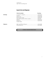
Table of Contents Page
User’s Guide ............................................................... 1
Reference Guide ....................................................... 35
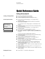
Quick Reference Guide ............................................ 60
Always state Serial No and Voltage/frequency if you have technical questions or when ordering spare parts.
You will find the Serial No. and Voltage on the type plate of the machine itself. We may also need the Date
and Article No of the manual. This information is found on the front cover.
The following restrictions should be observed, as violation of the restrictions may cause cancellation of
Struers legal obligations:
Instruction Manuals: Struers Instruction Manual may only be used in connection with Struers equipment
covered by the Instruction Manual.
Service Manuals: Struers Service Manual may only be used by a trained technician authorised by Struers.
The Service Manual may only be used in connection with Struers equipment covered by the Service Manual.
Struers assumes no responsibility for errors in the manual text/illustrations. The information in this manual is
subject to changes without notice. The manual may mention accessories or parts not included in the present
version of the equipment.
Original instructions. The contents of this manual is the property of Struers. Reproduction of any part of
this manual without the written permission of Struers is not allowed.
All rights reserved. © Struers 2012.
Struers A/S
Pederstrupvej 84
DK 2750 Ballerup
Denmark
Telephone +45 44 600 800
Fax +45 44 600 801

Accutom-50
Instruction Manual
Accutom-50
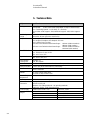
Safety Precaution Sheet
To be read carefully
before use
1. The operator should be fully instructed in the use of the machine, its
cut-off wheels and cup wheels according to the Instruction Manual and
the instructions for the cut-off wheels and cup wheels.
2. The machine must be placed on a safe and stable support table.
3. Be sure that the actual voltage corresponds to the voltage stated on the
back of the machine. The machine must be earthed.
4. Use only intact cut-off wheels or cup wheels. The cut-off wheels and
cup wheels must be approved for min. 5000 rpm. If other cut-off
wheels, saw blades or cup wheels are used, make sure that the speed
setting of Accutom-50 complies with the max. speed for the cut-off
wheels, saw blades or cup wheels.
5. Observe the current safety regulations for handling, mixing, filling,
emptying and disposal of the additive for cooling fluid.
6. The sample must be securely fixed in the specimen holder.
7. Do not touch the sample, the specimen holder head, the cut-off wheel
or cup wheel while positioning the sample with the POSITION controls.
8. Never try to open the cover before the cut-off wheel or cup wheel has
stopped completely.
The equipment should only be used for its intended purpose and as detailed in the Instruction Manual.
The equipment is designed for use with consumables supplied by Struers. If subjected to misuse, improper
installation, alteration, neglect, accident or improper repair, Struers will accept no responsibility for
damage(s) to the user or the equipment.
Dismantling of any part of the equipment, during service or repair, should always be performed by a qualified
technician (electromechanical, electronic, mechanical, pneumatic, etc.).

Accutom-50
Instruction Manual
Disposal
Equipment marked with a WEEE symbol contain electrical and
electronic components and must not be disposed of as general
waste.
Please contact your local authorities for information on the correct
method of disposal in accordance with national legislation.

Accutom-50
Instruction Manual
1
User’s Guide
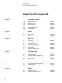
Table of Contents Page
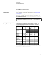
1. Getting Started 3
Checking the Contents of Packing ..................................................... 3
Placing Accutom-50 ........................................................................... 3
Getting Acquainted with Accutom-50 ................................................. 3
Supplying Power ................................................................................ 4
Changing the voltage setting .................................................... 4
Recirculation Unit ............................................................................... 6
Software Settings ............................................................................... 7
Configuration Menu ................................................................... 7
Setting the Language ................................................................ 8
2. Basic Operations
Using the Controls .............................................................................. 9
Front Panel Controls of Accutom-50 ......................................... 9
Groups of Keys ......................................................................... 9
Acoustic Signals ........................................................................ 9
Location of Main Switch ............................................................ 9
Front Panel Controls ........................................................................ 10
Display .................................................................................... 11
Reading the Display ......................................................................... 12
Changing/Editing Values .................................................................. 13
Numeric Values ....................................................................... 13
Alphanumeric Values .............................................................. 14
Positioning the Sample .................................................................... 15
Reference Position .................................................................. 15
Absolute Position .................................................................... 15
Relative Position ..................................................................... 15
Relative Zero ........................................................................... 15
Stop Position
........................................................................... 15
Selecting between Cutting and Grinding .......................................... 16
Cutting Display ........................................................................ 17
Grinding Display ...................................................................... 17
Cutting .............................................................................................. 18
Changing the Cut-off Wheel .................................................... 18
Clamping the Sample and Specimen Holder .......................... 19
Positioning the Sample ........................................................... 19
Setting the Cutting Parameters ........................................................ 20
Wheel ...................................................................................... 20
Speed ...................................................................................... 20
Feed ........................................................................................ 20
Force ....................................................................................... 20

Accutom-50
Instruction Manual
2
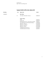
Cutting Mode .................................................................................... 21
Single Cut ............................................................................... 21
Multiple Cut ............................................................................. 21
Rotation ................................................................................... 22
Water ...................................................................................... 22
Starting the Cutting .......................................................................... 22
During Cutting .................................................................................. 23
Changing the Feed Speed ...................................................... 23
Retracting the sample ............................................................. 23
Force Limit Reached ............................................................... 23
Stopping the Cutting ......................................................................... 24
Automatic Stop ........................................................................ 24
Manual Stop ............................................................................ 24
Grinding ............................................................................................ 25
Changing the Cup Wheel ........................................................ 25
Connecting the Vacuum Chuck to the Vacuum System ......... 25
Clamping the Sample and Specimen Holder .......................... 26
Positioning the Sample ........................................................... 27
Positioning the Sample ........................................................... 27
Setting the Grinding Parameters ............................................. 28
Cup Wheel .............................................................................. 28
Speed ...................................................................................... 28
Y-Feed ............................................................................. 28
Sweeps ............................................................................ 28
X-Inc. ................................................................................... 28
Water ...................................................................................... 28
Rotation ................................................................................... 29
Removal Mode ................................................................................. 29
Starting the Grinding ........................................................................ 31
During Grinding ................................................................................ 31
Stopping the Grinding ...................................................................... 31
Automatic Stop ........................................................................ 31
Manual Stop ............................................................................ 31
Continuing the Grinding ................................................................... 31
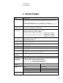
3. Maintenance
Daily Service .................................................................................... 32
Checking the Recirculation Unit .............................................. 32
Weekly Service ................................................................................ 33
Refilling the Cooling Water Tank ...................................................... 33
Emptying and Cleaning the Tank ............................................ 33
Refilling the Tank .................................................................... 33
Maintenance of Cut-off Wheels ........................................................ 34
Maintenance of Diamond and CBN Cut-off Wheels ................ 34
Storing of Abrasive Cut-off Wheels ......................................... 34
Maintenance of Cup Wheels ............................................................ 34

Accutom-50
Instruction Manual
3
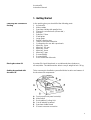
1. Getting Started
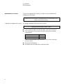
In the packing box you should find the following parts:
1 Accutom-50
2 Mains cables
1 Specimen Holder with parallel vice
1 Flange for cut-off wheels (42 mm dia.)
1 Stop pin
1 Spanner, 17mm
1 Small grate
1 Large grate
1 Debris collecting tray
1 Tube for vacuum connection
1 Cooling tube for use with cup-wheels
1 Allen key, 2 mm
1 Allen key, 2.5 mm
1 Allen key, 3 mm
1 Allen key, 4 mm
1 Allen key 5 mm
2 Screws M4x20
2 Screws M4x35
1 Set of Instruction Manuals
Accutom-50 should be placed on a stable and plane (tolerance
±1 mm) table. The table must be able to carry a weight of min. 50 kg.
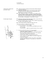
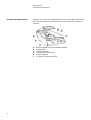
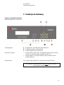
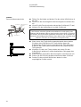
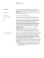
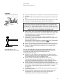
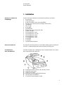
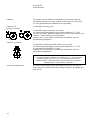
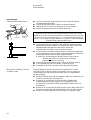
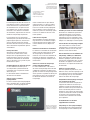
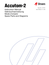
Take a moment to familiarise yourself with the location and names of
the Accutom-50 components.
A Front panel/Front panel control(s)
B Main switch
C Recirculation Cooling Unit
D Cut-off wheel/Cup wheel
E Specimen holder head
F Screw to vacuum connection
Checking the Contents of
Packing
Placing Accutom-50
Getting Acquainted with
Accutom-50

Accutom-50
Instruction Manual
4
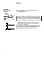
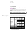
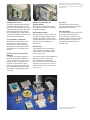
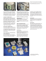
Always remember to switch the power off when installing electrical
equipment!
The factory setting for Accutom-50 is 240V.
Pull out the fuse holder from the cable terminal at the back of the
machine.
Pull out the voltage switch and turn it to the correct setting.
Voltage Required Setting
230 or 240V 240V
200 to 220V 200V
Note: The two additional settings, 110V and 120V are not to be used.
Reinsert the voltage switch.
Put the fuse holder back into the cable terminal.
Supplying Power
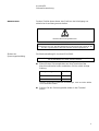
DANGER!
The machine must be earthed
IMPORTANT
Check that the mains voltage corresponds to the voltage stated
on the type plate on the back of the machine.
Changing the voltage setting
If the factory setting is not the correct setting for your mains supply the
setting can be changed from 240V to 220V:

Accutom-50
Instruction Manual
5
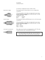
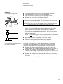
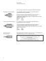
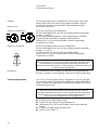
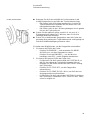
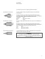
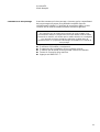
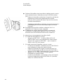
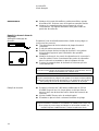
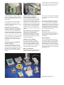
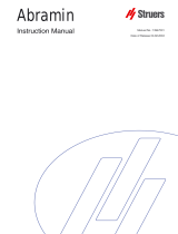
Accutom-50 is shipped with 2 types of Mains cables:
The 2-pin (European Schuko) plug is for use on single-phase
connections.
If the plug supplied on this cable is not approved in your country,
then the plug must be replaced with an approved plug. The leads
must be connected as follows:
Yellow/green: earth
Brown: line (live)
Blue: neutral
The 3-pin (North American NEMA) plug is for use on 3-phase power
connections.
If the plug supplied on this cable is not approved in your country,
then the plug must be replaced with an approved plug. The leads
must be connected as follows:
Green: earth
Black: line (live)
White: line (live)
Both cables are on the other end equipped with an IEC 320 cable
connector that has to be connected to the Accutom.
Single-phase Supply
3-phase Supply
Connection to the Machine
WARNING!
The output voltage from this cable is 200 – 240V and not 110V.
DO NOT use this cable to connect equipment that use a 110V power
supply. Failure to adhere to this may result in material damage.

Accutom-50
Instruction Manual
6
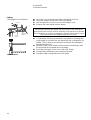
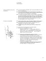
Pull out the recirculation tank.
Fill the tank with 3.88 l of water and 120 ml Struers Additive. The
water level should be 5 mm below the edge of the front hole in
the tank cover.
Check that the cover is fitted securely into place in the
recirculation tank and push the drawer with the recirculation tank
into place again.
Check that the end of the inlet tube has dropped into position.
Recirculation Unit
IMPORTANT
Always ensure that there is sufficient water in the tank as the recirculation
pump will be damaged if it is running dry.
Note:
Changing of cooling water should be done at least once a month.
IMPORTANT
Always maintain the correct concentration of Struers Additive in the cooling
water (percentage stated on the container of the Additive). Remember to
add Struers Additive each time you refill with water.
Do not use any oil, petrol, or turpentine-based additives, only Struers
additive.

Accutom-50
Instruction Manual
7
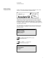
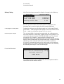
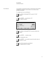
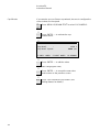
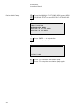
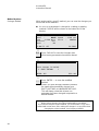
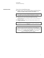
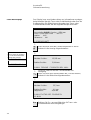
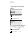
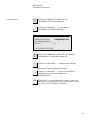
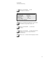
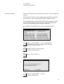
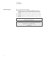
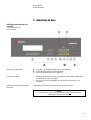
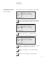
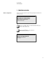
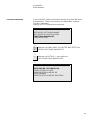
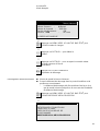
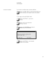
Switch on the power at the main switch located at the back of the
machine. The following display will appear briefly:
Afterwards the display will change to the same screen which was
shown before Accutom-50 was switched off, usually a cutting or
grinding method. When switching Accutom-50 on for the first time,
the display to appear should be the MAIN MENU. If the heading in
the display is different, press Esc, until the MAIN MENU appears. (A
long beep can be heard)
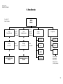
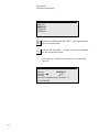
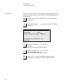
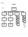
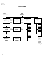
The MAIN MENU is the highest level in the menu structure. From
here you can go to configuration, manual functions and cutting or
grinding methods.
MAIN MENU
CUTTING METHODS
GRINDING METHODS
MANUAL FUNCTIONS
CONFIGURATION
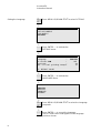
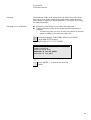
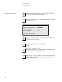
Press MENU UP/DOWN
to select
CONFIGURATION.
Press ENTER
to activate the
CONFIGURATION menu.
CONFIGURATION
CUT-OFF WHEELS
CUP WHEELS
OPTIONS
Software Settings
Configuration Menu

Accutom-50
Instruction Manual
8
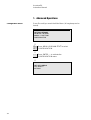
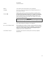
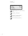
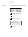
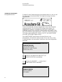
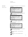
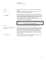
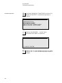
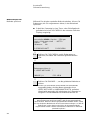
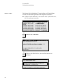
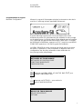
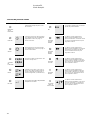
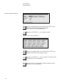
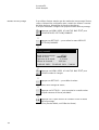
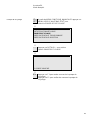
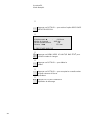
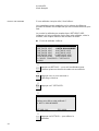
Press MENU UP/DOWN
to select OPTIONS.
CONFIGURATION
CUT-OFF WHEELS
CUP WHEELS
OPTIONS
Press ENTER
to activate the
OPTIONS menu.
OPTIONS
Language : ENGLISH
X-retract : OFF
Contrast : 40
No. of final grinding sweeps: 15
F1: DEFAULT VALUE
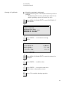
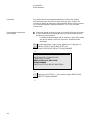
Press ENTER
to activate the
LANGUAGE Menu.
LANGUAGE
ENGLISH
DEUTSCH
FRANÇAIS
ESPAÑOL
Press MENU UP/DOWN
to select the Language
you prefer.
Press ENTER
to accept the language.
The OPTIONS Menu now appears in the language
you have chosen.
Setting the Language

Accutom-50
Instruction Manual
9
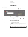
2. Basic Operations
A Programming and monitoring functions
B Positioning of the specimen holder
C Start/stop of Accutom-50
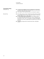
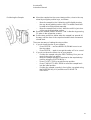
Short Beep: when a key is pressed, a short beep indicates that
the command has been accepted.
Long Beep: a long beep indicates that the key is inactive at that
moment.
The main switch is located on the back of the machine.
Using the Controls
Front Panel Controls
of Accutom-50
Groups of Keys
Acoustic Signals
Location of Main Switch
Please Note...
The contents of the program memory are not lost when the main switch is
turned off.

Accutom-50
Instruction Manual
10
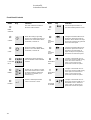
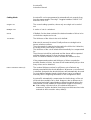
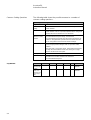
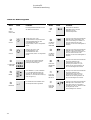
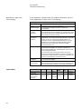
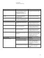
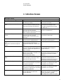
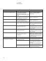
Name Key Function
Name Key Function
MAIN
SWITCH
The main switch is located on
the back of the machine.
ESC
Esc Leaves the present menu or
specimen holder position screen.
START Starts the cutting or grinding
process according to the pre-set
method. The recirculation water,
if selected, is turned on.
FAST
POSITION
LEFT
Changes to POSITION menu or
moves the specimen holder to
the left in the X-direction in steps
of 100 µm. Keep the key pressed
to increase the speed.
STOP Stops the cutting or grinding
process. The recirculation water,
if selected, is turned off.
FAST
POSITION
RIGHT
Changes to POSITION menu or
moves the specimen holder to
the right in the X-direction in
steps of 100 µm. Keep the key
pressed to increase the speed.
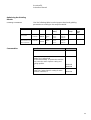
FUNCTION
KEYS
F1/F2
F3/F4
Controls for various purposes.
See the bottom of the individual
screens.
POSITION
LEFT
Changes to POSITION menu or
moves the specimen holder slowly
to the left in the X-direction in
steps of 5 µm. Keep the key
pressed to increase the speed.
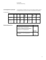
MENU
Scrolls up () or down () in the
menu tree structure of Accutom-
50. When setting a parameter
the value is increased () or
decreased (
).
POSITION
RIGHT
Changes to POSITION menu or
moves the specimen holder slowly
to the right in the X-direction in
steps of 5 µm. Keep the key
pressed to increase the speed.
ENTER Selects a marked parameter
value or chooses a menu.
POSITION
UP/DOWN
/
Changes to POSITION menu or
moves the specimen holder up- or
downwards in the Y-direction in
steps of 100 µm. Keep the key
pressed to increase the speed.
Front Panel Controls

Accutom-50
Instruction Manual
11
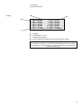
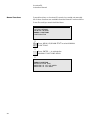
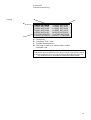
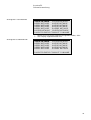
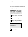
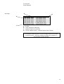
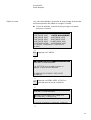
SELECT CUTTING METHOD
1.EMPTY METHOD 2.EMPTY METHOD
3.EMPTY METHOD 4.EMPTY METHOD
5.EMPTY METHOD 6.EMPTY METHOD
7.EMPTY METHOD 8.EMPTY METHOD
9.EMPTY METHOD 10.EMPTY METHOD
11.EMPTY METHOD 12.EMPTY METHOD
F1:COPY F2:INSERT F3:RESET F4:RENAME
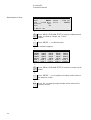
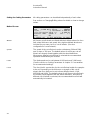
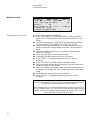
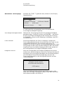
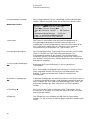
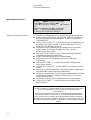
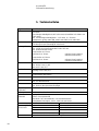
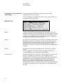
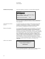
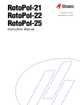
A Heading
B Inverted text. Cursor
C Function key options
D Arrow indicates, that there are more lines in the picture
Display
Please Note
The examples of display screens in this Instruction Manual show a number
of possible texts. The actual display screen may differ from the examples in
the Instruction Manual.
B
C
A
D

Accutom-50
Instruction Manual
12
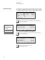
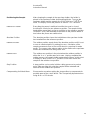
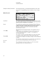
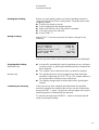
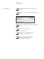
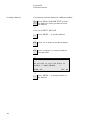
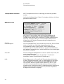
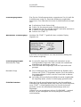
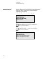
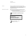
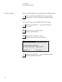
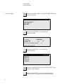
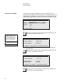
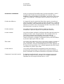
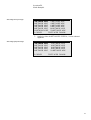
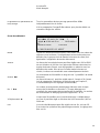
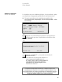
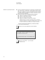
The display can show various kinds of information, for example about
the cutting or grinding method or about the sample position. A screen
for a cutting or grinding method could look as the following example:
Cutting Method: 1. EMPTY METHOD
Wheel : B0D15 Speed : 2700 rpm
Feed :0.100 mm/s Force : MEDIUM
Rotation: OFF
Water : ON
F1:MULTI. CUT
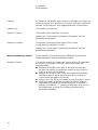
Pressing one of the X-axis positioning keys will change the
screen to the following:
X-POSITIONS
Absolute Position: 15.255 mm
Relative Position: 5.000 mm
F1:RESET F2:ADD F3:MOVE TO REL. ZERO
F2:ADD is only available in cutting methods.
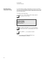
Pressing one of the Y-axis positioning keys will change the
screen to the following:
Y-POSITIONS
Absolute Position: 55.7 mm
Relative Position: 0.0 mm
Stop Position: 20.0 mm
F1:RESET F2:SET STOP F3:MOVE TO REL.ZERO
Esc
Press Esc, to return to the cutting or
grinding method screen.
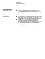
Reading the Display
The “heavy” arrows on the
display indicate the
direction in which the
sample holder is moved,
for example:
X-POSITIONS
Y-POSITIONS

Accutom-50
Instruction Manual
13
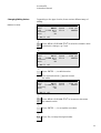
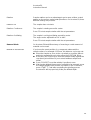
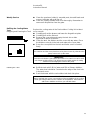
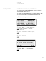
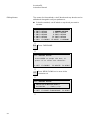
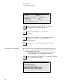
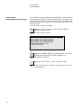
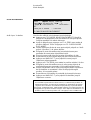
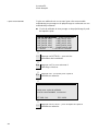
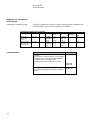
Depending on the type of value, there are two different ways of
editing.
Cutting Method: 1. EMPTY METHOD
Wheel : B0D15 Speed : 2700 rpm
Feed :0.100 mm/s Force : MEDIUM
Rotation: OFF
Water : ON
F1:MULTI. CUT
Press MENU UP/DOWN
to select the numeric value
you want to change, e.g. Feed:
Cutting Method: 1. EMPTY METHOD
Wheel : B0D15 Speed : 2700 rpm
Feed :0.100 mm/s Force : MEDIUM
Rotation: OFF
Water : ON
F1:MULTI. CUT
Press ENTER
, to edit the value.
Two square brackets [ ] appear around
the value.
Cutting Method: 1. EMPTY METHOD
Wheel : B0D15 Speed : 2700 rpm
Feed [0.100]mm/s Force : MEDIUM
Rotation: OFF
Water : ON
F1:MULTI. CUT
Press MENU UP/DOWN
to increase or decrease
the numeric value.
Press ENTER
, to accept the new value.
or
Esc
Press Esc, to keep the original value.
Changing/Editing Values
Numeric Values

Accutom-50
Instruction Manual
14
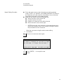
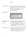
Cutting Method: 1. EMPTY METHOD
Wheel : B0D15 Speed : 2700 rpm
Feed :0.100 mm/s Force : MEDIUM
Rotation: OFF
Water : ON
F1:MULTI. CUT
Press MENU UP/DOWN
to select the alphanumeric
value you want to change, e.g. Cut-off
wheel:
Press ENTER
, to edit the value.
A submenu appears.
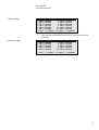
CUT-OFF WHEELS
M0D08 M1D08 M0D10 M1D10 M0D13
M1D13 B0D13 B0C13 50A13 30A13
SAW13 M0D15 M1D15 E0D15 B0D15
B0C15 50A15 40A15 10S15 30A15
USER 1 USER 2 USER 3 USER 4 USER 5
USER 6 USER 7 USER 8 USER 9 USER10
Press MENU UP/DOWN
to select the correct cut-off
wheel.
Press ENTER
, to accept the new value and to return to
the previous screen.
or
Esc
Press Esc, to keep the original value and to return to the
previous screen.
Alphanumeric Values

Accutom-50
Instruction Manual
15
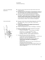
After clamping the sample in the specimen holder, the holder is
placed in the specimen holder head and fixed there. To move the
specimen holder and the sample, the POSITION keys are
used. The display shows the position in either X- or Y- direction.
Every time the power is switched on while the cover is closed,
Accutom-50 checks its own reference position. The sample holder
head will be moved back as far as possible, to the reference position
(X=0.000 Y=0.0), and thereafter it will return to the position where it
was before the power was switched on.
The absolute position shows the total distance the specimen holder
has travelled from the reference position.
The relative position equals that of the absolute position until it is set
to zero at a desired point. By setting it to zero, calculation of the
sample movement close to the cut-off wheel or cup wheel is made
easier. The screen value always relates to the distance the specimen
holder has travelled since being set to zero.
The relative zero position is the point where the relative position in
either the X- or Y- position was set to zero. Having completed the
cutting process, the sample holder automatically returns to this point.
Pressing F3 when in the X-or Y- position screen also returns the
sample to the relative zero position.
A stop position can be set to halt the cutting process at a precise
point. After reaching this point the sample will be retracted and
returned to the relative zero position.
Please make sure when setting the stop position to compensate for
possible wear of the cut-off wheel. This is especially important when
using Al2O3
or SiC wheels.
Positioning the Sample
Reference Position
Absolute Position
Relative Position
Relative Zero
Stop Position
Compensating for Wheel Wear

Accutom-50
Instruction Manual
16
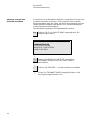
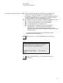
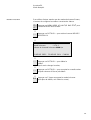
To select between cutting and grinding you must be in the Main
Menu. As Accutom-50 always starts up in the same state as when
the voltage was switched of last time, it might be necessary to go
back to the Main Menu.
To go back to the Main Menu:
Esc
Press Esc, until the MAIN MENU display appears.
(A long beep can be heard).
MAIN MENU
CUTTING METHODS
GRINDING METHODS
MANUAL FUNCTIONS
CONFIGURATION
Press MENU UP/DOWN
to select between
CUTTING METHODS and GRINDING METHODS.
Press ENTER
, to accept the selection.
If you selected CUTTING METHODS, the
screen will appear as follows.
Selecting between
Cutting and Grinding
La page est en cours de chargement...
La page est en cours de chargement...
La page est en cours de chargement...
La page est en cours de chargement...
La page est en cours de chargement...
La page est en cours de chargement...
La page est en cours de chargement...
La page est en cours de chargement...
La page est en cours de chargement...
La page est en cours de chargement...
La page est en cours de chargement...
La page est en cours de chargement...
La page est en cours de chargement...
La page est en cours de chargement...
La page est en cours de chargement...
La page est en cours de chargement...
La page est en cours de chargement...
La page est en cours de chargement...
La page est en cours de chargement...
La page est en cours de chargement...
La page est en cours de chargement...
La page est en cours de chargement...
La page est en cours de chargement...
La page est en cours de chargement...
La page est en cours de chargement...
La page est en cours de chargement...
La page est en cours de chargement...
La page est en cours de chargement...
La page est en cours de chargement...
La page est en cours de chargement...
La page est en cours de chargement...
La page est en cours de chargement...
La page est en cours de chargement...
La page est en cours de chargement...
La page est en cours de chargement...
La page est en cours de chargement...
La page est en cours de chargement...
La page est en cours de chargement...
La page est en cours de chargement...
La page est en cours de chargement...
La page est en cours de chargement...
La page est en cours de chargement...
La page est en cours de chargement...
La page est en cours de chargement...
La page est en cours de chargement...
La page est en cours de chargement...
La page est en cours de chargement...
La page est en cours de chargement...
La page est en cours de chargement...
La page est en cours de chargement...
La page est en cours de chargement...
La page est en cours de chargement...
La page est en cours de chargement...
La page est en cours de chargement...
La page est en cours de chargement...
La page est en cours de chargement...
La page est en cours de chargement...
La page est en cours de chargement...
La page est en cours de chargement...
La page est en cours de chargement...
La page est en cours de chargement...
La page est en cours de chargement...
La page est en cours de chargement...
La page est en cours de chargement...
La page est en cours de chargement...
La page est en cours de chargement...
La page est en cours de chargement...
La page est en cours de chargement...
La page est en cours de chargement...
La page est en cours de chargement...
La page est en cours de chargement...
La page est en cours de chargement...
La page est en cours de chargement...
La page est en cours de chargement...
La page est en cours de chargement...
La page est en cours de chargement...
La page est en cours de chargement...
La page est en cours de chargement...
La page est en cours de chargement...
La page est en cours de chargement...
La page est en cours de chargement...
La page est en cours de chargement...
La page est en cours de chargement...
La page est en cours de chargement...
La page est en cours de chargement...
La page est en cours de chargement...
La page est en cours de chargement...
La page est en cours de chargement...
La page est en cours de chargement...
La page est en cours de chargement...
La page est en cours de chargement...
La page est en cours de chargement...
La page est en cours de chargement...
La page est en cours de chargement...
La page est en cours de chargement...
La page est en cours de chargement...
La page est en cours de chargement...
La page est en cours de chargement...
La page est en cours de chargement...
La page est en cours de chargement...
La page est en cours de chargement...
La page est en cours de chargement...
La page est en cours de chargement...
La page est en cours de chargement...
La page est en cours de chargement...
La page est en cours de chargement...
La page est en cours de chargement...
La page est en cours de chargement...
La page est en cours de chargement...
La page est en cours de chargement...
La page est en cours de chargement...
La page est en cours de chargement...
La page est en cours de chargement...
La page est en cours de chargement...
La page est en cours de chargement...
La page est en cours de chargement...
La page est en cours de chargement...
La page est en cours de chargement...
La page est en cours de chargement...
La page est en cours de chargement...
La page est en cours de chargement...
La page est en cours de chargement...
La page est en cours de chargement...
La page est en cours de chargement...
La page est en cours de chargement...
La page est en cours de chargement...
La page est en cours de chargement...
La page est en cours de chargement...
La page est en cours de chargement...
La page est en cours de chargement...
La page est en cours de chargement...
La page est en cours de chargement...
La page est en cours de chargement...
La page est en cours de chargement...
La page est en cours de chargement...
La page est en cours de chargement...
La page est en cours de chargement...
La page est en cours de chargement...
La page est en cours de chargement...
La page est en cours de chargement...
La page est en cours de chargement...
La page est en cours de chargement...
La page est en cours de chargement...
La page est en cours de chargement...
La page est en cours de chargement...
La page est en cours de chargement...
La page est en cours de chargement...
La page est en cours de chargement...
La page est en cours de chargement...
La page est en cours de chargement...
La page est en cours de chargement...
La page est en cours de chargement...
La page est en cours de chargement...
La page est en cours de chargement...
La page est en cours de chargement...
La page est en cours de chargement...
La page est en cours de chargement...
La page est en cours de chargement...
La page est en cours de chargement...
La page est en cours de chargement...
La page est en cours de chargement...
La page est en cours de chargement...
La page est en cours de chargement...
La page est en cours de chargement...
La page est en cours de chargement...
La page est en cours de chargement...
La page est en cours de chargement...
La page est en cours de chargement...
La page est en cours de chargement...
La page est en cours de chargement...
La page est en cours de chargement...
La page est en cours de chargement...
La page est en cours de chargement...
La page est en cours de chargement...
La page est en cours de chargement...
La page est en cours de chargement...
La page est en cours de chargement...
La page est en cours de chargement...
La page est en cours de chargement...
La page est en cours de chargement...
La page est en cours de chargement...
La page est en cours de chargement...
La page est en cours de chargement...
La page est en cours de chargement...
La page est en cours de chargement...
La page est en cours de chargement...
La page est en cours de chargement...
La page est en cours de chargement...
La page est en cours de chargement...
La page est en cours de chargement...
La page est en cours de chargement...
La page est en cours de chargement...
La page est en cours de chargement...
La page est en cours de chargement...
La page est en cours de chargement...
La page est en cours de chargement...
La page est en cours de chargement...
La page est en cours de chargement...
La page est en cours de chargement...
La page est en cours de chargement...
La page est en cours de chargement...
La page est en cours de chargement...
La page est en cours de chargement...
La page est en cours de chargement...
La page est en cours de chargement...
La page est en cours de chargement...
-
 1
1
-
 2
2
-
 3
3
-
 4
4
-
 5
5
-
 6
6
-
 7
7
-
 8
8
-
 9
9
-
 10
10
-
 11
11
-
 12
12
-
 13
13
-
 14
14
-
 15
15
-
 16
16
-
 17
17
-
 18
18
-
 19
19
-
 20
20
-
 21
21
-
 22
22
-
 23
23
-
 24
24
-
 25
25
-
 26
26
-
 27
27
-
 28
28
-
 29
29
-
 30
30
-
 31
31
-
 32
32
-
 33
33
-
 34
34
-
 35
35
-
 36
36
-
 37
37
-
 38
38
-
 39
39
-
 40
40
-
 41
41
-
 42
42
-
 43
43
-
 44
44
-
 45
45
-
 46
46
-
 47
47
-
 48
48
-
 49
49
-
 50
50
-
 51
51
-
 52
52
-
 53
53
-
 54
54
-
 55
55
-
 56
56
-
 57
57
-
 58
58
-
 59
59
-
 60
60
-
 61
61
-
 62
62
-
 63
63
-
 64
64
-
 65
65
-
 66
66
-
 67
67
-
 68
68
-
 69
69
-
 70
70
-
 71
71
-
 72
72
-
 73
73
-
 74
74
-
 75
75
-
 76
76
-
 77
77
-
 78
78
-
 79
79
-
 80
80
-
 81
81
-
 82
82
-
 83
83
-
 84
84
-
 85
85
-
 86
86
-
 87
87
-
 88
88
-
 89
89
-
 90
90
-
 91
91
-
 92
92
-
 93
93
-
 94
94
-
 95
95
-
 96
96
-
 97
97
-
 98
98
-
 99
99
-
 100
100
-
 101
101
-
 102
102
-
 103
103
-
 104
104
-
 105
105
-
 106
106
-
 107
107
-
 108
108
-
 109
109
-
 110
110
-
 111
111
-
 112
112
-
 113
113
-
 114
114
-
 115
115
-
 116
116
-
 117
117
-
 118
118
-
 119
119
-
 120
120
-
 121
121
-
 122
122
-
 123
123
-
 124
124
-
 125
125
-
 126
126
-
 127
127
-
 128
128
-
 129
129
-
 130
130
-
 131
131
-
 132
132
-
 133
133
-
 134
134
-
 135
135
-
 136
136
-
 137
137
-
 138
138
-
 139
139
-
 140
140
-
 141
141
-
 142
142
-
 143
143
-
 144
144
-
 145
145
-
 146
146
-
 147
147
-
 148
148
-
 149
149
-
 150
150
-
 151
151
-
 152
152
-
 153
153
-
 154
154
-
 155
155
-
 156
156
-
 157
157
-
 158
158
-
 159
159
-
 160
160
-
 161
161
-
 162
162
-
 163
163
-
 164
164
-
 165
165
-
 166
166
-
 167
167
-
 168
168
-
 169
169
-
 170
170
-
 171
171
-
 172
172
-
 173
173
-
 174
174
-
 175
175
-
 176
176
-
 177
177
-
 178
178
-
 179
179
-
 180
180
-
 181
181
-
 182
182
-
 183
183
-
 184
184
-
 185
185
-
 186
186
-
 187
187
-
 188
188
-
 189
189
-
 190
190
-
 191
191
-
 192
192
-
 193
193
-
 194
194
-
 195
195
-
 196
196
-
 197
197
-
 198
198
-
 199
199
-
 200
200
-
 201
201
-
 202
202
-
 203
203
-
 204
204
-
 205
205
-
 206
206
-
 207
207
-
 208
208
-
 209
209
-
 210
210
-
 211
211
-
 212
212
-
 213
213
-
 214
214
-
 215
215
-
 216
216
-
 217
217
-
 218
218
-
 219
219
-
 220
220
-
 221
221
-
 222
222
-
 223
223
-
 224
224
-
 225
225
-
 226
226


dans d''autres langues
- English: Struers Accutom-50 User manual
- Deutsch: Struers Accutom-50 Benutzerhandbuch
Documents connexes
-
 Struers Unitom-5 Manuel utilisateur
-
 Struers Prepamatic-2 Manuel utilisateur
-
 Struers Accutom-2 Manuel utilisateur
-
 Struers Abramin Manuel utilisateur
-
 Struers RotoPol-21 Manuel utilisateur
-
 Struers Discotom-50 Manuel utilisateur
-
 Struers ProntoPress-10 Manuel utilisateur
-
 Struers Unitom-50 Manuel utilisateur
-
 Struers PDM-Force-20 Manuel utilisateur
-
 Struers Tenupol-3 Manuel utilisateur


