
Manual No.: 15137001
Date of Release 26.07.2006
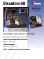
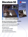
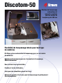
Discotom-50
Instruction Manual

Discotom-50
Instruction Manual
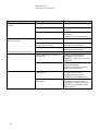
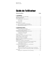
Table of Contents Page
User’s Guide ..............................................................1
Reference Guide.......................................................21
Quick Reference Guide............................................33
A
lways state Serial No and Voltage/frequency if you have technical questions or when ordering spare parts.
You will find the Serial No. and Voltage on the type plate of the machine itself. We may also need the Date
and Article No of the manual. This information is found on the front cover.
The following restrictions should be observed, as violation of the restrictions may cause cancellation of
Struers legal obligations:
Instruction Manuals: Struers Instruction Manuals may only be used in connection with Struers equipment
covered by the Instruction Manual.
Service Manuals: Struers Service Manuals may only be used by a trained technician authorised by Struers.
The Service Manual may only be used in connection with Struers equipment covered by the Service Manual.
Struers assumes no responsibility for errors in the manual text/illustrations. The information in this manual is
subject to change without notice. The manual may mention accessories or parts not included in the present
version of the equipment.
The contents of this manual are the property of Struers. Reproduction of any part of this manual without the
written permission of Struers is not allowed.
A
ll rights reserved. © Struers 2006.
Struers A/S
Pederstrupvej 84
DK-2750 Ballerup
Denmark
Telephone +45 44 600 800
Fax +45 44 600 801

Discotom-50
Instruction Manual
Discotom-50
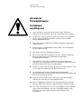
Safety Precaution Sheet
To be read carefully
before use
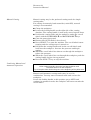
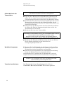
1. The operator(s) should be fully instructed in the use of the machine and
its cut-off wheels according to the Instruction Manual and the
instructions for the cut-off wheels.
2. The machine must be placed on a safe and stable support table. All
safety functions and guards of the machine must be in working order.
3. The unit must be installed in compliance with local safety regulations.
4. Use only intact cut-off wheels. The cut-off wheels must be approved for
min. 50 m/s.
5. The machine is not for use with saw-blade type cut-off wheels.
6. Observe the current safety regulations for handling, mixing, filling,
emptying and disposal of the additive for cooling fluid.
7. The workpiece must be securely fixed in the quick-clamping device or
similar. Large or sharp workpieces must be handled in a safe way.
8. Do not work on or around cutting table when the table is repositioned
using the forwards/backwards key (v V).
9. To achieve maximum safety and lifetime of the machine, use only
original Struers consumables.
10. The cutting handle should be lowered slowly and carefully, in order to
avoid breaking the cut-off wheel.
11. Struers recommends the use of an exhaust system as the materials
being cut may emit harmful gasses or dust.
12. The machine emits only moderate noise. However, the cutting process
itself may emit noise, depending on the nature of the workpiece. In
such cases, the use of hearing protection is recommended.
13. The machine must be disconnected from the mains prior to any service.

Discotom-50
Instruction Manual
14. Do not put your hand through the rubber curtain during operation of the
machine.
15. Use of working gloves is recommended as workpieces may be both
very hot and produce sharp edges.
The equipment is designed for use with consumables supplied by Struers. If subjected to misuse, improper
installation, alteration, neglect, accident or improper repair, Struers will accept no responsibility for
damage(s) to the user or the equipment.
Dismantling of any part of the equipment, during service or repair, should always be performed by a qualified
technician (electromechanical, electronic, mechanical, pneumatic, etc.)

Discotom-50
Instruction Manual
1
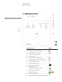
User’s Guide
Table of Contents Page
1. Getting Started
Checking the Contents of the Packing Box ..................................... 2
Unpacking Discotom-50.................................................................... 2
Placing Discotom-50 ......................................................................... 2
Getting Acquainted with Discotom-50............................................. 3
Front View ............................................................................... 3
Rear View................................................................................. 4
Noise Level........................................................................................ 4
Power Supply .................................................................................... 4
Connecting the Recirculation Cooling Unit (optional).................... 5
2. Basic Operation
Using the Controls............................................................................ 6
Front Panel Controls of Discotom-50 ..................................... 6
Front Panel Controls ........................................................................7
Cooling Valve Positions....................................................................8
Cutting position....................................................................... 8
Cleaning positions ................................................................... 8
Flush Hose ........................................................................................ 9
Cleaning of Flush Hose Nozzle ........................................................ 9
Light Diode and Beep Signals........................................................ 10
Using the Load Bar......................................................................... 11
Overload Protection ........................................................................ 11
Fitting or Changing the Cut-off Wheel.......................................... 12
Clamping the Workpiece ................................................................ 12
Positioning the Cutting Table........................................................ 12
Starting/Stopping the Cutting Process.......................................... 13
Automatic Cutting (AUTO mode)......................................... 13
Manual Cutting ..................................................................... 14
Combining Manual and Automatic Operation..................... 14
Programmable Stop............................................................... 15
Variable Rotational Speed ....................................................16
Feed Speed............................................................................. 17
Material-specific Cut-off Wheels ..........................................18
Using CBN or Diamond Cut-off wheels ...............................19
Cleaning .......................................................................................... 20
Flushing the Cutting Chamber............................................. 20

Discotom-50
Instruction Manual
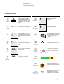
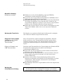
1. Getting Started
In the packing box you should find the following parts:
Checking the Contents
of the Packing Box
1 Spanner (24 mm) for cut-off wheel
1 Spanner (13 mm) for transport bolts
1 Connector pipe for water outlet
1 Filter for drain
1 Set of Service Documentation for
Siemens frequency converter
1 Set of Instruction Manuals
Remove the screws underneath the pallet to release the
Discotom-50.
Unpacking Discotom-50
Discotom-50 should be placed on a table capable of carrying min.
150 kg.
Placing Discotom-50
2

Discotom-50
Instruction Manual
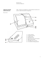
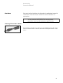
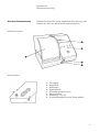
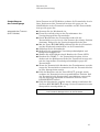
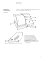
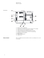
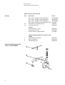
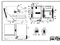
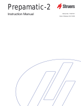
Take a moment to familiarise yourself with the location and
names of the Discotom-50 components.
Getting Acquainted
with Discotom-50
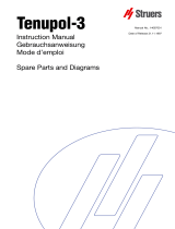
Front View
c Cutting handle
d Instrument panel
e Cooling valve
f Flush hose inlet
g Protection guard, with window
h Main power switch
i Secondary fuse, 3.15AT
j Cut-off wheel locking handle
3

Discotom-50
Instruction Manual
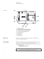
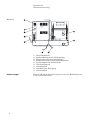
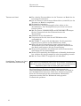
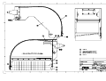
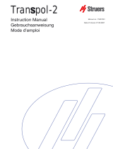
4
Rear View
c Upper back plate
d Reset button for recirculation pump
e Cable inlet for recirculation pump
f Electrical cable for power supply
g Cut-off wheel locking handle
h Overflow drain
i Water inlet
j Exhaust hose
k Water outlet
Approx. 67 dB (A) measured at idle running, at a distance of
1.0 m/39.4” from the machine.
Noise Level
First check that the mains voltage corresponds to the voltage
stated on the type plate on the side of the machine.
Power Supply
Discotom-50 is factory mounted with an electric cable. Mount a
plug on the cable:
Black and brown = phase
Yellow/green = earth
Important
Residual Current Circuit-Breaker must be min. 20 mA.

Discotom-50
Instruction Manual
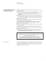
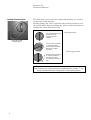
Connect the Recirculation Cooling Unit (optional), product code
TRECA as follows:
Connecting the Recirculation
Cooling Unit (optional)
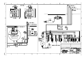
To connect the electric cable for the recirculation pump, remove
the upper back plate on Discotom-50 and follow the
instructions on the wiring diagram found on the inside of the
back plate.
Check that when the power is turned on, the pump rotates in
the direction indicated by an arrow on the top of the pump. If
not, switch two of the phases to the pump motor and re-check.
Replace the back plate.
Clamp the inlet hose to the pump and attach the other end to
the water inlet on Discotom-50 i.
Attach the connector pipe to the water outlet k, mount the
large outlet hose and secure with the large hose clamp.
Place the tank on the trolley.
Place a disposable plastic insert (EXOSP) in the tank and fold
it over the rim.
Fill the tank with 63 l water and 2 l Struers Additive. The
water level should be 8-10 cm below the upper rim of the tank.
Fit the tank lid and sieve.
Roll the trolley into its proper position and place the outlet and
overflow drain hoses k & h inside the cooling water tank.
Adjust the hose lengths if necessary.
IMPORTANT
c Too high a level of coolant in the tank might damage the pump. To avoid
this, place the disposable insert so that the pre-punched hole is in front of
the overflow aperture in the tank.
d Always maintain the correct concentration of Struers Additive in the
cooling water (percentage stated on the Additive container).
Remember to top up with Struers Additive each time you refill with water.
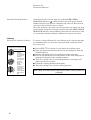
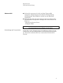
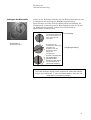
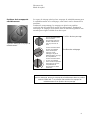
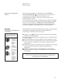
If the recirculation pump is overloaded or blocked, a thermal cut-
out will switch the pump off. This safety cut-out must be reset by
pushing the red button on the back of the Discotom-50 d before
the machine can be restarted.
Re-set button
5

Discotom-50
Instruction Manual
2. Basic Operation
Using the Controls
Front Panel Controls
of Discotom-50
c
Control name Symbol
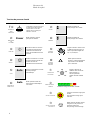
c Main power switch ...........................................................
d Power indicator light .........................................................Power
e Start key .............................................................................s
f Stop key .............................................................................o
g Auto key ..........................................................................Auto
h Auto mode indicator light..................................................Auto
i Forwards key.......................................................................v
j Backwards key ....................................................................V
k Feed Speed knob.............................................................
l Feed Speed Reduced indicator light.................................
1 Rotational speed knob...................................................
2 Load bar.....................................................................
3 Emergency stop................................................................
4 Emergency stop/overload indicator light...........................o
6

Discotom-50
Instruction Manual
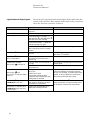
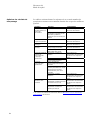
Front Panel Controls
Name Key Function Name Key Function
c
MAIN
SWITCH
The main power switch is
located on the right hand
side of Discotom-50. Turn
clockwise to switch on the
power.
i
FORWARDS v Moves cutting table
forwards.
d
POWER
INDICATOR
Power Lights when main power is
switched on. j
BACKWARDS V Moves cutting table
backwards.
e
START s Starts the machine. The cut-
off wheel starts rotating and
the cooling water is turned
on.
k
FEED SPEED
Regulates the feed speed of
the cutting table. The speed
can be set from 0.1-2.5
mm/sec.
f
STOP o Stops the machine. The cut-
off wheel stops rotating and
the cooling water is turned
off.
l
FEED SPEED
REDUCED
Lights when the feed speed
has been set too high and is
reduced by the machine.
g
AUTO
Auto Select or deselect automatic
cutting mode 1
ROTATIONAL
SPEED
Regulates the rotational
speed of the cut-off
wheel. The speed can be
set from 1000-3000 rpm.
h
AUTO
INDICATOR
Auto Lights when automatic
cutting mode selected. 2
Reflects the present motor load status.
LOAD BAR
3
EMERGENCY
STOP
Push the red button to stop.
Pull the red button to release.
4
EMERG. STOP
OVERLOAD
oLights when emergency stop
has been pressed or the
cutting motor is overloaded.
7

Discotom-50
Instruction Manual
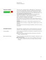
The flush hose, and a valve for cooling and cleaning, are located
on the front of the machine.
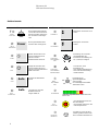
Cooling Valve Positions
During cutting, the valve is placed in the vertical position to cool
the cut-off wheel. During cleaning the valve is turned clockwise to
regulate the water flow of the hose.
8
For cut-off wheel cooling,
position the knob
vertically with dot
upwards.
Cutting position
Flush hose and
Cooling valve Turn the knob clockwise
to activate flushing
mode. Adjust flow while
flushing the cutting
chamber.
Cleaning positions
Turn the knob clockwise
to vertical position for
flushing the cutting
chamber with maximum
flow.
Please Note
After cleaning, turn cooling valve back to vertical position. START s can
not be activated unless the cooling valve is in the cutting position.

Discotom-50
Instruction Manual
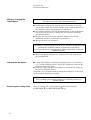
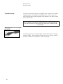
The nozzle of the flush hose is adjustable for additional control of
coolant flow. Turn the nozzle clockwise/counter-clockwise as
appropriate.
Flush Hose
IMPORTANT
Do not move the cooling valve to the cleaning position
until the flush hose is pointing inside the cutting chamber.
Cleaning of Flush Hose Nozzle
The flush hose nozzle may collect swarf, inhibiting flow. To clean,
unscrew nozzle head as shown, and rinse both parts under clean
water.
9

Discotom-50
Instruction Manual
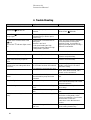
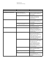
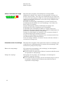
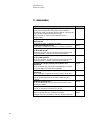
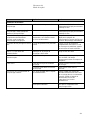
Discotom-50 is provided with various light diodes indicating the
status of the machine. Beep signals will sound if a key is pressed
when the function cannot be activated.
Light Diode and Beep Signals
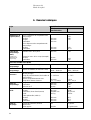
Status Explanation Comments
Green POWER indicator on The main power switch has been
turned on.
Green AUTO indicator on AUTO mode is active.
Beep signal You pressed AUTO, START s,
FORWARDS v or BACKWARDS V
while the motor was running.
You pressed START s while the
protection guard was open. Turn cooling valve to cutting position.
You pressed START s for cutting
while cooling valve isn’t in cutting
position.
Red STOP o indicator on The emergency stop has been
pressed. Release the emergency stop to shut off
the STOP o indicator.
Red STOP o indicator on
and beep signal The emergency stop has been
pressed and you tried to press
another key.
In AUTO mode: the feed speed is
too high.
10
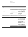
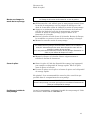
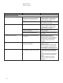
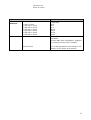
The machine automatically turns the feed
speed down.
Yellow FEED SPEED
REDUCED indicator on An AUTO cut has finished. Feed
speed reduced. Reduce feed speed or press any key.
Yellow FEED SPEED
REDUCED and
Red STOP o indicator lights
come on
Cutting motor overloaded due to
heavy use:
Material is too hard
Feed speed setting too high
Rotational speed setting too high
Cutting table is jammed
Press any key to stop the indicators.
Solve the problem causing the machine
to stop, for example, by reducing the feed
speed, or using a different cut-off wheel,
then release the emergency stop.
Red STOP o indicator and
LOAD BAR in red area Process halted.
Main motor or frequency inverter
overloaded or overheated.
Red STOP o indicator and
LOAD BAR in red area and
beep signal
START was pressed before re-
setting the warning indicator.
Press the STOP key o to re-set the
warning indicator and wait until the motor
or frequency inverter had cooled down.

Discotom-50
Instruction Manual
Discotom-50 is equipped with an LED load bar, indicating the
load on the cutting motor. The bar is divided into three areas; a
green area showing that the load on the cutting motor is OK, a
yellow area indicating that the load is near maximum and a red
area indicating overload of the motor.
Using the Load Bar
In automatic cutting mode, the feed speed is automatically
reduced on overload, i.e. if the red area is reached.
When cutting manually, the load bar serves as an indicator of
how much force is applied on the sample.
The machine may cut with the load bar in the yellow area for a
period of time depending on how hot the motor is when cutting is
started:
Starting with a hot motor, cutting will be stopped after a few
minutes.
Starting with a cold motor, cutting will be stopped after up to 20
minutes.
For continuous load, the feed speed should be reduced to a green
load level.
Discotom-50 is equipped with an overload protection to prevent
damage to the cutting motor and the recirculation pump motor.
Overload Protection
If the cutting motor has been overloaded, a thermal cut-out will
stop the motor.
Cutting Motor
Open the protection hood and allow the motor to cool down
before resuming cutting.
If the recirculation pump has been overloaded, a thermal cut-out
will stop the motor.
Recirculation Pump
To reset the pump, press the red re-set button on the rear of
the machine. Allow the motor to cool down, before resuming
cutting.
11

Discotom-50
Instruction Manual
Fitting or Changing the
Cut-off Wheel IMPORTANT
The spindle of Discotom-50 is left-hand threaded.
If Discotom-50 has been used for manual cutting, secure the
cut-off wheel with the locking handle on the right hand side of
the machine before changing the cut-off wheel.
Press and hold down the black locking knob on the right-hand
side of the cut-off wheel, turning the cut-off wheel until the
spindle lock clicks.
Remove the nut with a fork spanner. Remove the flange,
cardboard washers and the old cut-off wheel.
Mount the new cut-off wheel.
IMPORTANT
Conventional cut-off wheels based on Al2O3/SiC abrasives should be placed
between two cardboard washers, to protect the cut-off wheel.
For maximum precision with diamond or CBN cut-off wheels, do not use
cardboard washers.
Mount the flange and the nut. Tighten carefully and release
the locking knob.
Clamp the workpiece with the clamping device of your choice
e.g. a quick clamping device. Place the workpiece between the
clamp and the back stop.
Clamping the Workpiece
Push the clamp towards the workpiece and lock the clamp on
the quick-clamping device.
Generally, it is recommended to clamp the workpiece as far back
in the cutting chamber as possible.
IMPORTANT
Prior to cutting, ensure that the workpiece is held firmly in place by a
clamping device.
Prior to cutting, the cutting table is positioned using the
FORWARDS v and BACKWARDS V keys.
Positioning the Cutting Table
12

Discotom-50
Instruction Manual
When the machine is used in AUTO mode the cut-off wheel is
stationary and the cutting table moves. In MANUAL mode the
cutting table is stationary and the operator moves the cut-off
wheel.
Starting/Stopping
the Cutting Process
Clamp the workpiece.
A
utomatic Cutting
(AUTO mode) Loosen the cut-off wheel locking handle situated on the right-
hand side of the cutting chamber.
Lower the cut-off wheel by pulling the cutting handle
downwards until the cut-off wheel is positioned ready to cut
the workpiece. Re-fasten the locking handle.
Press v FORWARDS to position the cutting table and the
workpiece just in front of the cut-off wheel.
Close the protection guard.
Set the desired feed speed and rotational speed.
Select AUTO mode by pressing the AUTO mode key.
Press START s; the cut-off wheel starts rotating and the
cooling water starts to flow. The cutting table moves forward
towards the cut-off wheel at the preset feed speed.
When the cutting table reaches the back of the cutting
chamber, the cut-off wheel automatically stops and the cutting
table returns to its start position.
If the machine is stopped with the STOP o key, the cutting
table will stay at the present position. To return the cutting
table to its start position, wait for the double beep and press
BACKWARDS V once.
If the protection guard has been opened, press and hold the
BACKWARDS key V to move the cutting table to its start
position.
Please Note
The cutting table will only move when AUTO mode is switched on.
13

Discotom-50
Instruction Manual
Manual cutting may be the preferred cutting mode for simple
cutting tasks.
Manual Cutting
For cutting of extremely hard materials (>1000 HV), manual
cutting is recommended.
Clamp the workpiece.
Loosen the locking handle on the right side of the cutting
chamber. The cutting handle is now easily moved up and down.
Position the cutting table and the workpiece under the cut-off
wheel with the FORWARDS v and BACKWARDS V keys.
Close the protection guard.
Ensure that AUTO mode is de-selected.
Press START s to start the machine. The cut-off wheel starts
rotating and the cooling water is turned on.
Pull down the cutting handle and let the cut-off wheel work
itself into the workpiece. Increase the pressure and begin
cutting.
When the cut-off wheel has almost cut through the workpiece
reduce the pressure.
When the cut-off wheel has cut through the workpiece push the
cutting handle back to its top position.
Press the STOP o key to stop the machine.
Combining Manual and
A
utomatic Operation
IMPORTANT
When cutting manually, the motor load bar should be used
to monitor the force on the workpiece.
Try to keep the motor load in the green or the beginning of the yellow area.
Manual and Automatic cutting modes may be used in
combination. You may start in manual mode and cut into the
workpiece.
Secure the locking handle in this position, press AUTO and
continue in automatic mode; the workpiece will move towards the
cut-off wheel.
14

Discotom-50
Instruction Manual
Discotom-50 is supplied with an automatic feature, allowing you
to pre-program a specific stop position.
Programmable Stop
Position the cutting table at the desired stop position using the
FORWARDS v and BACKWARDS V keys.
Set the stop position by pressing the STOP o key and holding
it down whilst activating the FORWARDS v key.
Use BACKWARDS V to move the cutting table clear of the cut-
off wheel. Place and clamp the workpiece and press START s.
The cutting table stops when it reaches the pre-set stop
position and the cutting table moves to the position from where
cutting was started.
Cancelling the Programmable
Stop
Cancel the stop position by pressing the STOP o key and
holding it down whilst activating the BACKWARDS V key.
Note
The stop position will also be cancelled when the machine is switched off.
15

Discotom-50
Instruction Manual
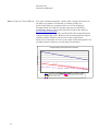
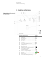
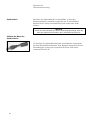
Discotom-50 is fitted with a variable rotational speed feature.
This allows you to optimise cutting quality and cut many different
materials using the same cut-off wheel. Thus materials as
different as aluminium and hardened steel can be cut using the
same cut-off wheel.
Variable Rotational Speed
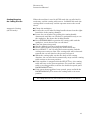
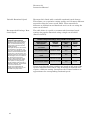
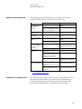
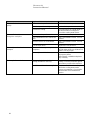
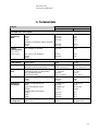
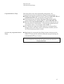
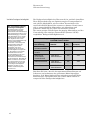
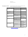
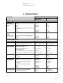
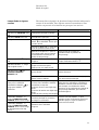
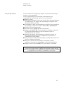
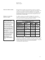
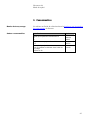
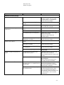
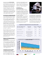
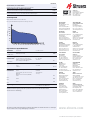
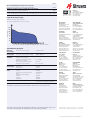
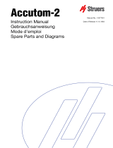
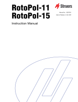
The table below is a guide to recommended rotational speed
settings for popular materials using a single cut-off wheel
(Struers 53UNI).
Recommended Settings, Rota-
tional Speed
16
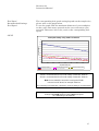
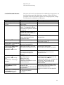
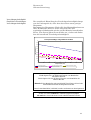
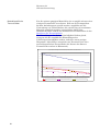
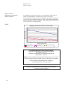
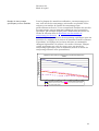
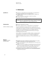
Rotational Speed Settings using 53UNI cut-off wheel
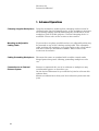
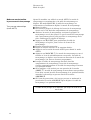
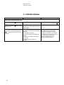
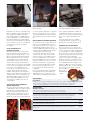
What happens when the
rotational speed changes?
Ordinary cut-off wheels, based on
bakelite-bonded siliciumcarbide
(SiC) or aluminiumoxide (Al2O3),
change their properties with the
rotational speed.
The higher the speed, the ‘harder’
the properties of the wheel, and
vice versa. The benefit of a higher
speed is that the wheel wears at a
slower rate. At the same time, the
workpiece becomes more prone to
heat damage, which is countered
by reducing the feed speed.
Using a slower rotational speed,
the same wheel becomes softer,
and capable of cutting through
harder materials, with less risk of
workpiece damage. The downside
is increased wheel wear.
Struers have optimised both
rotational and feed speed, as per
the table and graph shown.
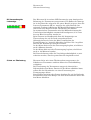
Metalog Guide
Description Material
Tested Hardness
(HV) Speed
(RPM)
Non ferrous
soft metal Aluminium 50-110 3000
Very ductile metal Stainless steel 220 2200
Medium soft ferrous
metal UHB IMPAX
Cold work tool steel 300 2200
Medium hard metal UHB IMPAX
Cold work tool steel 480 2000
Hard ferrous metal UHB ARNE
Cold work tool steel 750 1750
Please note that the above settings are based on lab tests of the
specific materials listed above. Any deviation in material will
require a different setting. Interpolate the Vickers hardness to
approximate the corresponding rotational speed.
La page est en cours de chargement...
La page est en cours de chargement...
La page est en cours de chargement...
La page est en cours de chargement...
La page est en cours de chargement...
La page est en cours de chargement...
La page est en cours de chargement...
La page est en cours de chargement...
La page est en cours de chargement...
La page est en cours de chargement...
La page est en cours de chargement...
La page est en cours de chargement...
La page est en cours de chargement...
La page est en cours de chargement...
La page est en cours de chargement...
La page est en cours de chargement...
La page est en cours de chargement...
La page est en cours de chargement...
La page est en cours de chargement...
La page est en cours de chargement...
La page est en cours de chargement...
La page est en cours de chargement...
La page est en cours de chargement...
La page est en cours de chargement...
La page est en cours de chargement...
La page est en cours de chargement...
La page est en cours de chargement...
La page est en cours de chargement...
La page est en cours de chargement...
La page est en cours de chargement...
La page est en cours de chargement...
La page est en cours de chargement...
La page est en cours de chargement...
La page est en cours de chargement...
La page est en cours de chargement...
La page est en cours de chargement...
La page est en cours de chargement...
La page est en cours de chargement...
La page est en cours de chargement...
La page est en cours de chargement...
La page est en cours de chargement...
La page est en cours de chargement...
La page est en cours de chargement...
La page est en cours de chargement...
La page est en cours de chargement...
La page est en cours de chargement...
La page est en cours de chargement...
La page est en cours de chargement...
La page est en cours de chargement...
La page est en cours de chargement...
La page est en cours de chargement...
La page est en cours de chargement...
La page est en cours de chargement...
La page est en cours de chargement...
La page est en cours de chargement...
La page est en cours de chargement...
La page est en cours de chargement...
La page est en cours de chargement...
La page est en cours de chargement...
La page est en cours de chargement...
La page est en cours de chargement...
La page est en cours de chargement...
La page est en cours de chargement...
La page est en cours de chargement...
La page est en cours de chargement...
La page est en cours de chargement...
La page est en cours de chargement...
La page est en cours de chargement...
La page est en cours de chargement...
La page est en cours de chargement...
La page est en cours de chargement...
La page est en cours de chargement...
La page est en cours de chargement...
La page est en cours de chargement...
La page est en cours de chargement...
La page est en cours de chargement...
La page est en cours de chargement...
La page est en cours de chargement...
La page est en cours de chargement...
La page est en cours de chargement...
La page est en cours de chargement...
La page est en cours de chargement...
La page est en cours de chargement...
La page est en cours de chargement...
La page est en cours de chargement...
La page est en cours de chargement...
La page est en cours de chargement...
La page est en cours de chargement...
La page est en cours de chargement...
La page est en cours de chargement...
La page est en cours de chargement...
La page est en cours de chargement...
La page est en cours de chargement...
La page est en cours de chargement...
La page est en cours de chargement...
La page est en cours de chargement...
La page est en cours de chargement...
La page est en cours de chargement...
La page est en cours de chargement...
La page est en cours de chargement...
La page est en cours de chargement...
La page est en cours de chargement...
La page est en cours de chargement...
La page est en cours de chargement...
La page est en cours de chargement...
La page est en cours de chargement...
La page est en cours de chargement...
La page est en cours de chargement...
La page est en cours de chargement...
La page est en cours de chargement...
La page est en cours de chargement...
La page est en cours de chargement...
La page est en cours de chargement...
La page est en cours de chargement...
La page est en cours de chargement...
La page est en cours de chargement...
La page est en cours de chargement...
La page est en cours de chargement...
La page est en cours de chargement...
La page est en cours de chargement...
La page est en cours de chargement...
La page est en cours de chargement...
La page est en cours de chargement...
La page est en cours de chargement...
La page est en cours de chargement...
La page est en cours de chargement...
La page est en cours de chargement...
La page est en cours de chargement...
La page est en cours de chargement...
La page est en cours de chargement...
La page est en cours de chargement...
La page est en cours de chargement...
La page est en cours de chargement...
La page est en cours de chargement...
La page est en cours de chargement...
La page est en cours de chargement...
-
 1
1
-
 2
2
-
 3
3
-
 4
4
-
 5
5
-
 6
6
-
 7
7
-
 8
8
-
 9
9
-
 10
10
-
 11
11
-
 12
12
-
 13
13
-
 14
14
-
 15
15
-
 16
16
-
 17
17
-
 18
18
-
 19
19
-
 20
20
-
 21
21
-
 22
22
-
 23
23
-
 24
24
-
 25
25
-
 26
26
-
 27
27
-
 28
28
-
 29
29
-
 30
30
-
 31
31
-
 32
32
-
 33
33
-
 34
34
-
 35
35
-
 36
36
-
 37
37
-
 38
38
-
 39
39
-
 40
40
-
 41
41
-
 42
42
-
 43
43
-
 44
44
-
 45
45
-
 46
46
-
 47
47
-
 48
48
-
 49
49
-
 50
50
-
 51
51
-
 52
52
-
 53
53
-
 54
54
-
 55
55
-
 56
56
-
 57
57
-
 58
58
-
 59
59
-
 60
60
-
 61
61
-
 62
62
-
 63
63
-
 64
64
-
 65
65
-
 66
66
-
 67
67
-
 68
68
-
 69
69
-
 70
70
-
 71
71
-
 72
72
-
 73
73
-
 74
74
-
 75
75
-
 76
76
-
 77
77
-
 78
78
-
 79
79
-
 80
80
-
 81
81
-
 82
82
-
 83
83
-
 84
84
-
 85
85
-
 86
86
-
 87
87
-
 88
88
-
 89
89
-
 90
90
-
 91
91
-
 92
92
-
 93
93
-
 94
94
-
 95
95
-
 96
96
-
 97
97
-
 98
98
-
 99
99
-
 100
100
-
 101
101
-
 102
102
-
 103
103
-
 104
104
-
 105
105
-
 106
106
-
 107
107
-
 108
108
-
 109
109
-
 110
110
-
 111
111
-
 112
112
-
 113
113
-
 114
114
-
 115
115
-
 116
116
-
 117
117
-
 118
118
-
 119
119
-
 120
120
-
 121
121
-
 122
122
-
 123
123
-
 124
124
-
 125
125
-
 126
126
-
 127
127
-
 128
128
-
 129
129
-
 130
130
-
 131
131
-
 132
132
-
 133
133
-
 134
134
-
 135
135
-
 136
136
-
 137
137
-
 138
138
-
 139
139
-
 140
140
-
 141
141
-
 142
142
-
 143
143
-
 144
144
-
 145
145
-
 146
146
-
 147
147
-
 148
148
-
 149
149
-
 150
150
-
 151
151
-
 152
152
-
 153
153
-
 154
154
-
 155
155
-
 156
156


dans d''autres langues
- English: Struers Discotom-50 User manual
- Deutsch: Struers Discotom-50 Benutzerhandbuch
Documents connexes
-
 Struers Unitom-5 Manuel utilisateur
-
 Struers Unitom-50 Manuel utilisateur
-
 Struers Labotom-3 Manuel utilisateur
-
 Struers Accutom-50 Manuel utilisateur
-
 Struers Abramin Manuel utilisateur
-
 Struers Prepamatic-2 Manuel utilisateur
-
 Struers Transpol-2 Manuel utilisateur
-
 Struers Accutom-2 Manuel utilisateur
-
 Struers Tenupol-3 Manuel utilisateur
-
 Struers RotoPol-11 Manuel utilisateur


