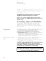
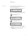
Struers ProntoPress-10 Manuel utilisateur
- Taper
- Manuel utilisateur

Manual No.: 15067003
Date of Release 11.01.2008
ProntoPress-10
Instruction Manual

ProntoPress-10
Instruction Manual
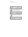
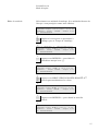
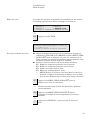
Table of Contents Page
User’s Guide ..............................................................1
Reference Guide.......................................................21
Quick Reference Card .............................................54
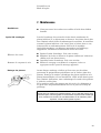
Always state Serial No and Voltage/frequency if you have technical questions or when ordering spare parts.
You will find the Serial No. and Voltage on the type plate of the machine itself. We may also need the Date
and Article No of the manual. This information is found on the front cover.
The following restrictions should be observed, as violation of the restrictions may cause cancellation of
Struers legal obligations:
Instruction Manuals: Struers Instruction Manual may only be used in connection with Struers equipment
covered by the Instruction Manual.
Service Manuals: Struers Service Manual may only be used by a trained technician authorised by Struers.
The Service Manual may only be used in connection with Struers equipment covered by the Service Manual.
Struers assumes no responsibility for errors in the manual text/illustrations. The information in this manual is
subject to changes without notice. The manual may mention accessories or parts not included in the present
version of the equipment.
The contents of this manual is the property of Struers. Reproduction of any part of this manual without the
written permission of Struers is not allowed.
All rights reserved. © Struers 2008.
Struers A/S
Pederstrupvej 84
DK-2750 Ballerup
Denmark
Telephone +45 44 600 800
Fax +45 44 600 801

ProntoPress-10
Instruction Manual
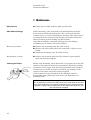
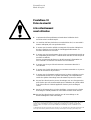
ProntoPress-10
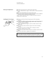
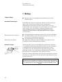
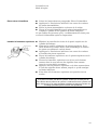
Safety Precaution Sheet
To be read carefully
before use
1. The operator should be fully aware of the use of the machine according
to the Instruction Manual.
2. The machine must be placed in a well ventilated room on a working
table with adequate height for handy operation.
3. Be sure that the actual voltage corresponds to the voltage stated on the
back of the machine and on the heating/cooling unit. The machine must
be earthed.
4. Be sure that the water connections are mounted correctly and without
leaks. The main water supply should be turned on when the machine is
in use.
Struers recommend that the mains water supply is shut off or
disconnected if the machine is to be left unattended.
5. Be sure that the outlet hose is attached to the water outlet system in a
safe way.
6. Be sure that the mounting unit is correctly assembled on the press
before starting the process.
7. Be sure that the top closure with upper ram is either correctly mounted
on the mounting cylinder or completely removed from the mounting
cylinder before starting the press.
8. Do not operate the mounting press with a higher force/pressure than
recommended for the actual cylinder diameter and resin in Struers
Application Guide for Hot Mounting.
9. Following a heating cycle, ensure the mounting cylinder is cooled for a
minimum of two minutes before opening.
10. Do not operate the machine whilst assembling or disassembling the
mounting unit.
The equipment is designed for use with consumables supplied by Struers. If subjected to misuse, improper
installation, alteration, neglect, accident or improper repair, Struers will accept no responsibility for
damage(s) to the user or the equipment.
Dismantling of any part of the equipment, during service or repair, should always be performed by a qualified
technician (electromechanical, electronic, mechanical, pneumatic, etc.).


ProntoPress-10
Instruction Manual
1
User’s Guide
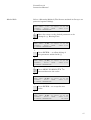
Table of Contents Page
1. Getting Started
Checking the Contents of Packing...................................................3
ProntoPress-10........................................................................... 3
Mounting Unit ...........................................................................3
Unpacking ProntoPress-10...............................................................3
Placing ProntoPress-10 ....................................................................3
Transport Screw Cap........................................................................3
Getting Acquainted with ProntoPress-10........................................ 4
Noise Level........................................................................................5
Supplying Power............................................................................... 5
Supplying Water...............................................................................5
Water Inlet.................................................................................5
Water Outlet..............................................................................5
Assembling the Mounting Unit........................................................ 6
Removing the Cover ..................................................................6
Installing the lower ram ...........................................................6
Installing the Mounting Unit....................................................6
Installing the Cover................................................................... 7
Installing the Dust Protection Ring ......................................... 7
Installing the Swivel Arm.........................................................7
Mounting of the Top Closure ....................................................7
Disassembling the Mounting Unit................................................... 7
Removing the Swivel Arm......................................................... 7
Descending the Lower Ram ......................................................7
Removing the Dust Protection Ring ......................................... 7
Removing the Cover ..................................................................8
Removing the Mounting Unit .......................................................... 8
Removing the lower ram ..................................................................8
Changing the Mounting Unit........................................................... 8
Software Settings.............................................................................. 9
Configuration Menu ..................................................................9
Setting the Language ..............................................................10
Setting the Cylinder Diameter ............................................... 11

ProntoPress-10
Instruction Manual
2
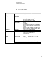
2. Basic Operations
Using the Controls.......................................................................... 12
Front Panel Controls of ProntoPress-10 ................................12
Groups of Keys......................................................................... 12
Acoustic Signals....................................................................... 12
Display .....................................................................................14
Main Switch............................................................................. 14
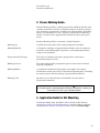
Mounting Method Options .............................................................15
Select a Mounting Method ...................................................... 15
Method Edit ............................................................................. 17
Placing the Specimen .....................................................................18
Pouring Resin over the Specimen...........................................18
Placing Two Specimens .................................................................. 19
Installing the Top Closure.............................................................. 19
Starting the Mounting Process ...................................................... 20
Display during the Mounting Process .................................... 20
Stopping the Mounting Process .....................................................20
Removing the Top Closure .............................................................20

ProntoPress-10
Instruction Manual
3
1. Getting Started
In the packing box you should find the following parts:
1 ProntoPress-10 machine
1 Swivel arm
1 Pressure hose
1 Filter gasket
1 Gasket
1 Reduction ring with gasket
2 Measuring spoons for mounting resin
1 Funnel
1 Air filter
1 Set of Instruction manuals
1 Mounting unit
1 Top closure with upper ram
1 Lower ram
1 Piston pin
1 Dust protection ring
1 Mould release agent (FASTI)
1 Scraper (PROAN)
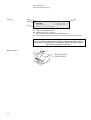
ProntoPress-10 is detached from the bottom of the packing case
by removing the four screws from below.
ProntoPress-10 should be placed on a steady table with an
adequate working height. The machine must be placed close to
the power supply, water mains and water outlet facilities. If water
recirculation is used, there must be room under the table for the
Recirculation Cooling Unit (TRECI).
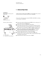
Carry out the following procedure before using the machine for
the first time Exchange the transport screw cap with the
enclosed air filter , to equalise the pressure in the hydraulic
system.
Checking the Contents of
Packing
ProntoPress-10
Mounting Unit
Unpacking ProntoPress-10
Placing ProntoPress-10
Transport Screw Cap
The transport screw cap is situated
underneath the cover for the mounting unit.

ProntoPress-10
Instruction Manual
4
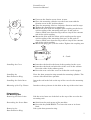
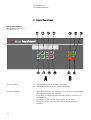
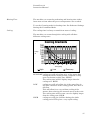
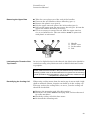
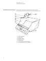
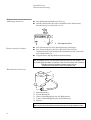
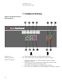
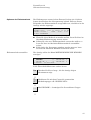
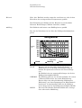
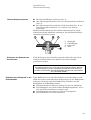
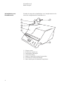
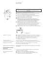
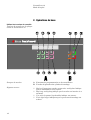
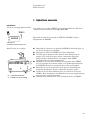
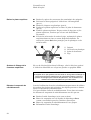
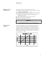
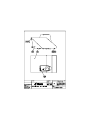
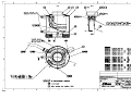
Take a moment to familiarise yourself with the location and
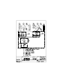
names of the ProntoPress-10 components.
Front panel
Top closure
Main switch
Mounting unit
Dust protection ring
Cover for mounting unit
Swivel arm for top closure
Getting Acquainted with
ProntoPress-10
➀
➅
➃
➄➁
➂
➆

ProntoPress-10
Instruction Manual
5
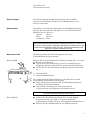
The noise level of the machine is 60 dB (A) measured when the
pump is running, at a distance of 1.0 m/39.4" from the machine.
ProntoPress-10 is factory mounted with an electric cable. Mount a
plug on the cable:
Brown: phase
Blue: neutral
Yellow/green: earth
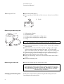
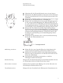
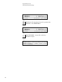
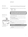
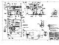
Water for cooling may be supplied from the water mains or a
Recirculation Cooling Unit.
Mount the pressure hose onto the water inlet tube (pos.1) on the
back of the machine:
Insert the filter gasket in the coupling nut with the flat side
against the pressure hose.
Tighten the coupling nut completely.
Water inlet
Water outlet tube
Mount the other end of the pressure hose on the water mains tap
for cold water:
Mount the reduction ring with gasket on the water mains tap,
if necessary.
Introduce the gasket and tighten the coupling nut completely.
Lead the water outlet tube (pos. 2) to the drain and be
absolutely sure to place the hose with a steady downward slope
and without any obstructions.
Attach the water outlet tube to the water outlet system.
Noise Level
Supplying Power
IMPORTANT
Check that the mains voltage corresponds to the voltage stated on the type
plate on the machine. Do not operate the machine before the transit screw
cap has been exchanged with the enclosed air filter.
Supplying Water
➀
➃
➄
➁
Water Inlet
IMPORTANT
Only connect to cold water
Water Outlet

ProntoPress-10
Instruction Manual
6
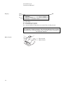
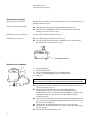
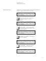
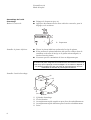
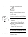
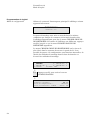
Loosen the catch (pos. 4).
Press gently on both sides of the cover, to release it, and lift it
up.
Place the lower ram on the top of the piston rod.
Turn the lower ram so that the holes in the axle journal on top
of the rod and ram line up, and insert the piston pin.
Make sure that the ends of the pin do not protrude.
Mounting cylinder
Fixation screw
Upper quick coupling for cooling water
Lower quick coupling for cooling water
Plug
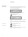
Assembling the Mounting Unit
Removing the Cover
➀
➃
➄
➁
Installing the lower ram
Important
The axle journal is part of the machine’s safety mechanism to protect
against damage to the machine. If it breaks, it must only be replaced with a
Struers replacement part or the safety mechanism may not function.
Installing the Mounting Unit
➀
➂
➃
➄
➁
IMPORTANT
Do not operate the machine whilst installing the mounting unit
Catch

ProntoPress-10
Instruction Manual
7
Unscrew the fixation screw about 10 mm.
Place the mounting cylinder over the lower ram with the
fixation screw in the position shown.
Turn the mounting unit in a clockwise direction until it stops.
Tighten the fixation screw completely.
Mount the tube with the straight quick coupling on the lower
quick coupling of the mounting unit (pos. 4) and push to
connect. Make sure that the ring comes to stop in the extreme
end of the quick coupling.
Mount the tube with the elbow quick coupling on the upper
quick coupling of the mounting unit (pos. 3) and push to
connect. Make sure that the ring comes to stop in the extreme
end of the quick coupling.
Mount the plug (pos. 5) in the socket. Tighten the coupling nut.
Introduce the barb in the front of the opening for the cover.
Introduce the barbs on both sides of the cover in the cabinet.
Press the sides of the cabinet gently.
Press the rear end of the cover in so that the catch engages.
Place the dust protection ring around the mounting cylinder. The
concave side should face upwards.
Insert the rod in the hole at the top of the cover for the mounting
unit.
Introduce the top closure in the hole at the top of the swivel arm.
Lift the swivel arm out of the hole at the top of the cover for the
mounting unit.
Switch on the main power of the machine.
Press the key RAM DOWN N to lower the ram to its lower
limit.
Lift up the dust protection ring.
➀
➃
➄
➁
Installing the Cover
Installing the
Dust Protection Ring
Installing the Swivel Arm
Mounting of the Top Closure
Disassembling
the Mounting Unit
Removing the Swivel Arm
Descending the Lower Ram
Removing the
Dust Protection Ring
Catch

ProntoPress-10
Instruction Manual
8
Press the catch (pos. 4).
Press gently on both sides of the cover, to release it, and lift it
up.
Mounting cylinder
Fixation screw
Upper quick coupling for cooling water
Lower quick coupling for cooling water
Plug
Disconnect the plug (pos. 5) in the socket. Loosen the coupling
nut and pull.
Disconnect the tube with elbow quick coupling on the upper
quick coupling on the mounting unit (pos. 3). Pull the ring.
Wait 5 seconds to allow the water to flow out of the cooling coil.
Disconnect the tube with straight quick coupling on the lower
quick coupling on the mounting unit (pos. 4). Pull the ring.
Unscrew the fixation screw about 10 mm.
Turn the mounting unit in an anti-clockwise direction until it
stops.
Lift the mounting unit.
Push the piston pin out of the lower ram.
Follow the instructions for Removing the Mounting Unit and
Installing the Mounting Unit.
Removing the Cover
➀
➃
➄
➁
Removing the Mounting Unit
➀
➂
➃
➄
➁
IMPORTANT
Do not operate the machine whilst removing the mounting unit
Removing the lower ram
Important
The axle journal is part of the machine’s safety mechanism to protect
against damage to the machine. Please see: Maintenance. If it breaks, it
must only be replaced with a Struers replacement part or the safety
mechanism may not function.
Changing the Mounting Unit
Catch

ProntoPress-10
Instruction Manual
9
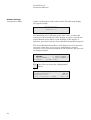
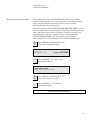
Switch on the power at the main switch. The following display
will appear briefly:
ProntoPress-10
Version: 2.0
The mounting press will start in the same state, as when the
voltage was last switched off. The display to appear could be the
Select Method Group Menu. If the heading in the display is
different, press Esc until the Select Method Group Menu appears.
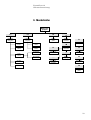
The Select Method Group Menu is the highest level in the menu
structure. From here you can go to configuration, manual
functions, select mounting methods in the database and open the
mounting methods.
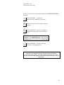
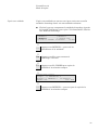
SELECT METHOD GROUP
1. STRUERS 2. GROUP NUMBER 2
3. GROUP NUMBER 3 4. GROUP NUMBER 4
F1:CONFIG. F3:MAN. FUNC.
D
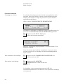
F1 Press F1 to activate the Configuration Menu.
D
CONFIGURATION
Cylinder Diameter: 50 mm
Temperature Unit: CELSIUS
Force or Pressure: FORCE Unit: kN
D
Software Settings
Configuration Menu

ProntoPress-10
Instruction Manual
10
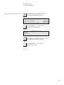
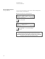
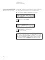
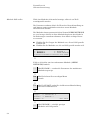
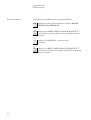
mO
mN
Press MENU UP/DOWN mO N to select the Language
parameter.
D
CONFIGURATION
Language: ENGLISH
Countdown mode: COUNT FROM START
D
e Press ENTER e to activate the
Language Options.
D
LANGUAGE
ENGLISH DEUTSCH
FRANCAIS JAPANESE
D
mO
mN
Press MENU UP/DOWN mO N to select the Language
you prefer.
D
e
Press ENTER e to accept a language.
The Configuration Menu now appears in the language
you have chosen.
Setting the Language
PLEASE NOTE
Voltage versions for 220 - 240 V:
include the languages English, French and German
Voltage versions for 100 - 120 V:
include the languages English, French and Japanese

ProntoPress-10
Instruction Manual
11
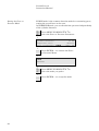
The cylinder diameter has to be set, in order to have the right
values of force or pressure. When a cylinder diameter is changed,
the database values of force or pressure in the methods will
automatically change to maintain the conditions in the mounting
cylinder.
Note: The counter, which warns the user to clean the rams after
200 mountings, will be reset when a new cylinder diameter is
selected. It is therefore important to clean away any old cured
resin beneath the lower ram when changing cylinder diameter.
Please see the instructions in the ‘Maintenance’ section.
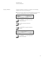
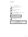
mO
mN
Press MENU UP/DOWN mO N to select the Cylinder
parameters.
D
CONFIGURATION
Cylinder Diameter: 50 mm
Temperature Unit: CELSIUS
Force or Pressure: FORCE Unit: kN
D
e Press ENTER e to activate the Cylinder Diameter
Menu.
D
CYLINDER DIAMETER
25 mm 30 mm 40 mm 50 mm
1 1/4" 1 1/2"
D
mO
mN
Press MENU UP/DOWN mO N to select the diameter
for the cylinder, which is mounted.
D
e Press ENTER e to accept the diameter.
D
Esc Press Esc to return to the Select Method Group Menu.
Setting the Temperature Unit, Force or Pressure Mode, Force
Unit, Pressure Unit and Countdown Mode: See the section
Advanced Operations.
Setting the Cylinder Diameter

ProntoPress-10
Instruction Manual
12
2. Basic Operations
A Programming and monitoring functions.
B Operation controls for the mounting cylinder.
Short Beep: when a key is pressed, a short beep indicates that
the command has been accepted.
Long Beep: a long beep indicates that the key is inactive at
that moment.
A sequence of four double beeps indicates an error.
Three long beeps: indicate that the mounting process is
finished.
Using the Controls
Front Panel Controls of
ProntoPress-10
Groups of Keys
A
coustic Signals

ProntoPress-10
Instruction Manual
13
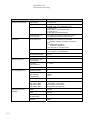
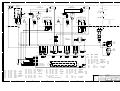
Pos. No. Key Function Pos. No. Key Function
MAIN
SWITCH
Turns the main power of the
machine on/off. The main switch
is located at the right hand side
of the cabinet.
2
FUNCTION
KEY
F2 Control for various purposes.
POWER
POWER Lights up when the main power
is on. 3
FUNCTION
KEY
F3 Control for various purposes.
START
s Starts the automatic mounting
process. 4
FUNCTION
KEY
F4 Control for various purposes.
STOP
o Stops the mounting process.
Stops upward or downward
movement of the lower ram.
5
MENU
UP
mO Moves the cursor/page up or
increases the parameter value.
RAM
UP
O Starts the upward movement of
the lower ram. The ram
automatically stops when the
upper limit is reached.
6
MENU
DOWN
mN Moves the cursor/page down or
decreases the parameter value.
RAM
DOWN
N Starts the downward movement
of the lower ram. The ram
automatically stops when the
lower limit is reached.
7
Esc Esc Leaves the present menu,
moves back one step or cancels
changes.
1
FUNCTION
KEY
F1 Control for various purposes. 8
ENTER
e Selects a menu or allows editing
of the marked parameters.

ProntoPress-10
Instruction Manual
14
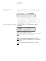
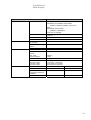
SELECT METHOD GROUP
1. STRUERS 2. GROUP NUMBER 2
3. GROUP NUMBER 3 4. GROUP NUMBER 4
F1:CONFIG. F3:MAN. FUNC.
A Heading.
B Flashing text. Cursor.
C Function key options.
D Arrow indicates that there are more lines in the picture.
Front panel
Main switch
Display
Please Note
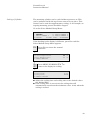
The examples of display screens in this Instruction Manual show a number
of possible texts. The actual display screen may differ from the examples in
the Instruction Manual.
➀
➅
➃
➄➁
➂
➆
Main Switch
B
C
D
A

ProntoPress-10
Instruction Manual
15
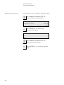
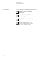
The mounting press will start in the same state, as when the
voltage was last switched off. If a mounting method was selected
at that time, this method will appear on the display.
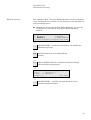
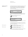
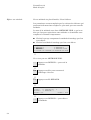
Grp: 2 Method: 3 Resin:MultiFast
HEAT: Time: 7:00 T: 180°C F: 20 kN
COOLING: Rate: HIGH Time: 3:00
F1:SELECT PREHEATING
If this mounting method can be used again, go to the section
Starting the Mounting Process.
If a new mounting method should be used, go to the section
Selecting a Mounting Method.
If some of the parameters have to be changed, go to the section
Method Edit.
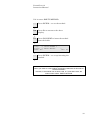
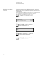
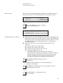
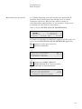
The display should show the Method Group Menu:
SELECT METHOD GROUP
1. STRUERS 2. GROUP NUMBER 2
3. GROUP NUMBER 3 4. GROUP NUMBER 4
F1:CONFIG. F3:MAN. FUNC.
If the heading in the display is different:
Esc Press Esc, until a display with the above heading
appears.
D
mO
mN Press MENU UP/DOWN O N until you reach the
desired Method Group, e.g. GROUP NUMBER 2.
D
e Press ENTER e, to accept the group.
D
Mounting Method Options
Select a Mounting Method

ProntoPress-10
Instruction Manual
16
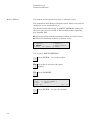
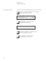
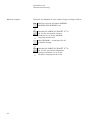
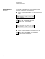
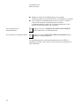
Group:GROUP NUMBER 2 SELECT METHOD
1. METHOD 1 2.METHOD 2
3. METHOD 3 4.EMPTY METHOD
F1:COPY F3:RESET F4:RENAME
D
mO
mN Press MENU UP/DOWN O N until you reach the
desired Method, e.g. METHOD 3.
D
Group:GROUP NUMBER 2 SELECT METHOD
1. METHOD 1 2.METHOD 2
3. METHOD 3 4.EMPTY METHOD
F1:COPY F3:RESET F4:RENAME
D
e Press ENTER e, to see the method.
D
Grp: 2 Method: 3 Resin:MultiFast
HEAT: Time: 7:00 T: 180°C F: 20 kN
COOLING: Rate: HIGH Time: 3:00
F1:SELECT PREHEATING
La page est en cours de chargement...
La page est en cours de chargement...
La page est en cours de chargement...
La page est en cours de chargement...
La page est en cours de chargement...
La page est en cours de chargement...
La page est en cours de chargement...
La page est en cours de chargement...
La page est en cours de chargement...
La page est en cours de chargement...
La page est en cours de chargement...
La page est en cours de chargement...
La page est en cours de chargement...
La page est en cours de chargement...
La page est en cours de chargement...
La page est en cours de chargement...
La page est en cours de chargement...
La page est en cours de chargement...
La page est en cours de chargement...
La page est en cours de chargement...
La page est en cours de chargement...
La page est en cours de chargement...
La page est en cours de chargement...
La page est en cours de chargement...
La page est en cours de chargement...
La page est en cours de chargement...
La page est en cours de chargement...
La page est en cours de chargement...
La page est en cours de chargement...
La page est en cours de chargement...
La page est en cours de chargement...
La page est en cours de chargement...
La page est en cours de chargement...
La page est en cours de chargement...
La page est en cours de chargement...
La page est en cours de chargement...
La page est en cours de chargement...
La page est en cours de chargement...
La page est en cours de chargement...
La page est en cours de chargement...
La page est en cours de chargement...
La page est en cours de chargement...
La page est en cours de chargement...
La page est en cours de chargement...
La page est en cours de chargement...
La page est en cours de chargement...
La page est en cours de chargement...
La page est en cours de chargement...
La page est en cours de chargement...
La page est en cours de chargement...
La page est en cours de chargement...
La page est en cours de chargement...
La page est en cours de chargement...
La page est en cours de chargement...
La page est en cours de chargement...
La page est en cours de chargement...
La page est en cours de chargement...
La page est en cours de chargement...
La page est en cours de chargement...
La page est en cours de chargement...
La page est en cours de chargement...
La page est en cours de chargement...
La page est en cours de chargement...
La page est en cours de chargement...
La page est en cours de chargement...
La page est en cours de chargement...
La page est en cours de chargement...
La page est en cours de chargement...
La page est en cours de chargement...
La page est en cours de chargement...
La page est en cours de chargement...
La page est en cours de chargement...
La page est en cours de chargement...
La page est en cours de chargement...
La page est en cours de chargement...
La page est en cours de chargement...
La page est en cours de chargement...
La page est en cours de chargement...
La page est en cours de chargement...
La page est en cours de chargement...
La page est en cours de chargement...
La page est en cours de chargement...
La page est en cours de chargement...
La page est en cours de chargement...
La page est en cours de chargement...
La page est en cours de chargement...
La page est en cours de chargement...
La page est en cours de chargement...
La page est en cours de chargement...
La page est en cours de chargement...
La page est en cours de chargement...
La page est en cours de chargement...
La page est en cours de chargement...
La page est en cours de chargement...
La page est en cours de chargement...
La page est en cours de chargement...
La page est en cours de chargement...
La page est en cours de chargement...
La page est en cours de chargement...
La page est en cours de chargement...
La page est en cours de chargement...
La page est en cours de chargement...
La page est en cours de chargement...
La page est en cours de chargement...
La page est en cours de chargement...
La page est en cours de chargement...
La page est en cours de chargement...
La page est en cours de chargement...
La page est en cours de chargement...
La page est en cours de chargement...
La page est en cours de chargement...
La page est en cours de chargement...
La page est en cours de chargement...
La page est en cours de chargement...
La page est en cours de chargement...
La page est en cours de chargement...
La page est en cours de chargement...
La page est en cours de chargement...
La page est en cours de chargement...
La page est en cours de chargement...
La page est en cours de chargement...
La page est en cours de chargement...
La page est en cours de chargement...
La page est en cours de chargement...
La page est en cours de chargement...
La page est en cours de chargement...
La page est en cours de chargement...
La page est en cours de chargement...
La page est en cours de chargement...
La page est en cours de chargement...
La page est en cours de chargement...
La page est en cours de chargement...
La page est en cours de chargement...
La page est en cours de chargement...
La page est en cours de chargement...
La page est en cours de chargement...
La page est en cours de chargement...
La page est en cours de chargement...
La page est en cours de chargement...
La page est en cours de chargement...
La page est en cours de chargement...
La page est en cours de chargement...
La page est en cours de chargement...
La page est en cours de chargement...
La page est en cours de chargement...
La page est en cours de chargement...
La page est en cours de chargement...
La page est en cours de chargement...
La page est en cours de chargement...
La page est en cours de chargement...
La page est en cours de chargement...
La page est en cours de chargement...
La page est en cours de chargement...
La page est en cours de chargement...
La page est en cours de chargement...
La page est en cours de chargement...
La page est en cours de chargement...
La page est en cours de chargement...
La page est en cours de chargement...
La page est en cours de chargement...
La page est en cours de chargement...
La page est en cours de chargement...
La page est en cours de chargement...
La page est en cours de chargement...
La page est en cours de chargement...
La page est en cours de chargement...
La page est en cours de chargement...
La page est en cours de chargement...
La page est en cours de chargement...
La page est en cours de chargement...
La page est en cours de chargement...
La page est en cours de chargement...
La page est en cours de chargement...
La page est en cours de chargement...
La page est en cours de chargement...
La page est en cours de chargement...
La page est en cours de chargement...
La page est en cours de chargement...
La page est en cours de chargement...
La page est en cours de chargement...
La page est en cours de chargement...
La page est en cours de chargement...
La page est en cours de chargement...
La page est en cours de chargement...
La page est en cours de chargement...
La page est en cours de chargement...
La page est en cours de chargement...
-
 1
1
-
 2
2
-
 3
3
-
 4
4
-
 5
5
-
 6
6
-
 7
7
-
 8
8
-
 9
9
-
 10
10
-
 11
11
-
 12
12
-
 13
13
-
 14
14
-
 15
15
-
 16
16
-
 17
17
-
 18
18
-
 19
19
-
 20
20
-
 21
21
-
 22
22
-
 23
23
-
 24
24
-
 25
25
-
 26
26
-
 27
27
-
 28
28
-
 29
29
-
 30
30
-
 31
31
-
 32
32
-
 33
33
-
 34
34
-
 35
35
-
 36
36
-
 37
37
-
 38
38
-
 39
39
-
 40
40
-
 41
41
-
 42
42
-
 43
43
-
 44
44
-
 45
45
-
 46
46
-
 47
47
-
 48
48
-
 49
49
-
 50
50
-
 51
51
-
 52
52
-
 53
53
-
 54
54
-
 55
55
-
 56
56
-
 57
57
-
 58
58
-
 59
59
-
 60
60
-
 61
61
-
 62
62
-
 63
63
-
 64
64
-
 65
65
-
 66
66
-
 67
67
-
 68
68
-
 69
69
-
 70
70
-
 71
71
-
 72
72
-
 73
73
-
 74
74
-
 75
75
-
 76
76
-
 77
77
-
 78
78
-
 79
79
-
 80
80
-
 81
81
-
 82
82
-
 83
83
-
 84
84
-
 85
85
-
 86
86
-
 87
87
-
 88
88
-
 89
89
-
 90
90
-
 91
91
-
 92
92
-
 93
93
-
 94
94
-
 95
95
-
 96
96
-
 97
97
-
 98
98
-
 99
99
-
 100
100
-
 101
101
-
 102
102
-
 103
103
-
 104
104
-
 105
105
-
 106
106
-
 107
107
-
 108
108
-
 109
109
-
 110
110
-
 111
111
-
 112
112
-
 113
113
-
 114
114
-
 115
115
-
 116
116
-
 117
117
-
 118
118
-
 119
119
-
 120
120
-
 121
121
-
 122
122
-
 123
123
-
 124
124
-
 125
125
-
 126
126
-
 127
127
-
 128
128
-
 129
129
-
 130
130
-
 131
131
-
 132
132
-
 133
133
-
 134
134
-
 135
135
-
 136
136
-
 137
137
-
 138
138
-
 139
139
-
 140
140
-
 141
141
-
 142
142
-
 143
143
-
 144
144
-
 145
145
-
 146
146
-
 147
147
-
 148
148
-
 149
149
-
 150
150
-
 151
151
-
 152
152
-
 153
153
-
 154
154
-
 155
155
-
 156
156
-
 157
157
-
 158
158
-
 159
159
-
 160
160
-
 161
161
-
 162
162
-
 163
163
-
 164
164
-
 165
165
-
 166
166
-
 167
167
-
 168
168
-
 169
169
-
 170
170
-
 171
171
-
 172
172
-
 173
173
-
 174
174
-
 175
175
-
 176
176
-
 177
177
-
 178
178
-
 179
179
-
 180
180
-
 181
181
-
 182
182
-
 183
183
-
 184
184
-
 185
185
-
 186
186
-
 187
187
-
 188
188
-
 189
189
-
 190
190
-
 191
191
-
 192
192
-
 193
193
-
 194
194
-
 195
195
-
 196
196
-
 197
197
-
 198
198
-
 199
199
-
 200
200
-
 201
201
-
 202
202
-
 203
203
-
 204
204
-
 205
205
-
 206
206
-
 207
207


Struers ProntoPress-10 Manuel utilisateur
- Taper
- Manuel utilisateur
dans d''autres langues
- English: Struers ProntoPress-10 User manual
- Deutsch: Struers ProntoPress-10 Benutzerhandbuch
Documents connexes
-
 Struers RotoPol-11 Manuel utilisateur
-
 Struers ProntoPress-2 Manuel utilisateur
-
 Struers Prepamatic-2 Manuel utilisateur
-
 Struers RotoPol-21 Manuel utilisateur
-
 Struers Accutom-50 Manuel utilisateur
-
 Struers Abramin Manuel utilisateur
-
 Struers ViaFix Manuel utilisateur
-
 Struers LaboForce-3 Manuel utilisateur
-
 Struers Unitom-50 Manuel utilisateur
-
 Struers Unitom-5 Manuel utilisateur


