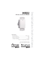
Legrand MRD2 Wireless Incandescent Dimmer Guide d'installation
- Catégorie
- Gradateurs
- Taper
- Guide d'installation

MRD2
Wireless Incandescent Dimmer
Specifications
Operating Voltage ................................................120VAC, 60Hz
Maximum Load Rating ..................................................... 600W
Minimum Load Required ................................................... 60W
Load Type Compatibility ..............................................60-600W
Incandescent (tungsten/quartz halogen)
U.S. Patent 6,175,220. Other utility,
design, and foreign patents pending.
Installation Instructions

UNIT DESCRIPTION
The Miro™ MRD2 Wireless Incandescent Dimmer is mounted inside a wall box
and framed by an architectural screwless Miro wall plate (required and sold
separately).
Miro wireless devices use radio signals to communicate with each other to
control lighting and other types of electric loads in selected areas. Miro wireless
devices use the 900MHz band for high-speed control communication. Using
the Watt Stopper’s own “frequency-agile” Top Dog™ technology, Miro wireless
devices avoid interference with other 900MHz devices, such as cordless phones
and baby monitors.
Load Types
Use the MRD2 incandescent dimmer for these load types (60-600W at 120V):
• Incandescent & quartz halogen lamps
Do not mix different load types on the same dimmer.
Do not use with diode equipped (some types of energy saving) lamps.
Do not use for motors.
For dimmable, 2-wire fl uorescent and compact fl uorescent fi xtures, magnetic or
electronic low voltage, neon or cold cathode fi xtures or diode equipped lamps,
use the Miro MRD4 wireless universal dimmer, or the Miro MCD267 universal
dimmer.
Derating
When more than one dimmer is installed in a multi-gang box, it is necessary to
reduce the maximum load on each dimmer:
• For a dimmer in either end position of a multi-gang box, reduce its maximum
load by 100W.
• For a dimmer in a central position of a multi-gang box, reduce its maximum
load by 200W.
CAUTION
To reduce the risk of
overheating and possible
damage to other equipment,
do not install to control
a receptacle, a motor-
operated appliance, or a
fl uorescent lighting fi xture.
CAUTION
Afi n de réduire le risque de
surchauffe et la possibilité
d’endommager d’autres
matériels, ne pas installer
pour commander une prise,
un appareil à moteur, ou
une lampe fl uorescente.

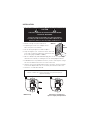
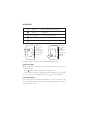
INSTALLATION
1. Disconnect power to circuit by turning circuit breaker OFF before installation.
2. Remove existing cover plate and switch.
3. Temporarily attach the steel subplate for the
Miro cover plate to the wall box.
4. Pull the wiring through the new Miro subplate.
5. Strip existing wires 1/2”. If two wires will be connected
to the same terminal on a Miro device, both wires must
be the same gauge (12AWG or 14AWG).
6. Wire the LINE (black), LOAD and GND supply wires to the correspondingly
marked screw terminals, according to one of the wiring diagrams below.
7. If NEUTRAL wires are provided to the fi xture, connect them together using a
wire nut. The dimmer does not use a neutral connection.
8. Using the instructions provided with the Miro cover plate, attach the dimmer
to the metal subplate and to the electrical box, then attach the Miro cover.
9. Switch the circuit breaker back ON.
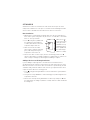
LOAD
LINE
GND
LOAD
LINE
GND
MRD2 wiring Switch-leg circuit wiring, to
replace a single-pole light switch
INSTALL IN COMPLIANCE WITH ALL APPLICABLE CODES & STANDARDS.
Failure to follow these instructions may cause personal injury or
equipment damage.
Steel
subplate
Wall box
CAUTION
TURN THE POWER OFF AT THE CIRCUIT BREAKER BEFORE
INSTALLING THE DIMMER.
Install only using a UL Listed Miro cover plate and subplate
assembly. If you do not have the proper Miro subplate for your
application, obtain one from any supplier of Miro devices.

SET HOUSE ID
All Miro wireless devices installed in the same home must acquire the same
unique House ID before use. This process is known as house binding. Each Miro
wireless device is bound to all other Miro wireless devices in the house.
New Installation
1. With all devices installed and energized, make sure that every Miro wireless
device LED is yellow. If any LED is off, be sure the circuit breaker is on and the
device is correctly installed.
2. Press
on any device paddle until
the LED fl ashes yellow (about 2
seconds). This indicates that it has
acquired a unique House ID.
3. Make sure that all other Miro
wireless device LEDs are fl ashing
green, indicating that they have
acquired the same House ID.
4. Return to the device used in step 2, which is still fl ashing yellow. Press
until the LED changes to solid green (about 2 seconds). All device LEDs in the
House change to solid green, indicating house binding is complete.
Adding a Device to an Existing Installation
If you’re adding or replacing a device in a Miro wireless installation that is
already operating, the new device must acquire the same House ID as the other
Miro wireless devices in the house. After the new device is powered up, the LED
should be solid yellow. This indicates that it has not yet acquired a House ID. To
acquire the House ID for the existing system:
1. Press
on any previously bound device until the LED fl ashes yellow (about 2
seconds).
2. Verify that the newly added device LED is fl ashing green, indicating that it has
acquired the House ID.
3. Return to the same previously bound device used in step 1 and press until
the LED changes to solid green (about 2 seconds). All device LEDs should now
be solid green.
When you see
in the instructions,
fi rmly press and
hold both the top
and bottom of the
device paddleuntil
the LED changes
(about 2 seconds).

OPERATION
Tap once Fade the load to its last-used level
Tap twice Full bright
—
— Press and hold Increase the present level
Tap once Fade the load to OFF
—
— Press and hold Decrease the present level
The dimmer may feel warm to the touch during normal operation.
Replacing Lamps
When a lamp must be replaced, use the Air Gap Isolation feature for safety. To
activate the feature:
Press
FIRMLY, so that the paddle clicks and latches in.
Make sure the status LED is extinguished, indicating that it’s safe to relamp.
To release and return to normal operation, press
. The status LED lights.
Power Fail Memory
After a power failure, all Miro devices automatically return to the state that they
were in immediately prior to loss of power. All confi guration and scene control
information is preserved.
When you
see
in the
instructions,
touch the top
of the paddle
as directed.
When you
see
in the
instructions,
touch the
bottom of the
paddle as
directed.

Advanced Operation
Groups
Use a Miro wireless incandescent dimmer in conjunction with one or more Miro
MRD8 Wireless Multilocation Controllers to control one lighting circuit from
multiple locations. Binding the MRD2 and MRD8 devices together in the same
Group enables them to work in exactly the same way, from any of the control
locations.
You can include other Miro wireless devices in the Group. Just remember that
all devices in the Group operate when one member operates. If you increase the
brightness on one circuit in the Group, all circuits will increase brightness.
Set the House ID (see Set House ID) before setting up Groups.
1. Go to any device that you want to include in the Group. Press
. The device
LED fl ashes yellow, and all other devices in the House fl ash green.*
You now have 5 minutes to complete this process.
2. To include or exclude a device in the Group press
on the device until the
LED changes color. Yellow fl ashing LED = Included in the Group
Green fl ashing LED = NOT included in the Group
If you get to a device and it is NOT fl ashing, the 5 minute binding process
timer may have expired. Go back to step 1 and repeat.
3. Return to the device used in step 1 and press
to terminate Group binding.
All LEDs revert to solid green. Now, all the devices in the Group control their
load circuit in exactly the same manner.
* Adding a Dimmer to a Group in an Existing System
1. Go to a device that is in the Group where you want to add the dimmer.
Press
. The device LED and all members of the Group fl ash yellow. The new
dimmer fl ashes green.
2. Press on the new dimmer until it’s LED fl ashes yellow.
3. Return to the device used in step 1 and press
. All LEDs are solid green.
Scene Control
The Miro wireless incandescent dimmer may be easily incorporated into room
and whole house preset scenes. The Miro Installation Guide provides more
information about confi guring scenes and presets.
Instructions for installation and use are included with the relevant Miro wireless
room and whole house control devices. Application support information and the
Miro Installation Guide is available online.

CLEANING
Clean only using a cloth dampened with water and a little mild detergent.
Use of solvents or hydrocarbon-based cleaners may cause permanent damage.
TROUBLESHOOTING
During Set House ID, the LED is not flashing on some wireless Miro
devices.
• If LED is solid green before initiating house ID binding:
The device already has another house ID. Reset it to the factory default so
that it can be bound to the desired house ID. Resetting to factory defaults is
described in the “I need to start over” issue.
• If LED is solid yellow after initiating house ID binding:
The device may be out of range of the initiating device. Add a MRR2 Miro
Wireless Repeater to boost signal range.
I made a configuration mistake. I need to start over.
You can reset any Miro wireless device to factory default settings by pressing
and holding
until the LED changes to solid yellow (approximately 10
seconds). During the process, the LED fl ashes yellow and when complete, it
changes to solid yellow. The device can then be reconfi gured, exactly like any
new device (see the Set House ID section).
The dimmer does not work and the status LED is flashing red
• at 2Hz (10 times in 5 seconds):
The dimmer has detected an overload condition and has shut down.
To clear the fault condition, tap and wait for the LED to turn green.
Disconnect loads in excess of rated load and try again.
• at 3Hz (15 times in 5 seconds):
The dimmer has detected a short-circuit condition and has shut down.
To clear the fault condition, tap and wait for the LED to turn green.
Remove power, rectify the short-circuit condition, restore power, and try again.

FCC NOTICE
This equipment has been tested and found to comply with the limits for a Class
B digital device, pursuant to part 15 of the FCC Rules. These limits are designed
to provide reasonable protection against harmful interference in a residential
installation. This equipment generates, uses and can radiate radio frequency
energy and, if not installed and used in accordance with the instructions, may
cause harmful interference to radio communications. However, there is no
guarantee that interference will not occur in a particular installation. If this
equipment does cause harmful interference to radio or television reception,
which can be determined by turning the equipment off and on, the user is
encouraged to try to correct the interference by one or more of the following
measures:
• Reorient or relocate the receiving antenna.
• Increase the separation between the equipment and receiver.
• Connect the equipment into an outlet on a circuit different from that to which
the receiver is connected.
• Consult the dealer or an experienced radio/TV technician for help.
Caution: Any changes or modifi cations to this device not explicitly approved by
manufacturer could void your authority to operate this equipment.
Warranty Information
Manufacturer warranties its products to be free of defects in materials and
workmanship for a period of five (5) years. There are no obligations or liabilities
on the part of manufacturer for consequential damages arising out of, or
in connection with, the use or performance of this product or other indirect
damages with respect to loss of property, revenue or profit, or cost of removal,
installation or reinstallation.
03875r2 9/2007
2800 De La Cruz Blvd.
Santa Clara, CA 95050
Phone: 800.879.8585
www.wattstopper.com
Please
Recycle
1061 South 800 East
Orem, UT 84057
Phone: 800.555.9891
www.vantagecontrols.com
Watt Stopper Customers contact: Vantage Customers contact:
-
 1
1
-
 2
2
-
 3
3
-
 4
4
-
 5
5
-
 6
6
-
 7
7
-
 8
8


Legrand MRD2 Wireless Incandescent Dimmer Guide d'installation
- Catégorie
- Gradateurs
- Taper
- Guide d'installation
