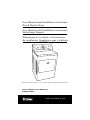
Haier RDE User Manual and Installation Instructions
- Catégorie
- Sèche-linge électriques
- Taper
- User Manual and Installation Instructions
Ce manuel convient également à

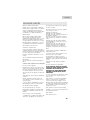
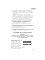
User Manual and Installation Instructions
Gas & Electric Dryer
User Manual and Installation Instructions
Sèche-linge Genesis
Manual para el usuario e instrucciones
de instalación. Secadora a gas y eléctrica
Model #/ Modéle #/ Para Modelo de #
RDE/RDG 350AW
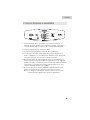
Quality
Ƶ
Innovation
Ƶ
Style
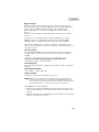
(Picture for illustration purposes only. Actual model may vary per model purchased.)
Air Fluff
120 min
90 min
60 min
30 min
Timed Dry
Automatic
Super Capacity

1
English
PAGE
IMPORTANT SAFETY INSTRUCTIONS.......................................2-4
INSTALLATION INSTRUCTIONS..............................................5-17
Tools and Materials Required............................................................ 5
Electrical Requirements ..................................................................... 5
Unpacking Your Dryer ..................................................................... 6
Exhaust System Requirements ........................................................... 7
Gas Supply Requirements ................................................................ 9
Location of Your Dryer ...................................................................10
Manufactured (Mobile) Home Instruction .........................................11
Electrical Installation ......................................................................12
3-Wire Cord Connections ..............................................................13
4-Wire Cord Connections ..............................................................14
Gas Connections ..........................................................................15
Replacement Parts ......................................................................... 17
OPERATING INSTRUCTIONS ............................................... 18-24
Understanding the Control Panel......................................................18
Preparations before Drying .............................................................19
Load clothes into Dryer...................................................................20
Auto Dry Cycle..............................................................................21
Timed Dry Cycle ............................................................................22
Other Features ..............................................................................23
Normal Operating Sounds..............................................................24
Tips..............................................................................................24
CARE AND CLEANING GUIDE
.......................................................24
TROUBLESHOOTING.................................................................. 25
LIMITED WARRANTY .................................................................26
TABLE OF CONTENTS

2
English
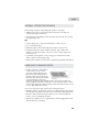
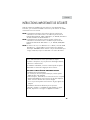
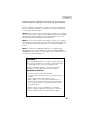
IMPORTANT SAFETY INSTRUCTIONS
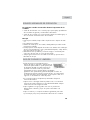
Before beginning installation, carefully read these instructions. This will simplify
the installation and ensure the dryer is installed correctly and safely.
NOTE: The electrical service to the dryer must conform with local codes and
ordinances and the latest edition of the National Electrical Code, ANSI/
NFPA 70 or in Canada, CSA C22.1 Canadian Electrical Code Part 1.
NOTE: The gas service to the dryer must conform with local codes and
ordinances and the latest edition of the National Fuel Gas Code, ANSI
Z223.1 or in Canada, CAN/CGA B149.1.
NOTE: The dryer is designed under ANSI Z21.5.1 or ANSI/UL 2158 - CAN/
CSA C22.2 No. 112-97 (latest editions) for HOME USE ONLY. This
dryer is not recommended for commercial application such as restaurants,
beauty salons, etc.
WARNING
For your safety the information in this manual must be
followed to minimize the risk of fire or explosion or to
prevent property damage, personal injury or loss
of life.
Combustible materials, gasoline, and other flammable vapors and
liquids must not be stored near the dryer.
WHAT TO DO IF YOU SMELL GAS
1. Do not try to light any appliance
2. Do not touch any electrical switch. Do not use any phone in
your building.
3. Clear the room, building, or area of all occupants.
4. Immediately call your gas supplier from a neighbor’s phone.
Follow the gas supplier’s instructions.
5. If you cannot reach your gas supplier, call the Fire Department.
Installations must be performed by a qualified or licensed
contractor, plumber, or gasfitter qualified or licensed by the state,
province, or region where this appliance is being installed.

English
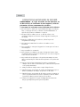
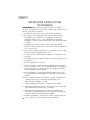
IMPORTANT SAFETY
INSTRUCTIONS
WARNING - To reduce the risk of fire, electric shock, or
injury to persons when using your appliance, follow the
basic precautions, including the following:
1. Read all of the instructions before using this appliance.
2. Don’t dry articles that have been previously cleaned in, washed in,
soaked in, or spotted with gasoline, dry clean solvents or other
flammable explosive sub stains as they give off vapors which could
ignite or explode.
3. Do not allow children to play on or in the appliance. Close
supervision of children is necessary when the appliance is used near
children.
4. Before the appliance is removed from service or discarded, remove
the door to the drying compartment.
5. Do not reach into the appliance if the drum is moving.
6. Do not install or store this appliance where it will be exposed to
water and/or to the weather.
7. Do not tamper with controls.
8. Do not repair or replace any part of the appliance or attempt any
servicing unless specifically recommended in the user-repair
instructions that you understand and have skills to carry out.
9. Do not use fabric softeners or products to eliminate static unless
recommended by the manufacturers of the fabric softener or
product.
10. Do not use heat to dry articles or products to eliminate static unless
recommended by the manufacturers of the fabric softener or
product.
11. Clean lint screen before or after each load.
12. Keep area around the exhaust opening and adjacent surrounding
areas free from the accumulation of lint, dust and dirt.
13. Keep the dryer area clear and free from items that would obstruct
the flow of combustion and ventilation air through the louvered panel
located on the rear of the dryer.
14. The interior of the appliance and the exhaust duct should be cleaned
periodically by qualified service personnel.
3

English
4
Thank you for using our Haier
product. This easy-to-use manual
will guide you in getting the best
use of your dryer.
Remember to record the model and
serial number. They are on a label
in back of the dryer.
Model number
Serial number
Date of purchase
Staple your receipt to your manual.
You will need it to obtain warranty service.
15. Do not place items exposed to cooking oils in your dryer. Items
contaminated with cooking oil may contribute to a chemical reaction
than could cause a load to catch fire.
16. If material has been used with any flammable liquids or solids, it
should not used in the dryer until all terraces of flammable liquids
and its fumes have been removed.
17. This dryer must be properly installed in accordance with the
installation instructions before it is used. See grounding instructions in
the installations sections.
18. Proper grounding must be ensured to reduce the risk of electric shock
and fire. Check with a qualified electrician or service personnel if you
are in doubt as to whether the dryer is properly grounded.
19. Use the dryer only for its intended purpose: drying clothes.
20. Always disconnect dryer from electrical supply before attempting any
service. Disconnect power cord by grasping the plug, not the cord.
21. Replace worn power cord and/or loose plugs.
22. To reduce the risk of electric shock or fire, do not use extension cords
or adapters to connect dryer electrical power source.
SAVE THESE
INSTRUCTIONS
DANGER
Risk of child entrapment. Before you throw away your old dryer,
take off the door so that children may not get trapped inside.

5
ELECTRICAL REQUIREMENTS
Electric Dryer:
(RDE350AW)
Circuit
Individual 30 Amp branch circuit fused with 30 Amp time-delay fuses or circuit
breakers. Use seperately fused circuits for washers and dryers, and DO NOT
operate a washer and dryer on the same circuit.
Power Supply
3 or 4 wire, 120/240 Volt, 1 Phase, 60Hz, AC
(Canada - 120/240 Volt, 1 Phase, 60 Hz, AC)
Power Supply Cord Kit
(Not supplied when sold in US. Must be purchased to meet local electrical
codes.) The dryer MUST employ a 3-conductor power supply cord NEMA
10-30 Type SRDT rated at 240 Volt AC minimum, 30 Amp, with 3 open end
INSTALLATION INSTRUCTIONS
English
Risk of Fire:
SAVE THESE INSTRUCTIONS
Tools and materials required
• Phillips-Head and flathead screwdrivers
• Channel-lock adjustable pilers
• 1/2-inch open-end wrench
• Carpenter’s level
• Measuring tape (12ft. min.)
• Duct tape
• Pipe thread sealer (Gas)
• Rigid or flexible metal 4 inch
(102cm) duct
• Vent hood
Safety Warning:
1. Before starting installation, make sure that the gas shut off valve is in the
off position.
2. All old gas connectors and gas piping should be discarded.
WARNING
1.Clothes dryer installation must be performed by a qualified installer.
2.Install the clothes dryer according to the manufacturer’s instructions and local
codes.
3.Do not install a clothes dryer with flexible plastic venting materials.
If flexible metal (foil type) duct is installed,it must be of a specific type identified by
the appliance manufacturer as suitable for use with clothes dryers. Flexible venting
materials are known to collapse, be easily crushed,and trap lint.These conditions
will obstruct clothes dryer airflow and increase the risk of fire.
4.To reduce the risk of severe injury or death, follow all installation instructions.

English
6
spade lug connectors with upturned ends or closed loop connectors and marked
for use with clothes dryers.
(When sold in Canada - 4-wire power supply cord provided and
attached on dryer)
Dryers being installed in a manufactured (mobile) home MUST employ a
4-wire power supply cord NEMA 14-30 type SRDT or ST (as required) rated
to 240 Volt AC minimum, 30 Amp, with 4 open-end spade lug connectors
with upturned ends or closed loop connectors and marked for use with clothes
dryers. See Electrical Connections for more information on a 4-wire system.
Outlet Receptacle
NEMA 10-30R receptacle should be located so the power supply cord is
accessible when the dryer is in the installed position. (Canada - NEMA 14-30R
receptacle)
ELECTRICAL REQUIREMENTS
Gas Dryer:
(RDG350AW)
Circuit
Individual 15 Amp branch circuit fused with 15-Amp maximum time delay fuse
or circuit breakers.
Power Supply
3 wire, 120 Volt, 1 Phase, 60Hz, AC
Power Supply Cord
The dryer is equipped with a 120 Volt 3-wire power supply cord.
Note: This dryer is equipped with a three-prong grounding plug for your
protection against shock hazard and should be plugged into a properly
grounded three-prong receptacle. Do not under any circumstance cut or
remove grounding prong from plug.
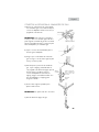
Unpacking Your Dryer
1. Remove all packaging material. This includes the foam base and all adhesive
tape holding the dryer accessories inside and outside.
2. Inspect and remove any remains of packaging, tape or printed materials
before using the dryer.

The following are specific requirements for
proper and safe operation of your dryer. Failure
to follow these instructions can create excessive
drying times and fire hazards.
1. Do not use plastic flexible duct to exhaust the dryer. Excessive lint can build up
inside exhaust system and create a fire hazard and restrict air flow. Restricted
air flow will increase drying time. If your present system is made up of plastic
duct or metal foil duct, replace it with a rigid or flexible metal duct. Ensure
present duct is free of any lint prior to installing dryer duct.
2. The dryer must not be exhausted into any gas vent, chimney, wall, ceiling or
any concealed space of a building. The dryer exhaust system MUST be
exhausted to the outdoors. If the dryer is not exhausted outdoors, some
fine lint will be expelled into the laundry area. An accumulation of lint in any
area of the home can create a health and fire hazard.
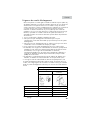
3. Exceeding the length of duct pipe or number of elbows allowed in the
“Maximum Length” chart can cause an accumulation of lint in the exhaust
system. Plugging the system could create a fire hazard, as well as increase
drying times.
4. Do not screen the exhaust ends of the vent system. Lint can become caught in
the screen, increasing drying time. Use an approved vent hood to terminate the
duct outdoors, and seal all joints with duct tape.
5. All male duct pipe fittings must be installed downstream with the flow of air.
6. Exhaust duct must not be connected or secured with screws or other fastening
devices which extend into the interior of the duct.
7. Do not allow combustible material (clothing, draperies/curtains, paper, etc.) to
come in contact with exhaust system.
Explosion hazard:
Do not install the dryer where gasoline or other flammables are kept or
stored. If the dryer is installed in a garage, it must be a minimum of 18
inches (45.7cm) above the floor. Failure to do so can result in death,
explosion, fire or burns.
Exhaust Requirements:
Use only 4 inch (10.2cm) diameter (minimum) rigid of flexible metal duct and
approved vent hood which has a swing-out damper hat open when the dryer is
in operation. When the dryer stops, the dampers automatically close to prevent
drafts and the entrance of insects and rodents. To avoid restricting the outlet,
WARNING
EXHAUST SYSTEM REQUIREMENTS
English
7

maintain a minimum of 12 inches (30.5cm) clearance between the vent hood
and the ground or any other obstruction. The vent flap should be able to move
freely, although vertical orientation of the exhaust system is acceptable. Certain
extenuating circumstances could affect the performance of the dryer:
1. Only rigid or flexible metal duct work should be used.
2. Venting vertically through a roof may expose the exhaust system to down
drafts causing an increase in vent restriction.
3. Running the exhaust system through an uninsulatedarea may cause
condensation and faster accumulation of lint.
4. Compression of crimping of the exhaust system will cause an increase in
vent restriction.
The exhaust system should be inspected and cleaned a minimum of every 12
months with normal usage. The more the dryer is used the more often you
should check the exhaust system and vent hood for proper operation.
English
8
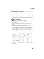
RECOMMENDED MAXIMUMM
Exhaust Hood Types
Recommended Use only for short
run installations
No. of 90º
elbows
Rigid Metal Rigid Metal
0 90 ft. 60 ft.
1 60 ft. 45 ft.
2 45 ft. 35 ft.
3 35 ft. 25 ft.
5. In Canada, that only those foil-type flexible ducts, if any, specifically identified
for use with the appliance by the manufacturer shall be used. In the United
States, that only those foil-type flexible ducts, if any, specifically identified for
use with the appliance by the manufacturer and that comply with the UL
Outline for Clothes Dryer Transition Duct, Subject 2158A (2006), shall be used.
6. In Canada, that the exhaust duct shall be 102 mm in diameter. In the United
States, the required exhaust duct diameter;
7. The total length of flexible metal duct shall not exceed 2.4 m.
Note: Exhausting refers to removal of moist air from the drying compartment.

GAS SUPPLY REQUIREMENTS
English
9
WARNING
Replace copper connecting pipe that is not plastic-
coated. Stainless steel or plastic-coated brass MUST
be used.
1.Installation MUST conform with local codes. In the absence of local codes,
installation must conform with the National Fuel Gas Code, ANSI Z223.1 (latest
edition) or in Canada, the current CAN/CGA B149.1
2. The gas supply line should be 1/2 inch (1.27cm) pipe.
3. If codes allow, flexible metal tubing may be used to connect your dryer to the
gas supply line. The tubing MUST be constructed of stainless steel or plastic-
coated brass.
4. The gas supply line MUST have an individual manual shutoff valve installed
within 6 feet (183cm) of the dryer in accordance with the National Fuel Gas
Code, ANSI Z223.1/NFPA 54.
In Canada, an individual manual shut-off valve MUST be installed in
accordance with the B149.1, Natural Gas and Propane Installation Code.
5. A 1/8 inch (0.32cm) N.P.T. plugged tapping, accessible for test gauge
connection, MUST be installed immediately upstream of the gas supply
connection to the dryer.
6. The dryer MUST be disconnected from the gas supply piping system during
any pressure testing of the gas supply piping system at test pressures in excess
of 1/2 psig (3.45kPa).
7. The dryer MUST be isolated from the gas supply piping system during any
pressure testing of the gas supply piping system at test pressures equal to or
less than 1/2 psig (3.45 kPa).

English
10
Do Not Install Your Dryer:
1. In an area exposed to dripping water or outside weather conditions.
2. In an area where it will come in contact with curtains, thick carpet, or anything
that will obstruct the flow of combustion and ventilation air.
3. On carpet, floor must be solid with a maximum slope of 1inch (2.54 cm). Any
floor unevenness should be corrected with leveling legs located on the bottom
of the dryer.
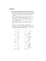
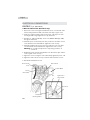
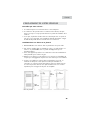
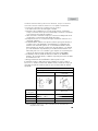
Installation in Alcove or Closet:
1. DO NOT install your dryer in a closet with a solid door.
2. A dryer installed in a bedroom, bathroom, alcove or closet MUST be
exhausted outdoors.
3. No other fuel burning appliance shall be installed in the same closet as the
gas dryer.
4. Refer to the images on this page to ensure the installation provides the
minimum amount of clearance required for ventilation.
5. When installing the dryer in a closet with a door, a minimum of 120 square
inches (774.2 square cm) of ventilation in the door is required. Openings must
be equally divided at the top and bottom of the door and airflow must be
unobstructed. A louvered door with equivalent air openings for the length of
the door is acceptable.
LOCATION OF YOUR DRYER

English
11
1. Dryer MUST be exhausted outside (outdoors, not beneath the manufactured
home) using metal ducting that will not support combustion. Metal ducting must
be 4 inch (10.16 cm) in diameter with no obstructions. Rigid metal duct
is preferred.
2. If dryer is exhausted through the floor and area beneath the manufactured
home is enclosed, the exhaust system MUST terminate outside the enclosure
with the termination securely fastened to the mobile home structure.
3. When installing a gas dryer into a manufactured home, a provision must be
made for outside make up air. This provision is to be not less than twice the
area of the dryer exhaust outlet.
4. This dryer MUST be fastened to the floor using P/N 0030807899
Manufactured Home Installation Kit. Follow the instructions supplied with
the kit.
5. Refer to previous sections for other important venting requirements.
6. Installation must conform to current Manufactured Home Construction & Safety
Standard (which is a Federal Regulation Title 24 CFR-Part 32-80) or when
such standard is not applicable, with American National Standard for Mobile
Homes. In Canada, the CSA Z240 is applicable.
MANUFACTURED (MOBILE) HOME INSTALLATION

English
12
The following are specific requirements for proper
and safe electrical installation of your dryer.
Failure to follow these instructions can create
electrical shock and/or fire hazard.
WARNING
1. This appliance must be properly grounded. Electrical shock can result if the
dryer is not properly grounded. Follow the instructions in this manual for
proper grounding.
2.
Do not use an extension cord with this dryer. Some extension cords are not
designed to withstand the amounts of electrical current this dryer utilizes and
can melt, creating electric shock and/or fire hazard. Locate the dryer within
reach of the receptacle for the length power cord to be purchased, allowing
some slack in the cord. Refer to the electrical requirements in this manual for
the proper power cord to be purchased.
3. A UL approved strain relief must be installed onto power cord. If the strain
relief is not attached, the cord can be pulled out of the dryer and can be cut
by any movement of the cord, resulting in electrical shock.
4. Do not use an aluminum wire receptacle with copper-wired power cord and
plug (or vice versa ). A chemical reaction occurs between copper and
aluminum and can cause electrical shorts. The proper wiring and receptacle
is a copper-wired power cord with a copper-wired receptacle.
Note: Dryers operating on 208 Volt power supply will have longer drying times
than operation on 240 Volt power supply.
WARNING
Improper connection of the equipment grounding conductor can
result in a risk of electrical shock. Check with a licensed
electrician if you are in doubt as to whether the appliance is
properly grounded.
1. Gas dryers are equipped with a factory installed three-prong 15 Amps ~120
Volts (grounding) plug for your protection against shock hazard and should be
plugged directly into a properly grounded three-prong receptacle. Do not cut
or remove the grounding prong from this plug.
ELECTRICAL INSTALLATION
ELECTRIC Dryer (RDE350AW)
GAS Dryer (RDG350AW)
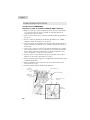
GROUNDING INSTRUCTIONS
This appliance must be grounded. In the event of malfunction or breakdown,
grounding will reduce th risk of electric shock by providing a path of least
resistance for electric current. This appliance is equipped with a cord having an
equipment-grounding conductor and a grounding plug. The plug must be plugged
into an appropriate outlet that is properly installed and grounded in accordance
with all local codes and ordinances. This appliance must be connected to a
grounded metal, permanent wiring system,or an equipment-groundingconductor
must be run with the circuit conductors and connected to the equipment-grounding
terminal or lead on the appliance.

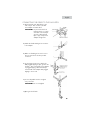
Brass Terminal
Nut
Tighten Nut to
These Threads
Power Cord
Strain Relief
Mounting Bracket
Green Ground
Screw
Neutral
Ground Wire
English
13
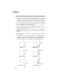
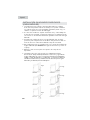
3-Wire Cord Connection (US models only)
1. Remove the screws securing the terminal block access cover and the strain
relief mounting bracket located on the back of the dryer’s upper corner.
2.
Install a U.L. approved strain relief into the power cord entry hole of the
mounting bracket. Finger tighten the nut only at this time.
3. Thread a U.L. Approved 30 Amp. Power cord, NEMA 10-30 Type SRDT,
through the strain relief.
4. Attach the power cord neutral (center wire) conductor to the brass colored
center terminal on the terminal block. Tighten the screw securely.
5. Attach the remaining two power cord outer conductors to the outer brass
colored terminals on the terminal block. Tighten both screws securely.
Warning: Do not make a sharp bend or crimp wiring/conductor at
connections.
6. Reattach the strain relief mounting bracket to the back of the dryer with two
screws. Tighten screws securely.
7. Tighten the screws securing the cord restraint firmly against the power cord.
8. Tighten the strain relief nut securely so that the strain relief does not turn.
9. Reinstall the terminal block cover.
ELECTRICAL CONNECTIONS
ELECTRIC Dryer (RDE350AW)
Terminal Block

English
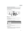
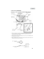
4-Wire Cord Connections (US Models Only)
1. Remove the screws securing the terminal block access cover and the strain
relief mounting bracket located on the back of the dryer upper corner.
2. Install a UL approved strain relief into the power cord entry hole of the
mounting bracket . Finger tighten the nut only at this time.
3. Remove the green neutral ground wire from the green ground screw located
above the terminal block.
Brass Terminal
Red
Tighten Nut to
These Threads
Power Cord
Strain Relief
Mounting Bracket
Green Ground
Screw
Neutral
Ground Wire
Terminal
Block
Black
Nut
Green Power Cord
Ground Wire
Black 240V
White Neutral
Red 240V
Green Ground
Typical Conductor
Receptacle
Typical 4
Conductor Cord
ELECTRIC Dryer (RDE350AW)
14
White

English
15
4. Thread a U.L. approved 30 Amp power cord. NEMA 14-30 type ST or SRDT
through the strain relief.
5. Attach the green power cord ground wire to the cabinet with green ground
screw.
6.
7. Attach the red and black power cord conductors to the outer brass-colored
terminals on the terminal block.
Warning: Do not make a sharp bend or crimp the wiring /conductor at
connections.
8. Tighten the screws securing the cord restraint firmly against the power cord.
9. Tighten the strain relief nut securely so that the strain relief does not turn.
10. Reinstall the terminal block cover.
NOTE: DO NOT connect the dryer to L.P. gas service without
converting the gas valve. An L.P. Conversion Kit must be
installed by a qualified gas technician.
1. Remove the shipping cap from gas pipe at the rear of the dryer.
2. Connect a 1/2 inch (1.27cm) I.D. semi-rigid or approved pipe from gas supply line to
the 3/8 inch (0.96cm) pipe located on the back of the dryer. Use a 1/2 inch to 3/8
inch (1.27cm to 0.96cm) reducer for a connection. Apply an approved thread sealer
that is resistant to the corrosive action of liquified gases on all pipe connections.
3. Open the shutoff valve in the gas supply line.
4. Test all connections by brushing on a soapy water solution. NEVER TEST FOR GAS
LEAKS WITH AN OPEN FLAME.
5. Connect the exhaust duct to the outside exhaust system. Use duct tape to seal all joints.
6. With the dryer in its final position, adjust one or more of the legs until the dryer is resting
solid on all four legs. Place a level on top of the dryer. THE DRYER MUST BE LEVEL
AND RESTING SOLID ON ALL FOUR LEGS.
7. Plug the power cord into a grounded outlet. NOTE: check to ensure power is OFF at
circuit breaker/fuse box before plugging the power cord into the outlet.
8. Turn on the power at the circuit breaker/fuse box.
Before operating the dryer, make sure the dryer area is clean and free
from combustible materials, gasoline, and other flammable vapors. Also
see that nothing (such as boxes, clothing, etc.) obstructs the flow of
combustion and ventilation air through the louvered panel located on the
rear of the dryer.
9. Run the dryer through a cycle check for proper operation.
NOTE: On gas dryers, before the burner will light, it is necessary for the gas line to
be bled of air. If the burner does not light within 45 seconds the first time
the dryer is turned on, the safety switch will shut the burner off. If this
happens, turn the dryer to “OFF” and wait 5 minutes before making
another attempt to light.
NOTE: Follow instructons supplied with kit.
GAS CONNECTIONS
GAS Dryer (RDG350A)
Attach the white (neutral) power cord conductors and the green ground wire
from the dryer harness to the brass-colored center terminal on the terminal
block. Tighten the screw securely.

English
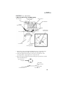
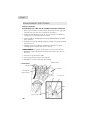
16
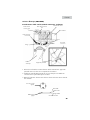
A) Connect female 3/8” NPT elbow to gas
inlet on dryer. Then connect 3/8” flare
union adapter to female elbow.
IMPORTANT: To prevent the inlet from
twisting, please use a pipe
wrench to secure the dryer
gas inlet. Affix Teflon®
tape or pipe compound to
adapter and gas inlet.
B) Attach the flexible metal gas line connector
to the adapter.
C) Make sure flexible gas line seal is secure.
Use two wrenches for the best possible
connection.
D) To check gas inlet pressure, attach 1/8”
NPT plugged tapping to dryer gas line shut-
off valve. Then connect flare union adapter
to plugged tapping. Affix Teflon® tape
to the threads of the adapter and plugged
tapping to ensure seal.
E) Use two adjustable wrenches to tighten
every connection.
IMPORTANT: Do not overtighten!
F) Open gas shut-off valve.
CONNECTING THE DRYER TO THE GAS SUPPLY

English
17
REPLACEMENT PARTS
Replacement parts and accessories for US and Canada can be purchased
through Haier America at 1-800-313-8495
Label all wires prior to disconnection when servicing controls.
Wiring errors can cause improper and dangerous operation. Check
unit for proper operation after servicing.
WARNING
Discard or destroy the carton and plastic bags after the dryer is
unpacked. Children should not be allowed to use them to play with.
Cartons covered in rugs, bedspreads or plastic sheets can become
an airtight chamber and cause suffocation leading to death. Make
all packing materials inaccessible to children.
WARNING
The instructions in this manual and all other literature included with
this dryer can not cover every possible condition and situation that
may occur. Good safe practice and caution must be applied when
installing, operating, and maintaining any appliance. If you are in
doubt after installing, call a certified electrician to install and wire
the dryer.
English

English
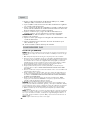
OPERATING INSTRUCTIONS
English
18
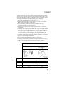
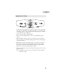
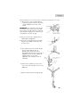
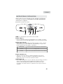
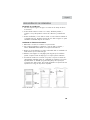
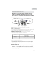
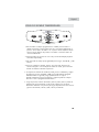
Understanding the Control Panel
Note: Features may vary per model.
Temp Button: (1)
•Used to set drying temperatures. There are four available drying temperatures to
choose from: High, Medium, Low, and Air Fluff.
Cycle Select Dial: (2)
• Select the from 3 Auto-Dry cycles (Heavy Duty, Normal, and Delicates), or
4 Time Dry Cycles (30,60,90 or 120 minutes)
Start/Pause Button (3)
• Push to start after selecting the dry cycle and setting the temperature. Push once
to pause. Push again to start after pushing.
Cycle Progress: (4)
• This indicates the process the cycle is currently in. At the end of the dry cycle
the dryer will automatically go in the wrinkle saves mode. Here the dryer tub
will tumble periodically for 1 hour after the dry cycle is completed. To stop
simply open the door and remove the clothes.
Heavy Duty Heavyweight material such as jeans or bath towels.
Normal Normal drying
Delicate Drying small quantity clothes and delicate fabric.
To reduce the risk of fire, electric shock, or injury to persons,
read all of the IMPORTANT SAFETY INSTRUCTIONS before
using this appliance.
1
Air Fluff
120 min
90 min
60 min
30 min
Timed Dry
Automatic
Super Capacity
2 3 4

English
19
t4PSUDMPUIFTPGUIFTBNFLJOEDPUUPOTZOUIFUJDTXPPMFOUPESZ
t%BSLBOEMJHIUDPMPSFEDMPUIFTTIPVMECFTFQBSBUFMZESJFE'BCSJDTQSPOFUP
losing lint and those prone to adhering lint shall be separately dried. Clothes
prone to falling lint should be turned inside out before putting into the dryer.
t.BLFTVSFCVUUPOTBOEPSOBNFOUTPOUIFDMPUIFTBSFIJHIUFNQFSBUVSF
resistant and won’t damage drum surface. Before loading, the clothes should
have their zippers zipped up, buttons and hooks done up and belts tied so as to
avoid entanglement or other obstacles.
t*GQPTTJCMFUVSOPVUUIFDMPUIFTQPDLFUTGPSVOJGPSNESZJOH
t$IFDLJGDMPUIFTSFNBJOTPJMFE*GTPXBTIUIFNBHBJOPUIFSXJTFTPJMTNBZCF
permanently set.
t4NBMMBSUJDMFTTIPVMECFDPMMFDUFEJOBNFTICBHCFGPSFMPBEJOHBOEESZJOHTP
as to avoid entanglement and ensure easy removal.
t.BLFTVSFUIFQPXFSTPDLFUJTSFMJBCMZHSPVOEFE5IFHSPVOEJOHUFSNJOBMTIPVME
not be connected to gas or tap water pipelines.
t.BLFTVSFFYIBVTUEVDUIBTCFFOQSPQFSMZDPOOFDUFE
t.BLFTVSFMJOUGJMUFSJTDMFBOBOEQSPQFSMZJOTUBMMFE*GMJOUGJMUFSJTOPUJOQMBDF
tumbling items could enter the exhaust system and cause damage to the dryer.
Note: Applies to Auto Dry cycle and Timed Dry cycle.
PREPARATIONS BEFORE DRYING
La page charge ...
La page charge ...
La page charge ...
La page charge ...
La page charge ...
La page charge ...
La page charge ...
La page charge ...
La page charge ...
La page charge ...
La page charge ...
La page charge ...
La page charge ...
La page charge ...
La page charge ...
La page charge ...
La page charge ...
La page charge ...
La page charge ...
La page charge ...
La page charge ...
La page charge ...
La page charge ...
La page charge ...
La page charge ...
La page charge ...
La page charge ...
La page charge ...
La page charge ...
La page charge ...
La page charge ...
La page charge ...
La page charge ...
La page charge ...
La page charge ...
La page charge ...
La page charge ...
La page charge ...
La page charge ...
La page charge ...
La page charge ...
La page charge ...
La page charge ...
La page charge ...
La page charge ...
La page charge ...
La page charge ...
La page charge ...
La page charge ...
La page charge ...
La page charge ...
La page charge ...
La page charge ...
La page charge ...
La page charge ...
La page charge ...
La page charge ...
La page charge ...
La page charge ...
La page charge ...
-
 1
1
-
 2
2
-
 3
3
-
 4
4
-
 5
5
-
 6
6
-
 7
7
-
 8
8
-
 9
9
-
 10
10
-
 11
11
-
 12
12
-
 13
13
-
 14
14
-
 15
15
-
 16
16
-
 17
17
-
 18
18
-
 19
19
-
 20
20
-
 21
21
-
 22
22
-
 23
23
-
 24
24
-
 25
25
-
 26
26
-
 27
27
-
 28
28
-
 29
29
-
 30
30
-
 31
31
-
 32
32
-
 33
33
-
 34
34
-
 35
35
-
 36
36
-
 37
37
-
 38
38
-
 39
39
-
 40
40
-
 41
41
-
 42
42
-
 43
43
-
 44
44
-
 45
45
-
 46
46
-
 47
47
-
 48
48
-
 49
49
-
 50
50
-
 51
51
-
 52
52
-
 53
53
-
 54
54
-
 55
55
-
 56
56
-
 57
57
-
 58
58
-
 59
59
-
 60
60
-
 61
61
-
 62
62
-
 63
63
-
 64
64
-
 65
65
-
 66
66
-
 67
67
-
 68
68
-
 69
69
-
 70
70
-
 71
71
-
 72
72
-
 73
73
-
 74
74
-
 75
75
-
 76
76
-
 77
77
-
 78
78
-
 79
79
-
 80
80


Haier RDE User Manual and Installation Instructions
- Catégorie
- Sèche-linge électriques
- Taper
- User Manual and Installation Instructions
- Ce manuel convient également à
Documents connexes
Autres documents
-
Electrolux EFMG517SIW Mode d'emploi
-
Electrolux EFDE317TIW Le manuel du propriétaire
-
-
-
Bosch HBL8650UC/03 Supplemental
-
Sharp LV-70X500E Le manuel du propriétaire
-
Wolf 820071 Guide d'installation
-
Best MD8TU Guide d'installation
-