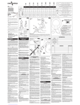
Nomadix AP 6WA Mode d'emploi
- Catégorie
- Points d'accès WLAN
- Taper
- Mode d'emploi

Nomadix AP 6WA Wireless Access Point
Hardware Installation and Reference Guide V1.00

Copyright statement
Nomadix©2021
Nomadix reserves all copyrights of this document. Any reproduction, excerption, backup, modification, transmission,
translation or commercial use of this document or any portion of this document, in any form or by any means, without the
prior written consent of Nomadix is prohibited.
Exemption statement
This document is provided “as is”. The contents of this document are subject to change without any notice. Please obtain
the latest information through the Nomadix website. Nomadix endeavors to ensure content accuracy and will not shoulder
any responsibility for losses and damages caused due to content omissions, inaccuracies or errors.

Preface
Thank you for using our products. This manual will guide you through the installation of the access point.
Scope
It is intended for the users who have some experience in installing and maintaining network hardware. At the same time, it
is assumed that the users are already familiar with the related terms and concepts.
Obtaining Technical Assistance
Nomadix Website: https://nomadix.com
Service Hotline: +1 818-575-2500
Related Documents
Documents Description
Configuration Guide Describes network protocols and related mechanisms that supported by the
product, with configuration examples.
Command Reference Describes the related configuration commands, including command modes,
parameter descriptions, usage guides, and related examples.
Documentation Conventions
The symbols used in this document are described as below:
This symbol brings your attention to some helpful suggestions and references.
This symbol means that you must be extremely careful not to do some things that may damage the device or cause
data loss.

AP 6WA Hardware Installation and Reference Guide Product Overview
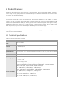
1 Product Overview
Nomadix AP 6WA is designed for indoor scenarios in campuses, hotels, offices and residential buildings. Featuring a
concise design and easy deployment, the AP enables zero disruption to the interior finishes and offers the best solution
for scenarios with delicate interior design.
The dual-radio, dual-band AP supports the latest 802.11ax. And it delivers data rates of up to 574Mbps at 2.4G and
1.2Gbps at 5G with the maximum delivery rate totaling 1.77Gbps. The Wall AP provides four 10/100/1000Base-T LAN
ports and one 10/100/1000Base-T WAN port, delivering optimal wireless network coverage. AP 6WA supports security,
radio frequency (RF) control, mobile access, Quality of Service (QoS) and seamless roaming. Plus, two power supply
modes are provided, so you can choose to power up the AP either by local or PoE power supply.
Teaming up with Nomadix’s Wireless Controller Series, wireless data forwarding, high performance security and access
control can be accomplished with ease.
1.1 Technical Specifications
Table 1-1 Technical Specifications of AP 6WA
Hardware Specifications
Radio 2.4G: 2 x 2MIMO
5G: 2 x 2MIMO
Transmission
Protocol
2.4G : 802.11b/g/n/ac/ax
5G: 802.11a/n/ac/ax
Support concurrent operation of 802.11ax and 802.11a/b/g/n/ac.
Operating Bands
802.11b/g/n/ac/ax: 2.4 GHz to 2.483 GHz
802.11a/n/ac/ax: 5G: 5.150 GHz to 5.350 GHz, 5.47 GHz to 5.725 GHz, 5.725 GHz to 5.85 GHz
(Country-specific)
Antenna Built-in antenna
Spatial Streams 4 streams
Max Throughput 2.4G: up to 574 Mbps
5G: up to 1.2 Gbps
Up to 1.77 Gbps per AP
Modulation DSSS: DBPSK@1Mbps, DQPSK@2Mbps, and [email protected]/11Mbps
OFDM: BPSK@6/9Mbps, QPSK@12/18Mbps, 16-QAM@24Mbps, 64-QAM@48/54Mbps
MIMO-OFDM: QPSK, 16QAM, 64QAM, 256QAM and1024QAM
Receive Sensitivity
11a: -91dBm(1Mbps), -90dBm(5Mbps), -87dBm(11Mbps)
11b/g: -89dBm(6Mbps), -82dBm(24Mbps), -78dBm(36Mbps), -72dBm(54Mbps)
11n: -85dBm@MCS0, -67dBm@MCS7, -67dBm@MCS7
11ac: VHT20: -85dBm(MCS0), -62dBm(MCS8)
11ac: VHT40: -82dBm(MCS0), -57dBm(MCS9)
11ac: VHT80: -79 dBm(MCS0), -53 dBm(MCS9)

AP 6WA Hardware Installation and Reference Guide Product Overview
11ax: HE80: -79 dBm(MCS0), -53 dBm(MCS9),-52 dBm(MCS11)
Max Transmit Power ≤ 100 mw (20 dBm)
(Depending on the country of use, laws and regulations.)
Transmit Power
Adjustment 1 dBm
Dimensions
(W x D x H) 86 mm x 116 mm x 40 mm
Weight ≤ 0.3 kg
Service Ports Four 10/100/1000Base-T LAN ports
One 10/100/1000Base-T WAN port (PoE and PoE+ capable)
Management Ports One Micro USB port for console management
LED Indicators One indicator
Power Supply Local power supply: DC 12 V/1 A
PoE: IEEE 802.3af/802.3at-compliant (compatible).
Power Consumption < 10W
Bluetooth Bluetooth 4.0
iBeacon
Temperature Operating: -10°C to 45°C (14°F to 113°F)
Storage: -40°C to 70°C (-40°F to 158°F)
Humidity Operating: 5% to 95% RH (non-condensing)
Storage: 5% to 95% RH (non-condensing)
Installation Wall mount
IP Rating IP41
Safety Standards GB4943
EN/IEC 60950-1
EMC Standards
GB9254
EN301489
EN50121
EN50155
Radio
China Radio Transmission Equipment Type Approval Certificate
EN300 328
EN301 893
MTBF > 250,000H
FCC Statement
This equipment has been tested and found to comply with the limits for a Class B digital device, pursuant to
part 15 of the FCC Rules. These limits are designed to provide reasonable protection against harmful
interference in a residential installation. This equipment generates, uses and can radiate radio frequency
energy and, if not installed and used in accordance with the instructions, may cause harmful interference to
radio communications. However, there is no guarantee that interference will not occur in a particular
installation. If this equipment does cause harmful interference to radio or television reception, which can be
determined by turning the equipment off and on, the user is encouraged to try to correct the interference by
one or more of the following measures:
—Reorient or relocate the receiving antenna.

AP 6WA Hardware Installation and Reference Guide Product Overview
—Increase the separation between the equipment and receiver.
—Connect the equipment into an outlet on a circuit different from that to which the receiver is connected.
—Consult the dealer or an experienced radio/TV technician for help.
FCC Radiation Exposure Statement
This device complies with FCC radiation exposure limits set forth for an uncontrolled environment and it also
complies with Part 15 of the FCC RF Rules. This equipment must be installed and operated in accordance
with provided instructions and the antenna(s) used for this transmitter must be installed to provide a
separation distance of at least 20 cm from all persons and must not be co-located or operating in conjunction
with any other antenna or transmitter. End-users and installers must be provided with antenna installation
instructions and consider removing the no-collocation statement.
This device complies with Part 15 of the FCC Rules. Operation is subject to the following two conditions:
(1) this device may not cause harmful interference, and
(2) this device must accept any interference received, including interference that may cause undesired
operation.
Caution!
Any changes or modifications not expressly approved by the party responsible for compliance could void the
user's authority to operate the equipment.
Canada Statement
This device contains licence-exempt transmitter(s)/receiver(s) that comply with Innovation, Science and
Economic Development Canada’s licence-exempt RSS(s). Operation is subject to the following two
conditions:
(1) This device may not cause interference.
(2) This device must accept any interference, including interference that may cause undesired operation of
the device.
L’émetteur/récepteur exempt de licence contenu dans le présent appareil est conforme aux CNR d’Innovation,
Sciences et Développement économique Canada applicables aux appareils radio exempts de licence.
L’exploitation est autorisée aux deux conditions suivantes :
1) L’appareil ne doit pas produire de brouillage;
2) L’appareil doit accepter tout brouillage radioélectrique subi, même si le brouillage est susceptible d’en
compromettre le fonctionnement.
The device meets the exemption from the routine evaluation limits in section 2.5 of RSS 102 and compliance
with RSS-102 RF exposure, users can obtain Canadian information on RF exposure and compliance.
Le dispositif rencontre l'exemption des limites courantes d'évaluation dans la section 2.5 de RSS 102 et la
conformité à l'exposition de RSS-102 rf, utilisateurs peut obtenir l'information canadienne sur l'exposition et la
conformité de rf.

AP 6WA Hardware Installation and Reference Guide Product Overview
This transmitter must not be co-located or operating in conjunction with any other antenna or transmitter. This
equipment should be installed and operated with a minimum distance of 20 centimeters between the radiator
and your body.
Cet émetteur ne doit pas être Co-placé ou ne fonctionnant en même temps qu'aucune autre antenne ou
émetteur. Cet équipement devrait être installé et actionné avec une distance minimum de 20 centimètres
entre le radiateur et votre corps.
The device for operation in the band 5150-5250MHz is only for indoor use to reduce the potential for harmful interfe
rence to co-channel mobile satellite systems.
Les dispositifs fonctionnant dans la bande 5150-5250 MHz sont réservés uniquement pour une utilisation
à l’intérieur afin de réduire les risques de brouillage préjudiciable aux systèmes de satellites mobiles
utilisant les mêmes canaux.
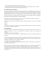
1.2 Product Image
The AP provides two radio ports, one 10/100/1000Base-T Ethernet WAN port, and four 10/100/1000Base-T Ethernet LAN
ports.
Figure 1-1 Image of AP 6WA
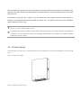
Figure 1-2 Bottom View of AP 6WA

AP 6WA Hardware Installation and Reference Guide Product Overview
Note 1. Four 10/100/1000Base-T LAN ports
Figure 1-3 Side View of AP 6WA
Note
1. Micro USB management port (Console)
2. Reset button
3. Port for local power supply
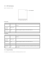
Figure 1-4 Rear View of AP 6WA
Note 1. 10/100/1000Base-T Ethernet WAN port

AP 6WA Hardware Installation and Reference Guide Product Overview
1.3 LED Indicators
Figure 1-5 Indicator on the AP
Fat AP Mode
State Frequency Meaning
Off N/A The AP is powered off. Or the AP is in Silent mode, which can be disabled via
software.
Fast blinking
green before
solid green
2.5 Hz (fast
blinking green)
Initialization is in progress. The AP is operational.
Fast blinking
red
2.5 Hz Firmware upgrade in progress. Do not power off the AP.
Blinking orange 1 Hz AP is operational.
Fit AP Mode
State Frequency Meaning
Off N/A The AP is powered off. Or the AP is in Silent mode, which can be disabled via
software.
Fast blinking
green before
solid green
2.5 Hz (fast
blinking green)
Initialization is in progress. The AP is operational.
Fast blinking
red
2.5 Hz Firmware upgrade in progress. Do not power off the AP.
Blinking orange 1 Hz AP is operational and Ethernet link is down.
Blinking green 1 Hz AP is operational and Ethernet link is up. CAPWAP error.
Slow blinking
green
0.4 Hz AP is operational and CAPWAP connection is established. At least one client is
associated.
1.4 Reset Button
To reset the AP, you need to keep the reset button pressed for 2s or less.

AP 6WA Hardware Installation and Reference Guide Product Overview
To restore default settings, you need to keep the reset button pressed for 3s or more.
1.5 Power Sources
AP 6WA supports two power supply modes: PoE and DC power supply.
PoE power supply:
Input voltage range: 44-57 V
Rated current: 0.3 A
When adopting PoE power supply, make sure the peer end also supports 802.3af/802.3at.
DC power supply:
Input voltage range: 12 V
Rated current: 1 A
1.6 Cooling Solution
The AP adopts fanless design. Keep enough space around the device to guarantee airflow for proper ventilation.

AP 6WA Hardware Installation and Reference Guide Preparing for Installation
2 Preparing for Installation
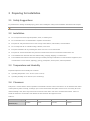
2.1 Safety Suggestions
To prevent device damage and bodily injury, please read carefully the safety recommendations described in this chapter.
The recommendations do not cover all possible hazardous situations.
2.2 Installation
Do not expose the AP to high temperature, dusts, or harmful gases.
Do not install the AP in an inflammable or explosive environment.
Keep the AP away from EMI sources such as large radar stations, radio stations, and substations.
Do not subject the AP to unstable voltage, vibration, and noises.
Keep the installation site dry. Installing the device near sea is not recommended.
Keep the AP at least 500 meters away from the seaside and do not face it toward the wind from the sea.
The installation site should be free from water flooding, seepage, dripping, or condensation.
The installation site shall be selected according to network planning and features of communications equipment, and
considerations such as climate, hydrology, geology, earthquake, electric power, and transportation.
2.3 Temperature and Humidity
Required temperature and humidity are as follows:
Operating temperature: -10°C to 45°C (14°F to 113°F)
Operating humidity: 5% to 95% RH (non-condensing)
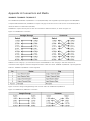
2.4 Cleanness
Dust poses a serious threat to device operation. Dust that falls onto the surface of the device can be absorbed onto metal
contact points by static electricity, resulting in poor contact. Electrostatic absorption of dust occurs more easily when the
relative humidity is low, which may shorten the service life of the device and cause communication failures. Table 2-1
shows the maximum concentration and diameter of dust allowed in the equipment room.
Table 2-1
Maximum diameter (μm) 0.5 1 3 5
Maximum concentration
(Particles/m3) 1.4×10⁷ 7×10⁵ 2.4×10⁵ 1.3×10⁵

AP 6WA Hardware Installation and Reference Guide Preparing for Installation
Besides, the contents of salts, acids and sulfides in the air are also strictly limited for the equipment room. These
substances can accelerate metal corrosion and the aging of some parts. Table 2-2 describes the limit of some hazardous
gases such as SO2, H2S, NO2 and Cl2 in the equipment room.
Table 2-2
Gas Average (mg/m
3
) Maximum (mg/m
3
)
SO2 0.2 1.5
H2S 0.006 0.03
NO2 0.04 0.15
NH3 0.05 0.15
Cl2 0.01 0.3
2.5 Power Supply
PoE injector: IEEE 802.3at/af compliant
DC power adapter:
Input voltage: 12 V
Rated current: 1.0 A
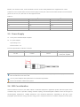
Technical Specifications of the DC Connector
Inner Diameter Outer Diameter Insertion Depth Polarity
2.1 mm 5.5 mm 10 mm Inner pole: positive
Outer pole: negative
The DC input power should be greater than the power actually consumed by the system. The input power for the AP
6WA should not be lower than 10 W.
Use DC power adapters with specifications recommended by Nomadix.
Please use Nomadix certified PoE injectors.
2.6 EMI Consideration
Various interference sources, from either outside or inside the equipment or application system, affect the system in the
conductive ways such as capacitive coupling, inductive coupling, and electromagnetic radiation. There are two types of
electromagnetic interferences: radiated interference and conducted interference, depending on the type of the
propagation path. When the energy, often RF energy, from a component arrives at a sensitive component via the space,

AP 6WA Hardware Installation and Reference Guide Preparing for Installation
the energy is known as radiated interference. The interference source can be both a part of the interfered system and a
completely electrically isolated unit. Conducted interference results from the electromagnetic wire or signal cable
connection between the source and the sensitive component, along the cable the interference conducts from one unit to
another. Conducted interference often affects the power supply of the equipment, but can be controlled by a filter.
Radiated interference may affect any signal path in the equipment, and is difficult to shield.
Effective measures should be taken for the power system to prevent the interference from the electric grid.
The working ground of the routers should be properly separated and kept as far as possible from the grounding
device of the power equipment or the anti-lightning grounding device.
Keep the equipment away from high-power radio transmitter, radar transmitting station, and high-frequency
large-current device.
Measures must be taken to isolate static electricity.
2.7 Installation Tools
Common Tools Phillips (crosshead) screwdriver, copper and fiber cables, bolts, diagonal pliers, cable ties
straight screwdriver (for the removal of the cover)
Special Tools Wire stripper, crimping pliers, RJ-45 crimping pliers, punch down tool, anti-static tools
Meter Multimeter, bit error rate tester (BERT)
The listed tools, apart from bolts, are customer supplied.

AP 6WA Hardware Installation and Reference Guide Installing the Access Point
3 Installing the Access Point
Make sure you have carefully read Chapter 2, and be sure that the requirements set forth in Chapter 2 have been
met.
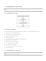
3.1 Installation Flowchart
3.2 Before You Begin
To ensure normal operation and a prolonged useful life of the equipment, observe the following safety precautions:
Install the device in a well-ventilated location.
Do not subject the device to high temperatures.
Keep away from high voltage cables.
Install the device indoors.
Do not expose the device in a thunderstorm or strong electric field.
Keep the device clean and dust-free.
Disconnect the device before cleaning it.
Do not wipe the device with a damp cloth.
Do not wash the device with liquid.
Do not open the enclosure when the AP is working.
Fasten the device tightly.
3.3 Installing the Access Point
Disconnect the device before installing or moving it.
Make sure that the screws are of fine quality.

AP 6WA Hardware Installation and Reference Guide Installing the Access Point
Be sure that the equipment is installed in a place where it is easy to be observed.
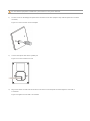
1) Loosen screws on the 86-type faceplate that is mounted on the wall. (Skip this step if the faceplate has not been
mounted.)
Figure 3-1 Loosen Screws on the Faceplate
2) Connect the uplink cable to the UpLNK port.
Figure 3-2 Connect Cables to Ports
3) Align screw holes on both sides of the device over those on the faceplate. And then tighten screws with a
screwdriver.
Figure 3-3 Tighten Screws with a Screwdriver

AP 6WA Hardware Installation and Reference Guide Installing the Access Point
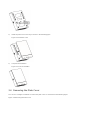
4) Install the plate cover in the way as shown in the following figure.
Figure 3-4 Install the Cover
5) Compete the installation.
Figure 3-5 Cover for AP 6WA
3.4 Removing the Plate Cover
You can use a straight screwdriver to remove the plate cover as constructed in the following figure.
Figure 3-6 Removing the Plate Cover

AP 6WA Hardware Installation and Reference Guide Installing the Access Point

AP 6WA Hardware Installation and Reference Guide System Debugging
4 System Debugging
4.1 Setting up a Debugging Environment
Use a power adapter or PoE to power the AP.
Setting up the Environment
Verify that the AP is properly connected to the power source.
Connect the AP to a wireless controller through a twisted pair cable.
When the AP is connected to a PC for debugging, verify that the PC and PoE switch are properly grounded.
4.2 Powering Up the AP
4.2.1 Checking before power-up
Verify that the power supply is properly connected.
Verify that the input voltage matches the specification of the AP.
4.2.2 Checking after power-up (recommended)
After powering up, it is recommended that you check the following to ensure normal operation of the AP.
Check if any message is displayed on the Web-based configuration interface for the wireless controller.
Check if the LED works normally.
4.3 Reset/Restore Default Settings
The reset button is hidden in a hole and used by technical support personnel. To avoid abnormal operation, do not use
this button without consultation with technical support personnel.
4.3.1 System Reset
Remove the cover. Insert an iron stick, 1mm or less in diameter, into the hole, and slightly press it. After hearing a click,
keep the stick in the same position for 2s. The system reset is complete.
4.3.2 Restore Default Settings
Remove the cover. Insert an iron stick, 1mm or less in diameter, into the hole, and slightly press it. After hearing a click,
keep the stick in the same position for 3s. Default settings are restored.

AP 6WA Hardware Installation and Reference Guide Monitoring and Maintenance
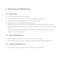
5 Monitoring and Maintenance
5.1 Monitoring
You can observe the LED to monitor the AP in operation.
Fast blinking green followed by solid green: The AP is being initialized and is operational.
Blinking red: The AP is upgrading programs firmware. Do not power off the AP.
Blinking orange: The AP is operational. The Ethernet link is down.
Blinking green (1Hz): The AP is operational, and the Ethernet link is up. But the CAPWAP connection is faulty.
Blinking green (0.4Hz): The AP is operational. The CAPWAP connection is OK. At least one client is associated with
the AP.
Blinking green (one flash every 4 seconds): The AP is operational. No clients are associated with the AP. The
system is in the low consumption mode.
5.2 Remote Maintenance
If the AP operates as a Fat AP, you can login in to the AP remotely for maintenance.
If the AP operates as a Fit AP, you can use the wireless controller to centrally manage and maintain the AP.
5.3 Hardware Maintenance
If the hardware is faulty, please contact our Technical Assistance Center (TAC) for help.

AP 6WA Hardware Installation and Reference Guide Troubleshooting
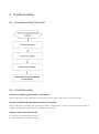
6 Troubleshooting
6.1 Troubleshooting Flowchart
6.2 Troubleshooting
LED does not light up after the AP is powered on
Verify that the power source is IEEE 802.11af compliant. And then verify that the cable is connected properly.
Orange LED blinks after the Ethernet cable is connected
Verify that the device at the other end of the Ethernet cable is working properly. And then verify that the Ethernet cable is
capable of providing the required data rate and is properly connected.
Wireless client cannot find the AP
1) Follow the above-mentioned two steps.
2) Verify that the AP is configured correctly.
La page charge ...
La page charge ...
-
 1
1
-
 2
2
-
 3
3
-
 4
4
-
 5
5
-
 6
6
-
 7
7
-
 8
8
-
 9
9
-
 10
10
-
 11
11
-
 12
12
-
 13
13
-
 14
14
-
 15
15
-
 16
16
-
 17
17
-
 18
18
-
 19
19
-
 20
20
-
 21
21
-
 22
22


Nomadix AP 6WA Mode d'emploi
- Catégorie
- Points d'accès WLAN
- Taper
- Mode d'emploi
dans d''autres langues
- English: Nomadix AP 6WA User guide
Autres documents
-
RP LIGHTING FANS 18042 Mode d'emploi
-
ISC HBxxx Manuel utilisateur
-
 ROCK EXOTICA P55 Mode d'emploi
-
ActionTec API7220 Manuel utilisateur
-
Motorola EX-3524 Guide d'installation
-
-
Dell W-AP124/125 Mode d'emploi
-
Aruba AP-303H Guide d'installation
-
Juniper SRX-MP-WLAN-US How To Install
-
Aruba 630 series Guide d'installation
