Klein Tools VDV500-920 Manuel utilisateur
- Catégorie
- Testeurs de réseau câblé
- Taper
- Manuel utilisateur

INSTRUCTION MANUAL
ENGLISH
VDV500-920
Digital Toner-Pro and
Digital Probe-Pro Kit
Digital Toner-Pro and
Digital Probe-Pro Kit
Digital Toner-Pro and
FRANÇAIS
p. 21
ESPAÑOL
pág. 11
Digital Toner-Pro and
Digital Probe-Pro Kit
Digital Toner-Pro and
Digital Probe-Pro Kit
Digital Toner-Pro and
•
TRACE INDIVIDUAL
OR PAIRED WIRES
•
TRACE SHORTED
OR CONNECTED WIRES
VIA DIGITAL TONING
•
TEST RJ11, RJ12, AND RJ45 JACKS
TEST RJ11, RJ12, AND RJ45 JACKS
•
DETECTS CONTINUITY AND POLARITY
DETECTS CONTINUITY AND POLARITY
•
3 DISTINCT TONES
(2 CONSTANT, 1 ALTERNATING)
(2 CONSTANT, 1 ALTERNATING)
•
EASY-TO-UNDERSTAND
STATUS LED
s
•
SEND TONES ON
SHORTED OR
CONNECTED WIRES
CONNECTED WIRES
VIA DIGITAL TONING
VIA DIGITAL TONING
•
PERFORM
PIN-TO-PIN
MAPPING
•
REPLACEABLE
PROBE TIP
VDV500-223
VDV500-163

2
ENGLISH
GENERAL SPECIFICATIONS - VDV500-163 DIGITAL TONER-PRO
The Klein Tools VDV500-163 Digital Toner-Pro is a professional-series
analog and digital tone generator for wire identification, wire tracing and
wire pair identification. It features several tone frequencies and strong
power output for tracing wires.
•
Operating Altitude:
6562 ft. (2000 m) maximum
•
Relative Humidity:
10% – 90% non-condensing
•
Operating Temp:
32° to 122° F (0° to 50°C)
•
Storage Temp:
-4° to 140°F (-20° to 60°C)
•
Dimensions:
4.65" × 2.52" × 1.10" (118 × 64 × 28 mm)
•
Weight:
5.29 oz. (150 g) including batteries
•
Battery Type:
4 × 1.5V AAA Alkaline
•
Battery Life: Active:
20 hours
Standby/Storage:
3 years
•
Auto-Power Off:
After 60 minutes of inactivity
•
Analog Tones:
Constant:
1000Hz, 1500Hz
Alternating:
1000Hz/1500Hz
•
Tone Power:
8dBm
•
Continuity Indication:
Less than 10kΩ
•
Voltage Protection: Test Mode:
60V
Tone Mode:
20V through external 600Ω
Specifications subject to change.
T17T17
T12T12
T16T16
FEATURE DETAILS - VDV500-163 DIGITAL TONER-PRO
SYMBOLS - VDV500-163 DIGITAL TONER-PRO
Warning or Caution
Conformité Européenne:
Conforms with European
Economic Area directives
Always wear approved
eye protection
UKCA:
UK Conformity Assessment
Do NOT use on
energized circuits
WEEE:
Electronics disposal
Read instructions

3
T1
T1
TEST MODE Indicator
T2
T2
"NRM" (Normal)
Polarity Indicator
T3
T3
"REV" (Reverse)
Polarity Indicator
T4
T4
"CONT" (Continuity)
Indicator
T5
T5
TONE MODE
Indicator
T6
T6
Analog Tone
Frequency Indicators
T7
T7
Digital/Analog Tone
Button
T8
T8
Mode button
T9
T9
Power On/Off Button
T10
T10
Pin/Pair Selection
Button
T11
T11
Battery Status
Indicator
T12
T12
Lanyard Slot
T13
T13
Digital Tone Indicator
T14
T14
Red ABN (Angled
Bed-of-Nails) Test Clip
T15
T15
Black ABN (Angled
Bed-of-Nails) Test Clip
T16
T16
Battery Cover
T17
T17
Battery Cover Screw
T18
T18
Wire Map Indicator
T19
T19
Shield Indicator
T20
Test Lead Inputs
T21
RJ45 Port
T1
T1
T10
T10
T10
T11
T11
T11
T19
T19
T19
T8
T8
T2
T2
T3
T3
T5
T5
T7
T7
T13
T13
T13
T9
T9
T4
T4
FEATURE DETAILS - VDV500-163 DIGITAL TONER-PRO
T15T15
T14T14
T6
T6
T18
T18
T18
WARNINGS
To ensure safe operations and service of the instruments, follow these instructions.
Failure to observe these warnings can result in re, electric shock, severe injury or death.
To ensure safe operations and service of the instruments, follow these instructions.
Failure to observe these warnings can result in re, electric shock, severe injury or death.
To ensure safe operations and service of the instruments, follow these instructions.
•
The Digital Toner-Pro, test leads, and Digital Probe-Pro, are designed for use on extra-low
voltage cabling systems (less than 60V) for testing when
The Digital Toner-Pro, test leads, and Digital Probe-Pro, are designed for use on extra-low
voltage cabling systems (less than 60V) for testing when
The Digital Toner-Pro, test leads, and Digital Probe-Pro, are designed for use on extra-low
NOT
The Digital Toner-Pro, test leads, and Digital Probe-Pro, are designed for use on extra-low
NOT
The Digital Toner-Pro, test leads, and Digital Probe-Pro, are designed for use on extra-low
energized.
The Digital Toner-Pro, test leads, and Digital Probe-Pro, are designed for use on extra-low
energized.
The Digital Toner-Pro, test leads, and Digital Probe-Pro, are designed for use on extra-low
NOT energized.NOT
The Digital Toner-Pro, test leads, and Digital Probe-Pro, are designed for use on extra-low
NOT
The Digital Toner-Pro, test leads, and Digital Probe-Pro, are designed for use on extra-low
energized.
The Digital Toner-Pro, test leads, and Digital Probe-Pro, are designed for use on extra-low
NOT
The Digital Toner-Pro, test leads, and Digital Probe-Pro, are designed for use on extra-low
•
The maximum voltage across ABN Test Clips of the Digital Toner-Pro is 60V in Test
mode, and 20V in Continuity mode. Connecting the Digital Probe-Pro to live mains AC
The maximum voltage across ABN Test Clips of the Digital Toner-Pro is 60V in Test
mode, and 20V in Continuity mode. Connecting the Digital Probe-Pro to live mains AC
The maximum voltage across ABN Test Clips of the Digital Toner-Pro is 60V in Test
power may damage it and pose a safety hazard for the user.
mode, and 20V in Continuity mode. Connecting the Digital Probe-Pro to live mains AC
power may damage it and pose a safety hazard for the user.
mode, and 20V in Continuity mode. Connecting the Digital Probe-Pro to live mains AC
•
DO NOT
use instruments if they are wet, as it could pose a shock hazard.
DO NOT use instruments if they are wet, as it could pose a shock hazard.DO NOT
•
DO NOT
use instruments if they are damaged in any way.
DO NOT use instruments if they are damaged in any way.DO NOT
•
Turn off instruments and disconnect all ABN Test Clips before attempting to replace batteries.
•
The battery door must be in place and secure before you operate the instrument.
•
DO NOT
open the case, other than the battery compartment.
DO NOT open the case, other than the battery compartment.DO NOT
T21
T21
T21
T20
T20
T20

4
ENGLISH
GENERAL SPECIFICATIONS - VDV500-223 DIGITAL PROBE-PRO
The Klein Tools VDV500-223 Digital Probe-Pro is a professional-series
digital and analog tone tracer, featuring an inductive probe with speaker
for amplification, and LED light for use in dark spaces. It also features a
headphone jack for use in extreme noise environments.
•
Operating Altitude:
6562 ft. (2000 m) maximum
•
Relative Humidity:
10% – 90% non-condensing
•
Operating Temp:
14° to 122°F (-10° to 50°C)
•
Storage Temp:
-4° to 140°F (-20° to 60°C)
•
Dimensions:
1.92" × 9.96" × 1.32" (49 × 253 × 34 mm)
•
Weight:
6.88 oz. (195 g) including batteries
•
Battery Type:
4 × 1.5V AAA Alkaline
•
Battery Life: Active:
20 hours
Standby/Storage:
3 years
•
Auto-Power Off:
After 15 minutes of inactivity
Specifications subject to change.
*
CAUTION:
Excessive volume can cause permanent hearing damage.
Use as low a volume as possible.
FEATURE DETAILS - VDV500-223 DIGITAL PROBE-PRO
P1
Replaceable Inductive Polymer Tip (VDV999-070)
P2
Worklight
P3
Power/Worklight On/Off Button
P4
Wire Map Indicators*
P5
Shield Indicator*
*P4 + P5 together constitute Signal Strength Indicator Bars
P6
Volume Increase Button
P7
Volume Decrease Button
P8
Battery Status Indicator
P9
Speaker
P10
Lanyard Slot
P11
Digital Toning Mode Button
P12
Analog Toning Mode / 60Hz Filter On/Off Button
P13
Filter Indicator
P14
RJ45 Port
P15
Battery Cover
P16
Battery Cover Screw (#2 Phillips)
P17
3.5mm Headphone Jack*
SYMBOLS - VDV500-223 DIGITAL PROBE-PRO
Warning or Caution
Conformité Européenne:
Conforms with European
Economic Area directives
Always wear approved
eye protection
UKCA:
UK Conformity Assessment
Do NOT use on
energized circuits
WEEE:
Electronics disposal
Read instructions

5
FEATURE DETAILS - VDV500-223 DIGITAL PROBE-PRO
P2
P2
P17P17
P3
P3
P9
P9
P6
P6
P7
P7
P11
P11
P14
P14
P14
P12P12
P13P13
P8
P8
P5
P5
P10P10
P15P15
P16
P16
P16
P1
P1
P4
P4
WARNINGS
To ensure safe operations and service of the instrument, follow these
instructions. Failure to observe these warnings can result in re,
electric shock, severe injury or death.
•
The Digital Probe-Pro is designed for use on extra-low voltage cabling
systems (less than 60V) for testing when
NOT
energized.
•
DO NOT
use instrument if wet, as it could pose a shock hazard.
•
DO NOT
use instrument if damaged in any way.
•
Turn off instrument before attempting to replace batteries.
•
The battery door must be in place and secure before you operate the
instrument.
•
DO NOT
open the case, other than the battery compartment.

6
ENGLISH
OPERATING INSTRUCTIONS
READ ALL INSTRUCTIONS BEFORE OPERATING AND RETAIN
INSTRUCTIONS FOR FUTURE REFERENCE
TURNING DIGITAL PROBE-PRO AND WORKLIGHT ON/OFF
1.
Turn the probe on by pressing the Power On/Off Button
P3
once.
once.
2.
When the probe is on, press the Power On/Off Button
Turn the probe on by pressing the Power On/Off Button
P3
to turn the worklight on/off.
to turn the worklight on/off.
3.
To turn off the probe, press and hold the Power On/Off Button
to turn the worklight on/off.
P3
for more
for more
than 2 seconds.
TONE MODE
4.
Turn Digital Toner-Pro on by pressing the Power On/Off button
T9
.
5.
The Toner defaults to Digital Tone Mode, with the Digital Tone Indicator
T13
T13
T13
,
and Wire Map Indicator
The Toner defaults to Digital Tone Mode, with the Digital Tone Indicator
T18
T18
T18
LEDs 3 and 6 illuminated. The LEDs may be
LEDs 3 and 6 illuminated. The LEDs may be
blinking, depending on whether the Toner is connected to a network port.
6.
Set the tone mode to either digital toning or analog toning by pressing
the Digital/Analog Tone Button
Set the tone mode to either digital toning or analog toning by pressing
T7
T7
to cycle thru the different options. The
Digital Tone Indicator
the Digital/Analog Tone Button
T13T13
, will illuminate when in digital toning mode.
One or both Analog Tone Frequency Indicators
, will illuminate when in digital toning mode.
T6
T6
will illuminate when in
will illuminate when in
analog toning mode. There are three frequencies available to choose from
when in analog mode: 1000Hz, 1500Hz, and 1000/1500Hz warble.
NOTE:
When performing analog toning via the RJ45 port, the tone can be sent
down an individual pin, a pin pair, or to all eight pins simultaneously. To cycle
thru the analog tone options, repeatedly press the Pin/Pair Selector Button
down an individual pin, a pin pair, or to all eight pins simultaneously. To cycle
T10
T10
T10
to select the desired mode. The Wire Map Indicator
thru the analog tone options, repeatedly press the Pin/Pair Selector Button
T18T18
will illuminate which pin
or pin pairs will be toned. When performing digital toning via the RJ45 port, the
signal is only sent to pin pair 3-6. Wire Map Indicator LEDs 3 and 6 will blink if
toner is connected to an active network port, otherwise LEDs 3 and 6 will remain
constantly illuminated.
TRACING PAIRED WIRES (FIG. 1)
1.
Co
nnect the Digital Toner-Pro’s red
T14
T14
and black
T15T15
ABN Test Clip leads to their
ABN Test Clip leads to their
respective Test Lead Inputs
nnect the Digital Toner-Pro’s red
T20
T20
T20
T20
2.
Connect the red ABN Test Clip
T14
T14
to one of the wires of the pair to be traced.
Connect the black ABN Test Clip
Connect the red ABN Test Clip
Connect the black ABN Test Clip
Connect the red ABN Test Clip
Connect the black ABN Test Clip
to one of the wires of the pair to be traced.
T15T15
to the other wire to be traced.
to the other wire to be traced.
3.
Turn Digital Toner-Pro on by pressing the Power On/Off button
T9
.
4.
The Toner defaults to Digital Tone Mode, with the Digital Tone Indicator
The Toner defaults to Digital Tone Mode, with the Digital Tone Indicator
T13
T13
T13
,
and Wire Map Indicator
The Toner defaults to Digital Tone Mode, with the Digital Tone Indicator
T18
T18
T18
T18
T18
LEDs 3 and 6 illuminated. The LEDs
LEDs 3 and 6 illuminated. The LEDs
may be blinking, depending on whether the Toner is connected to
a network port.
When performing analog toning, check the "CONT"
Indicator
a network port.
T4
. If illuminated green, you may proceed.
NOTE:
When performing Digital Toning, the "CONT" Indicator
T4
will
not illuminate.
5.
Select the preferred tone setting using the Digital/Analog Tone Button
T7
T7
6.
Turn the Digital Probe-Pro on by pressing the Power On/Off button
P3
.
7.
At the far end of the cable, spread the wires apart at least 2" (51 mm), if possible.
8.
If performing analog toning, first ensure the Digital Toner-Pro is set to analog
toning mode. Then ensure the Digital Probe-Pro is set to analog mode by
pressing the Analog Mode button
toning mode. Then ensure the Digital Probe-Pro is set to analog mode by
P12
P12
P12
. The Analog Mode Button will illuminate
green when in analog mode. If performing digital toning, first ensure the
Digital Toner-Pro is set to digital toning mode. Then ensure the Digital Probe-
Pro is set to digital mode by pressing the Digital Mode Button
Digital Toner-Pro is set to digital toning mode. Then ensure the Digital Probe-
P11
P11
. The Digital
Mode Button will illuminate blue when in digital mode.
9.
Use the Digital Probe-Pro to scan the cable’s wire pairs. Move the Digital Probe-
Pro's tip
Use the Digital Probe-Pro to scan the cable’s wire pairs. Move the Digital Probe-
P1
slowly across the wires (FIG. 1). The Digital Probe-Pro’s volume and
slowly across the wires (FIG. 1). The Digital Probe-Pro’s volume and
Signal Strength Indicator bars
slowly across the wires (FIG. 1). The Digital Probe-Pro’s volume and
P4
+
+
slowly across the wires (FIG. 1). The Digital Probe-Pro’s volume and
P5
will increase as it approaches the toned
will increase as it approaches the toned
pair. When the Digital Probe-Pro’s volume and Signal Strength Indicator bars
are high over the first wire, low in the middle (between) the two wires, and high
over the second wire, you have located the pair of wires you are tracing. Use the
Volume Increase
over the second wire, you have located the pair of wires you are tracing. Use the
P6
and
and
Volume Decrease
over the second wire, you have located the pair of wires you are tracing. Use the
P7
buttons to adjust the volume.
buttons to adjust the volume.

7
OPERATING INSTRUCTIONS
TRACING NON-PAIRED WIRES (FIG. 2)
1.
Connect the Digital Toner-Pro’s red
T14
T14
and black
T15T15
ABN Test Clip leads to their
ABN Test Clip leads to their
respective Test Lead Inputs
Connect the Digital Toner-Pro’s red
T20
T20
T20
2.
Connect the Digital Toner-Pro’s red ABN Test Clip
T14
T14
to the wire to be traced.
to the wire to be traced.
3.
Connect the black ABN Test Clip
T15T15
to another wire in the cable, but preferably
to another wire in the cable, but preferably
not in the same pair (connect to ground, if available). When tracing a shielded
not in the same pair (connect to ground, if available). When tracing a shielded
not in the same pair (connect to ground, if available). When tracing a shielded
cable, connect the red ABN Test Clip to the outer shield, and the black ABN
not in the same pair (connect to ground, if available). When tracing a shielded
cable, connect the red ABN Test Clip to the outer shield, and the black ABN
not in the same pair (connect to ground, if available). When tracing a shielded
Test Clip to the center conductor or ground.
cable, connect the red ABN Test Clip to the outer shield, and the black ABN
Test Clip to the center conductor or ground.
cable, connect the red ABN Test Clip to the outer shield, and the black ABN
4.
Turn Digital Toner-Pro on by pressing the Power On/Off button
T9
.
5.
The Toner defaults to Digital Tone Mode, with the Digital Tone Indicator
The Toner defaults to Digital Tone Mode, with the Digital Tone Indicator
T13
T13
T13
,
and Wire Map Indicator
The Toner defaults to Digital Tone Mode, with the Digital Tone Indicator
T18
T18
T18
T18
T18
LEDs 3 and 6 illuminated. The LEDs
LEDs 3 and 6 illuminated. The LEDs
may be blinking, depending on whether the Toner is connected to a
network port.
The "CONT" Indicator
may be blinking, depending on whether the Toner is connected to a
T4
illuminates green or red only when
illuminates green or red only when
in analog mode.
When performing analog toning, check the "CONT"
When performing analog toning, check the "CONT"
When performing analog toning, check the "CONT"
illuminates green or red only when
When performing analog toning, check the "CONT"
illuminates green or red only when
Indicator
in analog mode.
T4
. If illuminated green, you may proceed.
NOTE:
When performing Digital Toning, the "CONT" Indicator
T4
will
not illuminate.
6.
Turn the Digital Probe-Pro on by pressing the Power On/Off button
P3
.
7.
Select the preferred tone setting using the Digital/Analog Tone Button
T7
T7
.
8.
At the far end of the cable, spread the wires at least 2" (51 mm) apart, if possible.
9.
If performing analog toning, first ensure the Digital Toner-Pro is set to analog
toning mode. Then ensure the Digital Probe-Pro is set to analog mode by
pressing the Analog Mode button
toning mode. Then ensure the Digital Probe-Pro is set to analog mode by
P12
P12
P12
. The Analog Mode Button will illuminate
green when in analog mode. If performing digital toning, first ensure the
Digital Toner-Pro is set to digital toning mode. Then ensure the Digital Probe-
Pro is set to digital mode by pressing the Digital Mode Button
Digital Toner-Pro is set to digital toning mode. Then ensure the Digital Probe-
P11
P11
. The Digital
Mode Button will illuminate blue when in digital mode.
10.
Use the Digital Probe-Pro to scan the cable’s wire pairs. Move the Digital Probe-
Pro's tip
Use the Digital Probe-Pro to scan the cable’s wire pairs. Move the Digital Probe-
P1
slowly across the wires (FIG. 2). The Digital Probe-Pro’s volume
slowly across the wires (FIG. 2). The Digital Probe-Pro’s volume
and Signal Strength Indicator bars
slowly across the wires (FIG. 2). The Digital Probe-Pro’s volume
P4
+
+
slowly across the wires (FIG. 2). The Digital Probe-Pro’s volume
P5
will increase as it approaches the
will increase as it approaches the
toned pair. When the Digital Probe-Pro’s volume and Signal Strength Indicator
bars are high over the first wire, low in the middle (between) the two wires, and
high over the second wire, you have located the pair of wires you are tracing. Use
the
Volume Increase
high over the second wire, you have located the pair of wires you are tracing. Use
P6
and
and
Volume Decrease
high over the second wire, you have located the pair of wires you are tracing. Use
P7
buttons to adjust the volume.
buttons to adjust the volume.
FIG. 1
2"
(51 mm)

8
ENGLISH
OPERATING INSTRUCTIONS
RJ11 / RJ12 / RJ45 TESTING
The Digital Toner-Pro has an
RJ45 Test Port
T21
T21
T21
that can be used in place of
that can be used in place of
the ABN clips to transmit the tone. The RJ45 plug works with RJ11, RJ12,
or RJ45 jacks. The
red
the ABN clips to transmit the tone. The RJ45 plug works with RJ11, RJ12,
T14
T14
and black
the ABN clips to transmit the tone. The RJ45 plug works with RJ11, RJ12,
T15T15
ABN Test Clip leads
ABN Test Clip leads
are replaced by
the two center conductors of the inserted plug, i.e. pins 2 and 3 for RJ11,
pins 3 and 4 for RJ12, and pins 4 and 5 for RJ45.
Use the Digital Probe-Pro to locate the toned wires at the far end of the cable,
as described in the
TRACING PAIRED WIRES
section.
CONTINUITY TEST (ANALOG TONING ONLY)
The Digital Toner-Pro transmits frequencies on non-energized wires only. When
the Digital Toner-Pro is turned on, a continuity test will be performed to determine
if the 2 wires to be traced are in close proximity to each other, without a conductive
path between them. The "CONT" Indicator
if the 2 wires to be traced are in close proximity to each other, without a conductive
T4
T4
wIll illuminate green to indicate
wIll illuminate green to indicate
pass. Attach the red and black ABN Test Clips
wIll illuminate green to indicate
T14
T14
T14
T14
T14
,
wIll illuminate green to indicate
T15T15
to the wires to be tested.
to the wires to be tested.
If the resistance of the circuit is less than 10kΩ, the "CONT" Indicator
T4
T4
will
will
illuminate red, indicating a short, and no toning can occur. If the "CONT" Indicator
is illuminated green, a tone can be generated and testing can proceed.
FIG. 2
2"
(51 mm)
POLARITY AND VOLTAGE PRESENCE TESTING
The Digital Toner-Pro may be used to test the polarity and type of voltage
present.
1.
If testing via the RJ45 PORT
T21
T21
T21
, proceed directly to step 2. If testing via the
ABN Test Leads, connect the Digital Toner-Pro’s red
, proceed directly to step 2. If testing via the
T14
T14
and black
, proceed directly to step 2. If testing via the
T15T15
ABN
ABN
Test Clip leads to their respective Test Lead Inputs
ABN Test Leads, connect the Digital Toner-Pro’s red
T20
T20
T20
.
2.
Connect the
ABN Test Clips
, or insert a cable into the RJ45 PORT
T21
T21
T21
.
3.
Turn Digital Toner-Pro on by pressing the Power On/Off button
T9
.
4.
Select Test Mode by pressing the Mode Button
T8
T8
repeatedly
repeatedly
until the
repeatedly
until the
repeatedly
Test Mode Indicator
Select Test Mode by pressing the Mode Button
T1
T1
is illuminated.
is illuminated.
USING THE 60HZ FILTER
The Digital Probe-Pro has a 60Hz filter to help trace cables/wires when toning
near devices running on 60Hz. Press the Analog Toning Mode / 60Hz Filter
The Digital Probe-Pro has a 60Hz filter to help trace cables/wires when toning
near devices running on 60Hz. Press the Analog Toning Mode / 60Hz Filter
The Digital Probe-Pro has a 60Hz filter to help trace cables/wires when toning
On/Off Button
P12
P12
P12
to turn the 60Hz filter on/off. The Filter Indicator
to turn the 60Hz filter on/off. The Filter Indicator
P13P13
will
will
illuminate when the 60Hz filter is on.
illuminate when the 60Hz filter is on.
illuminate when the 60Hz filter is on.
illuminate when the 60Hz filter is on.
NOTE: 60Hz filtering can only be used with analog toning.

9
OPERATING INSTRUCTIONS
5.
Check the “CONT” Indicator
T4
. If illuminated green, testing can proceed.
6.
The
"NRM" (Normal) Polarity Indicator
T2
will illuminate if the red
will illuminate if the red
ABN
Test Clip
"NRM" (Normal) Polarity Indicator
T14
T14
is connected to the POTS (Plain Ol' Telephone Service) in the
is connected to the POTS (Plain Ol' Telephone Service) in the
proper orientation. The
"REV" (Reverse) Polarity Indicator
is connected to the POTS (Plain Ol' Telephone Service) in the
T3
will illuminate
will illuminate
if the wires are reversed.
•
The
"NRM" (Normal) Polarity Indicator
T2
will illuminate
will illuminate
when the black
ABN Test Clip detects higher voltage than the red ABN Test Clip.
•
The
"REV" (Reverse) Polarity Indicator
T3
w
w
ill illuminate
when the red
ABN Test Clip detects higher voltage than the black ABN Test Clip.
•
The
"NRM" (Normal) Polarity Indicator and "REV" (Reverse) Polarity
Indicator will both illuminate when
AC voltage is present.
•
When the
RJ11 Test Plug
is used, the
"NRM" (Normal) Polarity Indicator
will illuminate on
a correctly wired and powered POTS (Plain Ol'
Telephone Service) phone jack.
NOTE
:
The POTS (Plain Ol' Telephone Service) color code convention
(black/positive, red/negative) is the opposite of the multimeter color
code convention (red/positive, black/negative).
RJ45 TERMINATED DATA CABLE WIRE MAP TESTING
1.
Insert one end of the data cable to be tested into the RJ45 port
T21
T21
T21
on the
on the
Digital Toner-Pro.
2.
Insert the opposite end of the cable into the Digital Probe-Pro’s RJ45 Port
P14
P14
P14
.
3.
Enter MAPPING mode by pressing the MODE button
T8
T8
until the Wire Map
until the Wire Map
Indicators
Enter MAPPING mode by pressing the MODE button
T18T18
illuminate and blink. The Digital Probe-Pro will automatically go
illuminate and blink. The Digital Probe-Pro will automatically go
into mapping mode when the toner is set to mapping mode.
4.
A wire pin-to-pin map will be displayed on both the Toner and Probe. The
Toner’s Wire Map Indicators
A wire pin-to-pin map will be displayed on both the Toner and Probe. The
T18T18
will slowly blink in order 1 thru 8, to indicate
will slowly blink in order 1 thru 8, to indicate
which pin on the Toner end of the cable is being mapped. Simultaneously,
the Probe's Wire Map Indicators
which pin on the Toner end of the cable is being mapped. Simultaneously,
P4
P4
will illuminate to indicate which pin on
will illuminate to indicate which pin on
the Probe end of the cable is connected to the actively indicated pinout on the
Toner end; this enables detection of mis-wired cables and cable faults (for
example, if pin 3 on the Toner end of the cable is connected to pin 6 on the
Probe end of the cable, when the Toner's #3 Wire Map Indicator illuminates,
the Probe's #6 Wire Map Indicator will illuminate).
5.
If the cable being mapped is terminated in T568A, T568B, or Straight-
Through wiring, the Probe's Wire Map Indicators will illuminate 1 through 8,
in the order of contact pin termination, in unison with the Toner's Wire Map
Indicators
in the order of contact pin termination, in unison with the Toner's Wire Map
T18T18
. A short circuit between wires is indicated by simultaneously
illuminating all effected wires' LEDs on both the toner and probe during the
detection sequence. For an open circuit, the wire's LEDs on both the toner and
probe will not be illuminated during the detection sequence.
6.
If the cable being tested is shielded, the Shield Indicator on both the Toner
T19T19
and Probe
If the cable being tested is shielded, the Shield Indicator on both the Toner
P5
P5
will illuminate at the end of each sequence.
will illuminate at the end of each sequence.
7.
The test will be repeated until one or both ends of the cable is/are
disconnected, or until the Toner’s mode is cycled out of Mapping mode.
NOTE: The Digital Probe-Pro cannot ID digital/analog tone signals while in
mapping mode.

10
ENGLISH
CUSTOMER SERVICE
KLEIN TOOLS, INC.
450 Bond Street Lincolnshire, IL 60069 1-800-553-4676
www.kleintools.com
CLEANING
Be sure equipment is turned off and wipe with a clean, dry lint-free
cloth.
Do not use abrasive cleaners or solvents.
STORAGE
Remove the batteries when equipment is not in use for a prolonged period
of time. Do not expose to high temperatures or humidity. After a period
of storage in extreme conditions exceeding the limits mentioned in the
GENERAL SPECIFICATIONS
section, allow the equipment to return to
normal operating conditions before using.
FCC & IC COMPLIANCE
See this product’s page at
www.kleintools.com
for FCC compliance
information.
Canada ICES-003 (B) / NMB-003 (B)
WARRANTY
www.kleintools.com/warranty
DISPOSAL / RECYCLE
Do not place equipment and its accessories in the trash. Items must
be properly disposed of in accordance with local regulations. Please
see
www.epa.gov/recycle
for additional information.
MAINTENANCE
– VDV500-163 DIGITAL TONER-PRO
BATTERY REPLACEMENT
When the Low Battery Indicator
T11
T11
blinks, the batteries must be replaced.
1.
Turn off instrument(s) before attempting to replace batteries.
2.
Loosen screw
T17
T17
,
on battery cover
T16T16
.
3.
Remove and properly dispose of four 1.5V AAA batteries.
4.
Install new batteries (note proper polarity).
5.
Replace battery cover and fasten securely with screw.
To avoid risk of electric shock, do not operate while battery door
is removed.
MAINTENANCE
– VDV500-223 DIGITAL PROBE-PRO
BATTERY REPLACEMENT
When the Battery Status Indicator
P8
blinks, the batteries must be replaced.
blinks, the batteries must be replaced.
1.
Turn off instrument(s) before attempting to replace batteries.
2.
Loosen screw
P16P16
on battery cover
on battery cover
P15P15
.
3.
Remove and properly dispose of four 1.5V AAA batteries.
4.
Install new batteries (note proper polarity).
5.
Replace battery cover and fasten securely with screw.
TIP REPLACEMENT (KLEIN CAT. NO. VDV999-070)
The tip
P1
of the Digital Probe-Pro is replaceable if damaged:
of the Digital Probe-Pro is replaceable if damaged:
1.
Turn tip 1/4 turn and pull gently to remove.
2.
Insert new tip with key in proper orientation and push gently.
3.
Rotate 1/4 turn to lock into place.
To avoid risk of electric shock, do not operate while battery door
is removed.

MANUAL DE INSTRUCCIONES
Kit de Digital Toner-Pro
y Digital Probe-Pro
Kit de Digital Toner-Pro
y Digital Probe-Pro
Kit de Digital Toner-Pro
VDV500-920
ESPAÑOL
Kit de Digital Toner-Pro
y Digital Probe-Pro
Kit de Digital Toner-Pro
y Digital Probe-Pro
Kit de Digital Toner-Pro
•
RASTREA ALAMBRES INDIVIDUALES
RASTREA ALAMBRES INDIVIDUALES
Y DEPAR
•
RASTREE LOS CABLES QUE ESTÁN
RASTREE LOS CABLES QUE ESTÁN
EN CORTOCIRCUITO O CONECTADOS
EN CORTOCIRCUITO O CONECTADOS
ATRAVÉS DE LA IDENTIFICACIÓN DE
ATRAVÉS DE LA IDENTIFICACIÓN DE
CABLES DIGITAL
•
PRUEBA CONECTORES RJ11, RJ12 Y RJ45
PRUEBA CONECTORES RJ11, RJ12 Y RJ45
•
DETECTA CONTINUIDAD YPOLARIDAD
DETECTA CONTINUIDAD YPOLARIDAD
•
3TONOS DISTINTOS
(2CONSTANTES, 1ALTERNANTE)
(2CONSTANTES, 1ALTERNANTE)
•
LED DE ESTADO FÁCILES
DE ENTENDER
•
ENVÍE TONOS EN
LOS CABLES QUE
ESTÁN EN
LOS CABLES QUE
ESTÁN EN
LOS CABLES QUE
CORTOCIRCUITO
OCONECTADOS A
TRAVÉS DE LA
IDENTIFICACIÓNDE
CABLES DIGITAL
•
REALICE MAPEO
DE CABLES DE
CLAVIJA ACLAVIJA
•
PUNTA DE
SONDA
REEMPLAZABLE
VDV500-223
VDV500-163

12
ESPECIFICACIONES GENERALES - VDV500-163 DIGITAL TONER-PRO
El Digital Toner-Pro VDV500-163 de Klein Tools es un generador de tono
analógico y digital de serie profesional para identificación de alambres, rastreo
de alambres e identificación de pares de alambres. Ofrece varias frecuencias
de tono y una salida de gran potencia para el rastreo de alambres.
•
Altitud de funcionamiento:
6562' (2000m) como máximo
•
Humedad relativa:
10% a 90%, sin condensación
•
Temperatura de funcionamiento:
32 a 122°F (0 a 50°C)
•
Temperatura de almacenamiento:
-4 a 140°F (-20 a 60°C)
•
Dimensiones:
4,65" × 2,52" × 1,10" (118 × 64 × 28 mm)
•
Peso:
5,29 oz. (150 g) incluidas las baterías
•
Tipo de batería:
4baterías AAA alcalinas de 1,5V
•
Vida útil de la batería: En actividad:
20horas
Modo en espera/Almacenamiento:
3años
•
Función de apagado automático:
después de 60minutos de inactividad
•
Tonos analógicos:
Constante:
1000Hz, 1500Hz
Alternante:
1000Hz/1500Hz
•
Potencia del tono:
8dBm
•
Indicador de continuidad:
Menos de 10kΩ
•
Protección de voltaje: Modo de prueba:
60V
Modo de tono:
20V por medio de 600Ω externos
Especificaciones sujetas a cambios.
T17T17
T12T12
T16T16
DETALLES DE LAS CARACTERÍSTICAS - VDV500-163 DIGITAL TONER-PRO
SÍMBOLOS - VDV500-163 DIGITAL TONER-PRO
Advertencia
oprecaución
Conformité Européenne:
Cumple con las normas del
Espacio Económico Europeo
Siempre debe usar
protección para los
ojos aprobada
UKCA:
Conformidad evaluada por
elReino Unido
NO utilizar en circuitos
energizados
WEEE:
Eliminación de elementos
electrónicos
Lea las instrucciones
ESPAÑOL

13
Indicador “TEST MODE”
(modo de prueba)
Indicador de polaridad
“NRM” (normal)
Indicador de polaridad
“REV” (inversa)
Indicador “CONT”
(continuidad)
Indicador “TONE MODE”
(modo de tono)
T6
Indicadores de
frecuencia de
tonoanalógicos
Botón de tono
digital/analógico
Botón “MODE” (modo)
Botón de encendido
yapagado
Botón de selección
depar/polo
Indicador de estado de
la batería
Ranura para cuerda
Indicador de tono digital
Pinza de prueba con ABN
(bornes de conexión
multicontacto en ángulo)
roja
Pinza de prueba con ABN
(bornes de conexión
multicontacto en ángulo)
negra
Cubierta del
compartimiento
delasbaterías
Tornillo de la cubierta del
compartimiento delas
baterías
T18
Indicador de
mapadecables
T19
Indicador “S”
(conblindaje)
T20
Entradas de cables
deprueba
T21
Puerto RJ45
DETALLES DE LAS CARACTERÍSTICAS - VDV500-163 DIGITAL TONER-PRO
T7
T8
T9
T10
T11
T12
T13
T14
T15
T16
T17
T1
T2
T3
T4
T5
T6
T1
T1
T10
T10
T10
T11
T11
T11
T19
T19
T19
T8
T8
T2
T2
T3
T3
T5
T5
T7
T7
T13
T13
T13
T9
T9
T4
T4
T6
T6
T18
T18
T18
T21
T21
T21
T20
T20
T20
ADVERTENCIAS
Para garantizar el funcionamiento y servicio seguros de los instrumentos, siga
estas instrucciones. El incumplimiento de estas advertencias puede provocar un
Para garantizar el funcionamiento y servicio seguros de los instrumentos, siga
estas instrucciones. El incumplimiento de estas advertencias puede provocar un
Para garantizar el funcionamiento y servicio seguros de los instrumentos, siga
incendio, choque eléctrico, lesiones graves o la muerte.
estas instrucciones. El incumplimiento de estas advertencias puede provocar un
incendio, choque eléctrico, lesiones graves o la muerte.
estas instrucciones. El incumplimiento de estas advertencias puede provocar un
•
El Digital Toner-Pro, los cables de prueba, y el Digital Probe-Pro (se venden por separado),
están diseñados para ser utilizados en sistemas de cableado de voltaje extra bajo (menos de
El Digital Toner-Pro, los cables de prueba, y el Digital Probe-Pro (se venden por separado),
están diseñados para ser utilizados en sistemas de cableado de voltaje extra bajo (menos de
El Digital Toner-Pro, los cables de prueba, y el Digital Probe-Pro (se venden por separado),
60voltios) para pruebas cuando estos sistemas
están diseñados para ser utilizados en sistemas de cableado de voltaje extra bajo (menos de
60voltios) para pruebas cuando estos sistemas
están diseñados para ser utilizados en sistemas de cableado de voltaje extra bajo (menos de
NO
están diseñados para ser utilizados en sistemas de cableado de voltaje extra bajo (menos de
NO
están diseñados para ser utilizados en sistemas de cableado de voltaje extra bajo (menos de
están energizados.
están diseñados para ser utilizados en sistemas de cableado de voltaje extra bajo (menos de
están energizados.
están diseñados para ser utilizados en sistemas de cableado de voltaje extra bajo (menos de
•
La tensión máxima entre las pinzas de prueba con ABN del Digital Toner-Pro es de
60voltios) para pruebas cuando estos sistemas
La tensión máxima entre las pinzas de prueba con ABN del Digital Toner-Pro es de
60voltios) para pruebas cuando estos sistemas
60voltios en el modo de Prueba y de 20voltios en el modo de continuidad. Conectar el
La tensión máxima entre las pinzas de prueba con ABN del Digital Toner-Pro es de
60voltios en el modo de Prueba y de 20voltios en el modo de continuidad. Conectar el
La tensión máxima entre las pinzas de prueba con ABN del Digital Toner-Pro es de
Digital Probe-Pro a una fuente de alimentación de CA activa puede dañarlo e implicar un
60voltios en el modo de Prueba y de 20voltios en el modo de continuidad. Conectar el
Digital Probe-Pro a una fuente de alimentación de CA activa puede dañarlo e implicar un
60voltios en el modo de Prueba y de 20voltios en el modo de continuidad. Conectar el
riesgo de seguridad para el usuario.
Digital Probe-Pro a una fuente de alimentación de CA activa puede dañarlo e implicar un
riesgo de seguridad para el usuario.
Digital Probe-Pro a una fuente de alimentación de CA activa puede dañarlo e implicar un
•
NO
utilice los instrumentos si están húmedos, dado que podría dar lugar a un choque eléctrico.
•
NO
utilice los instrumentos si están dañados.
•
Apague los instrumentos y desconecte todas las pinzas de prueba con ABN antes de
intentar reemplazar las baterías.
Apague los instrumentos y desconecte todas las pinzas de prueba con ABN antes de
intentar reemplazar las baterías.
Apague los instrumentos y desconecte todas las pinzas de prueba con ABN antes de
•
La tapa del compartimiento de las baterías debe estar ajustada en su lugar antes de utilizar
el instrumento.
La tapa del compartimiento de las baterías debe estar ajustada en su lugar antes de utilizar
el instrumento.
La tapa del compartimiento de las baterías debe estar ajustada en su lugar antes de utilizar
•
NO
abra la carcasa, excepto el compartimiento de las baterías.

14
ESPAÑOL
ESPECIFICACIONES GENERALES - VDV500-223 DIGITAL PROBE-PRO
El Digital Probe-Pro VDV500-223 de Klein Tools es un rastreador de tono
digital y analógico de serie profesional que cuenta con una sonda inductiva
con altavoces para amplificación y luz LED para usarla en espacios oscuros.
También incluye un conector de auriculares para ambientes de ruido extremo.
•
Altitud de funcionamiento:
6562' (2000m) como máximo
•
Humedad relativa:
10% a 90%, sin condensación
•
Temperatura de funcionamiento:
32 a 122°F (0 a 50°C)
•
Temperatura de almacenamiento:
-4 a 140°F (-20 a 60°C)
•
Dimensiones:
1,92"×9,96"×1,32"(49×253×34mm)
•
Peso:
6,88 oz. (195 g) incluidas las baterías
•
Tipo de batería:
4baterías AAA alcalinas de 1,5V
•
Vida útil de la batería: En actividad:
20horas
Modo en espera/Almacenamiento:
3años
•
Función de apagado automático:
después de 15minutos de inactividad
Especificaciones sujetas a cambios.
VDV500-223
*
PRECAUCIÓN:
un nivel de volumen excesivo puede causar daños
auditivos permanentes. Use un volumen tan bajo como sea posible.
DETALLES DE LAS CARACTERÍSTICAS - VDV500-223 DIGITAL PROBE-PRO
P1
Punta de polímero inductiva reemplazable (VDV999-070)
P2
Luz de trabajo
P3
Botón de alimentación/encendido y apagado de luz de trabajo
P4
Indicadores de mapa de cables*
P5
Indicador “S” (con blindaje)*
*P4 + P5 juntos constituyen las barras indicadoras de la intensidad
dela señal
P6
Botón de aumento de volumen
P7
Botón de disminución de volumen
P8
Indicador de estado de la batería
P9
Altavoz
P10
Ranura para cuerda
P11
Botón de modo de identificación de cables digital
P12
Botón de activación/desactivación del filtro de 60Hz/modo de
identificación de cables analógica
P13
Indicador de filtro
P14
Puerto RJ45
P15
Cubierta del compartimiento de las baterías
P16
Tornillo de la cubierta del compartimiento de las baterías (Phillips n.º 2)
P17
Conector de auriculares de 3,5mm
SÍMBOLOS - VDV500-223 DIGITAL PROBE-PRO
Advertencia
oprecaución
Conformité Européenne:
Cumple con las normas del
Espacio Económico Europeo
Siempre debe usar
protección para los
ojos aprobada
UKCA:
Conformidad evaluada por
elReino Unido
NO utilizar en circuitos
energizados
WEEE:
Eliminación de elementos
electrónicos
Lea las instrucciones

15
DETALLES DE LAS CARACTERÍSTICAS - VDV500-223 DIGITAL PROBE-PRO
P2
P2
P17
P17
P17
P3
P3
P9
P9
P6
P6
P7
P7
P11
P11
P14
P14
P14
P12P12
P13P13
P8
P8
P5
P5
P10P10
P15P15
P16
P16
P16
P16
P1
P1
P4
P4
ADVERTENCIAS
Para garantizar el funcionamiento y servicio seguros del instrumento, siga
estas instrucciones. El incumplimiento de estas advertencias puede provocar
Para garantizar el funcionamiento y servicio seguros del instrumento, siga
estas instrucciones. El incumplimiento de estas advertencias puede provocar
Para garantizar el funcionamiento y servicio seguros del instrumento, siga
un incendio, choque eléctrico, lesiones graves o la muerte.
estas instrucciones. El incumplimiento de estas advertencias puede provocar
un incendio, choque eléctrico, lesiones graves o la muerte.
estas instrucciones. El incumplimiento de estas advertencias puede provocar
•
El Digital Probe-Pro está diseñado para ser utilizado en sistemas de cableado
de voltaje extra bajo (menos de 60voltios) para pruebas cuando estos sistemas
El Digital Probe-Pro está diseñado para ser utilizado en sistemas de cableado
de voltaje extra bajo (menos de 60voltios) para pruebas cuando estos sistemas
El Digital Probe-Pro está diseñado para ser utilizado en sistemas de cableado
NO
de voltaje extra bajo (menos de 60voltios) para pruebas cuando estos sistemas
NO
de voltaje extra bajo (menos de 60voltios) para pruebas cuando estos sistemas
están energizados.
de voltaje extra bajo (menos de 60voltios) para pruebas cuando estos sistemas
están energizados.
de voltaje extra bajo (menos de 60voltios) para pruebas cuando estos sistemas
•
NO
utilice el instrumento si está húmedo, puesto que podría generar riesgo
están energizados.
utilice el instrumento si está húmedo, puesto que podría generar riesgo
están energizados.
dechoque eléctrico.
utilice el instrumento si está húmedo, puesto que podría generar riesgo
dechoque eléctrico.
utilice el instrumento si está húmedo, puesto que podría generar riesgo
•
NO
dechoque eléctrico.
NO
dechoque eléctrico.
utilice el instrumento si está dañado.
dechoque eléctrico.
utilice el instrumento si está dañado.
dechoque eléctrico.
•
Apague el instrumento antes de intentar reemplazar las baterías.
•
La tapa del compartimiento de las baterías debe estar ajustada en su lugar
Apague el instrumento antes de intentar reemplazar las baterías.
La tapa del compartimiento de las baterías debe estar ajustada en su lugar
Apague el instrumento antes de intentar reemplazar las baterías.
antes de utilizar el instrumento.
La tapa del compartimiento de las baterías debe estar ajustada en su lugar
antes de utilizar el instrumento.
La tapa del compartimiento de las baterías debe estar ajustada en su lugar
•
NO
abra la carcasa, excepto el compartimiento de las baterías.

16
INSTRUCCIONES DE FUNCIONAMIENTO
LEA TODAS LAS INSTRUCCIONES ANTES DE UTILIZAR LOS DISPOSITIVOS Y
CONSÉRVELAS PARA CONSULTARLAS EN EL FUTURO
ENCENDIDO Y APAGADO DEL DIGITAL PROBE-PRO Y DE LA LUZ DE TRABAJO
1.
Encienda la sonda presionando el botón de encendido y apagado
P3
P3
una vez.
una vez.
2.
Cuando la sonda esté encendida, presione el botón de encendido y apagado
Cuando la sonda esté encendida, presione el botón de encendido y apagado
P3
P3
para
para
encender o apagar la luz de trabajo.
3.
Para apagar la sonda, mantenga presionado el botón de encendido y apagado
P3
P3
durante más de 2segundos.
MODO DE TONO
4.
Encienda el Digital Toner-Pro presionando el botón de encendido y apagado
T9
T9
.
5.
El generador de tono tiene una función predeterminada en modo de tono
digital, con el indicador de tono digital
El generador de tono tiene una función predeterminada en modo de tono
T13
T13
T13
,
y con los LED 3 y 6 del
indicador
de mapa de cables
digital, con el indicador de tono digital
T18
T18
T18
encendidos. Los LED pueden estar parpadeando,
dependiendo de si el generador de tono está conectado a un puerto de red.
dependiendo de si el generador de tono está conectado a un puerto de red.
6.
Establezca el modo de identificación de cables a digital o analógico
presionando el botón de tono digital/analógico
Establezca el modo de identificación de cables a digital o analógico
T7
T7
para recorrer las diferentes
opciones. El indicador de tono digital
presionando el botón de tono digital/analógico
T13
T13
T13
se iluminará cuando esté en modo
se iluminará cuando esté en modo
de identificación de cables digital. Uno o ambos indicadores de frecuencia de
de identificación de cables digital. Uno o ambos indicadores de frecuencia de
tono analógico
de identificación de cables digital. Uno o ambos indicadores de frecuencia de
T6
T6
se iluminará(n) cuando esté en modo de identificación de
se iluminará(n) cuando esté en modo de identificación de
cables analógico. Se puede elegir entre tres frecuencias disponibles en modo
cables analógico. Se puede elegir entre tres frecuencias disponibles en modo
analógico: 1000Hz, 1500Hz y 1000/1500Hz vibrante.
NOTA:
cuando se realiza la identificación de cables analógica a través del puerto RJ45, el
tono puede enviarse a una clavija individual, a un par de clavijas o a todas las ocho clavijas
simultáneamente. Para recorrer las opciones de tono analógico, presione varias veces el
botón de selección de par/polo
simultáneamente. Para recorrer las opciones de tono analógico, presione varias veces el
T10
T10
T10
para seleccionar el modo deseado. El indicador de
mapa de cables
botón de selección de par/polo
T18
T18
T18
T18
T18
iluminará la clavija o pares de clavijas que se van a identificar. Cuando
iluminará la clavija o pares de clavijas que se van a identificar. Cuando
se realiza la identificación de cables digital a través del puerto RJ45, la señal solo se envía
se realiza la identificación de cables digital a través del puerto RJ45, la señal solo se envía
al par de clavijas 3-6. Los LED 3 y 6 del indicador del mapa de cables parpadearán si el
generador de tono está conectado a un puerto de red activa; en caso contrario, los LED 3 y
6 permanecerán iluminados.
RASTREO DE PARES DE ALAMBRES (FIG. 1)
1.
Conecte las pinzas de prueba con ABN roja
RASTREO DE PARES DE ALAMBRES (FIG. 1)
T14
T14
T14
y negra
T15
T15
T15
del Digital Toner-Pro a sus
del Digital Toner-Pro a sus
respectivas entradas de cables de prueba
Conecte las pinzas de prueba con ABN roja
T20
T20
T20
T20
.
2.
Conecte la pinza de prueba con ABN roja
respectivas entradas de cables de prueba
T14
T14
T14
a uno de los alambres del par que va a rastrearse.
a uno de los alambres del par que va a rastrearse.
Conecte la pinza de prueba con ABN negra
a uno de los alambres del par que va a rastrearse.
T15
T15
T15
T15
al otro alambre que vaa rastrearse.
al otro alambre que vaa rastrearse.
al otro alambre que vaa rastrearse.
3.
Encienda el Digital Toner-Pro presionando el botón de encendido y apagado
Encienda el Digital Toner-Pro presionando el botón de encendido y apagado
T9
T9
.
4.
El generador de tono tiene una función predeterminada en modo de tono
digital, con el indicador de tono digital
El generador de tono tiene una función predeterminada en modo de tono
T13
T13
T13
,
y con los LED 3 y 6 del
El generador de tono tiene una función predeterminada en modo de tono
T18
T18
T18
T18
T18
indicador de mapa de cables encendidos. Los LED pueden estar parpadeando,
dependiendo de si el generador de tono está conectado a un puerto de red.
Al realizar la identificación de cables analógica, revise el indicador “CONT”
(continuidad)
Al realizar la identificación de cables analógica, revise el indicador “CONT”
T4
T4
. Si está iluminado de color verde, entonces puede continuar.
NOTA:
al realizar la identificación de cables digital, el indicador “CONT”
al realizar la identificación de cables digital, el indicador “CONT”
(continuidad)
al realizar la identificación de cables digital, el indicador “CONT”
T4
T4
no se enciende.
5.
Seleccione el ajuste de tono preferido utilizando el botón de tono digital/analógico
Seleccione el ajuste de tono preferido utilizando el botón de tono digital/analógico
T7
T7
.
6.
Encienda el Digital Probe-Pro presionando el botón de encendido y apagado
Seleccione el ajuste de tono preferido utilizando el botón de tono digital/analógico
P3
P3
.
7.
De ser posible, cree en el extremo del cable una separación de al menos 2" (51mm)
De ser posible, cree en el extremo del cable una separación de al menos 2" (51mm)
entre los cables.
8.
Si se va a realizar una identificación de cables analógica, asegúrese primero de que el
Digital Toner-Pro está configurado en el modo de identificación de cables analógico.
A continuación, asegúrese de que el Digital Probe-Pro está configurado en modo
analógico presionando el botón de modo analógico
A continuación, asegúrese de que el Digital Probe-Pro está configurado en modo
P12
P12
P12
. El botón de modo analógico
se iluminará en color verde cuando esté en modo analógico. Si se va a realizar una
se iluminará en color verde cuando esté en modo analógico. Si se va a realizar una
identificación de cables digital, asegúrese primero de que el Digital Toner-Pro está
configurado en el modo de identificación de cables digital. A continuación, asegúrese
de que el Digital Probe-Pro está configurado en modo digital presionando el botón de
modo digital
de que el Digital Probe-Pro está configurado en modo digital presionando el botón de
P11
. El botón de modo digital se iluminará en color azul cuando esté en
modo digital.
9.
Utilice el Digital Probe-Pro para escanear los pares de alambres del cable. Mueva la
punta del Digital Probe-Pro
Utilice el Digital Probe-Pro para escanear los pares de alambres del cable. Mueva la
P1
lentamente a lo largo de los alambres (FIG. 1). El
lentamente a lo largo de los alambres (FIG. 1). El
volumen del Digital Probe-Pro y las barras del indicador de intensidad de la señal
P4
P4
+
volumen del Digital Probe-Pro y las barras del indicador de intensidad de la señal
P5
P5
aumentarán a medida que se acerque al par con tono. Cuando las barras del
aumentarán a medida que se acerque al par con tono. Cuando las barras del
volumen y del indicador de intensidad de la señal del Digital Probe-Pro están en alto
volumen y del indicador de intensidad de la señal del Digital Probe-Pro están en alto
sobre el primer alambre, bajo en medio de (entre) los dos alambres y alto sobre el
segundo alambre, entonces habrá encontrado el par de alambres que está rastreando.
Utilice el botón de aumento de volumen
segundo alambre, entonces habrá encontrado el par de alambres que está rastreando.
P6
P6
y el botón de reducción de volumen
y el botón de reducción de volumen
segundo alambre, entonces habrá encontrado el par de alambres que está rastreando.
P7
P7
para ajustar el volumen.
ESPAÑOL

17
INSTRUCCIONES DE FUNCIONAMIENTO
RASTREO DE ALAMBRES SIN PAR (FIG. 2)
1.
Conecte las pinzas de prueba con ABN roja
T14
T14
T14
T14
T14
y negra
T15
T15
T15
ABN del Digital Toner-
ABN del Digital Toner-
Pro asus respectivas entradas de cables de prueba
y negra
T20
T20
T20
.
2.
Conecte la pinza de prueba con ABN roja
Pro asus respectivas entradas de cables de prueba
T14
T14
T14
del Digital Toner-Pro al alambre que
del Digital Toner-Pro al alambre que
va a rastrearse.
3.
Conectela pinza de prueba con ABN negra
T15
T15
T15
al otro alambre del cable, pero
al otro alambre del cable, pero
preferiblemente no en el mismo par (conecte a tierra de ser posible). Al rastrear
un cable blindado, conecte la pinza de prueba con ABN roja al blindaje exterior y
luego la pinza de prueba con ABN negra al conductor central o a tierra.
4.
Encienda el Digital Toner-Pro presionando el botón de encendido y apagado
T9
T9
.
5.
El generador de tono tiene una función predeterminada en modo de tono digital,
con el indicador de tono digital
El generador de tono tiene una función predeterminada en modo de tono digital,
T13
T13
T13
, y con los LED 3 y 6 del indicador de mapa
de cables
con el indicador de tono digital
T18
T18
T18
T18
T18
encendidos. Los LED pueden estar parpadeando, dependiendo
encendidos. Los LED pueden estar parpadeando, dependiendo
desi el generador de tono está conectado a un puerto de red. El indicador
“CONT”(continuidad)
desi el generador de tono está conectado a un puerto de red. El indicador
T4
T4
se ilumina en verde o en rojo solo cuando está
se ilumina en verde o en rojo solo cuando está
en modo analógico. Al realizar la identificación de cables analógica, revise el
indicador “CONT” (continuidad)
en modo analógico. Al realizar la identificación de cables analógica, revise el
T4
T4
. Si está iluminado de color verde, entonces
puede continuar.
NOTA:
al realizar la identificación de cables digital, el indicador “CONT”
(continuidad)
al realizar la identificación de cables digital, el indicador “CONT”
T4
T4
no se enciende.
6.
Encienda el Digital Probe-Pro presionando el botón de encendido y apagado
P3
P3
.
7.
Seleccione el ajuste de tono preferido utilizando el botón de tono digital/
analógico
Seleccione el ajuste de tono preferido utilizando el botón de tono digital/
T7
T7
.
8.
De ser posible, cree en el extremo del cable una separación de 2" (51mm)
entrelos alambres.
9.
Si se va a realizar una identificación de cables analógica, asegúrese primero de que el
Digital Toner-Pro está configurado en el modo de identificación de cables analógico. A
continuación, asegúrese de que el Digital Probe-Pro está configurado en modo analógico
presionando el botón de modo analógico
continuación, asegúrese de que el Digital Probe-Pro está configurado en modo analógico
P12
P12
P12
. El botón de modo analógico se iluminará
en color verde cuando esté en modo analógico. Si se va a realizar una identificación de
cables digital, asegúrese primero de que el Digital Toner-Pro está configurado en el modo
de identificación de cables digital. A continuación, asegúrese de que el Digital Probe-Pro
está configurado en modo digital presionando el botón de modo digital
de identificación de cables digital. A continuación, asegúrese de que el Digital Probe-Pro
P11
. El botón de
modo digital se iluminará en color azul cuando esté en modo digital.
10.
Utilice el Digital Probe-Pro para escanear los pares de alambres del cable. Mueva la
punta del Digital Probe-Pro
Utilice el Digital Probe-Pro para escanear los pares de alambres del cable. Mueva la
P1
lentamente a lo largo de los alambres (FIG. 2). El
lentamente a lo largo de los alambres (FIG. 2). El
volumen del Digital Probe-Pro y las barras del indicador de intensidad de la señal
P4
P4
+
volumen del Digital Probe-Pro y las barras del indicador de intensidad de la señal
P5
P5
aumentarán a medida que se acerque al par con tono. Cuando las barras del
aumentarán a medida que se acerque al par con tono. Cuando las barras del
volumen y del indicador de intensidad de la señal del Digital Probe-Pro están en alto
sobre el primer alambre, bajo en medio de (entre) los dos alambres y alto sobre el
segundo alambre, entonces habrá encontrado el par de alambres que está rastreando.
Utilice el botón de aumento de volumen
segundo alambre, entonces habrá encontrado el par de alambres que está rastreando.
P6
P6
y el botón de reducción de volumen
y el botón de reducción de volumen
segundo alambre, entonces habrá encontrado el par de alambres que está rastreando.
P7
P7
para ajustar el volumen.
FIG. 1
2"
(51mm)

18
INSTRUCCIONES DE FUNCIONAMIENTO
PRUEBA CON LOS CONECTORES RJ11/RJ12/RJ45
El Digital Toner-Pro tiene un
puerto de prueba RJ45
T21
T21
T21
que se puede usar en
que se puede usar en
lugar de las pinzas con ABN para transmitir el tono. El conector RJ45 funciona con
conectores RJ11, RJ12, o RJ45. Las pinzas de prueba con ABN roja
lugar de las pinzas con ABN para transmitir el tono. El conector RJ45 funciona con
T14
T14
T14
y negra
y negra
lugar de las pinzas con ABN para transmitir el tono. El conector RJ45 funciona con
T15
T15
T15
se reemplazan con los dos conductores centrales del conector insertado, es decir, las
clavijas 2 y 3 para el RJ11, clavijas 3 y 4 para el RJ12, y clavijas 4 y 5 para el RJ45.
Utilice el Digital Probe-Pro para ubicar los alambres con tonoen el extremo del cable
como se describe en la sección
RASTREO DE PARES DEALAMBRES
.
PRUEBA DE CONTINUIDAD (SOLO IDENTIFICACIÓN DE CABLES ANALÓGICA)
El Digital Toner-Pro transmite frecuencias sobre alambres no energizados únicamente.
Al encender el Digital Toner-Pro, se realizará una prueba de continuidad para determinar
si los dos alambres que van a rastrearse están muy cerca uno del otro, sin un circuito
conductor entre ellos. Elindicador “CONT” (continuidad)
si los dos alambres que van a rastrearse están muy cerca uno del otro, sin un circuito
T4
T4
se iluminará en color
se iluminará en color
verde para dar la indicación de aprobación. Sujete las pinzas de prueba con ABN roja
verde para dar la indicación de aprobación. Sujete las pinzas de prueba con ABN roja
T14
T14
T14
T14
T14
y negra
y negra
verde para dar la indicación de aprobación. Sujete las pinzas de prueba con ABN roja
T15
T15
T15
a los alambres que van a probarse. Si la resistencia del circuito es
a los alambres que van a probarse. Si la resistencia del circuito es
inferior a 10kΩ, entonces el indicador “CONT” (continuidad)
a los alambres que van a probarse. Si la resistencia del circuito es
T4
T4
se iluminará en color
se iluminará en color
rojo indicando un cortocircuito y no se podrán identificar cables. Si el indicador “CONT”
(continuidad) se ilumina de color verde, entonces se producirá un tono y se podrá
continuar con las pruebas.
FIG. 2
2"
(51mm)
PRUEBA DE POLARIDAD Y PRESENCIA DEL VOLTAJE
El Digital Toner-Pro puede utilizarse para probar la polaridad y tipo de voltaje presente.
1.
Si la prueba se realiza a través del puerto RJ45
T21
T21
T21
, proceda directamente al paso2.
Si la prueba se realiza a través de los cables de prueba ABN, conecte las pinzas
Si la prueba se realiza a través de los cables de prueba ABN, conecte las pinzas
de prueba con ABN roja
Si la prueba se realiza a través de los cables de prueba ABN, conecte las pinzas
T14
T14
T14
y negra
Si la prueba se realiza a través de los cables de prueba ABN, conecte las pinzas
T15
T15
T15
del Digital Toner-Pro a sus respectivas
del Digital Toner-Pro a sus respectivas
entradas de cables de prueba
y negra
T20
T20
T20
.
2.
Conecte las pinzas de prueba con ABN o inserte un cable en el puerto RJ45
T21
T21
T21
.
3.
Encienda el Digital Toner-Pro presionando el botón de encendido y apagado
T9
T9
.
4.
Seleccione el modo de prueba presionando el botón “MODE” (modo)
T8
T8
repetidamente
hasta que el indicador “TEST MODE” (modo de prueba)
T8
T1
T1
seencienda.
ESPAÑOL
USO DEL FILTRO DE 60HZ
El Digital Probe-Pro tiene un filtro de 60Hz para ayudar a rastrear los cables/alambres
cuando se identifican cables cerca de dispositivos que funcionan a 60Hz. Presione
el botón de encendido y apagado del filtro de 60Hz/modo de identificación de cables
analógica
el botón de encendido y apagado del filtro de 60Hz/modo de identificación de cables
P12
el botón de encendido y apagado del filtro de 60Hz/modo de identificación de cables
P12
el botón de encendido y apagado del filtro de 60Hz/modo de identificación de cables
P12
P12
P12
el botón de encendido y apagado del filtro de 60Hz/modo de identificación de cables
P12
el botón de encendido y apagado del filtro de 60Hz/modo de identificación de cables
P12
P12
para activar/desactivar el filtro de 60Hz. El indicador de filtro
para activar/desactivar el filtro de 60Hz. El indicador de filtro
el botón de encendido y apagado del filtro de 60Hz/modo de identificación de cables
P13
el botón de encendido y apagado del filtro de 60Hz/modo de identificación de cables
P13
el botón de encendido y apagado del filtro de 60Hz/modo de identificación de cables
P13
P13
el botón de encendido y apagado del filtro de 60Hz/modo de identificación de cables
P13
el botón de encendido y apagado del filtro de 60Hz/modo de identificación de cables
P13
se iluminará cuando el filtro de 60Hz esté activado.
se iluminará cuando el filtro de 60Hz esté activado.
se iluminará cuando el filtro de 60Hz esté activado.
NOTA: el filtrado de 60Hz solo se puede utilizar con la identificación de cables analógica.

19
INSTRUCCIONES DE FUNCIONAMIENTO
5.
Revise el indicador “CONT” ( continuidad)
T4
T4
. Si se ilumina en verde, se puede
continuar con la prueba.
6.
El
indicador de polaridad “NRM” (normal)
T2
T2
se iluminará si la pinza de prueba
se iluminará si la pinza de prueba
con ABN roja
indicador de polaridad “NRM” (normal)
T14
T14
T14
se conecta al POTS (servicio de telefonía tradicional) y con la
se conecta al POTS (servicio de telefonía tradicional) y con la
se conecta al POTS (servicio de telefonía tradicional) y con la
orientación adecuada. El
orientación adecuada. El
indicador de polaridad “REV” (inversa)
se conecta al POTS (servicio de telefonía tradicional) y con la
T3
T3
se iluminará
se iluminará
sise invierten los alambres.
•
El
indicador de polaridad “NRM” (normal)
T2
T2
se iluminará
se iluminará
cuando la pinza de
prueba con ABN negra detecte un voltaje mayor que el de la pinza de prueba
prueba con ABN negra detecte un voltaje mayor que el de la pinza de prueba
conABN roja.
•
El
indicador de polaridad “REV” (inversa)
T3
T3
se iluminará
se iluminará
cuando la pinza de
prueba con ABN roja detecte un voltaje mayor que el de prueba de la pinza
prueba con ABN roja detecte un voltaje mayor que el de prueba de la pinza
deprueba con ABN negra.
•
El
indicador de polaridad “NRM” (normal) y el indicador de polaridad “REV”
(inversa) se iluminarán cuando
exista voltaje CA.
•
Cuando el
conector de prueba RJ11
esté en uso, el
indicador de polaridad
“NRM”(normal) se iluminará sobre
un conector telefónico POTS (servicio
detelefonía tradicional) correctamente cableado y con corriente.
NOTA
:
la convención de códigos de color POTS (negro/positivo, rojo/negativo)
es opuesta a la convención de códigos de color de multímetros (rojo/positivo,
negro/negativo).
PRUEBA DE MAPEO DE CABLE TERMINADO CON CONECTOR RJ45
1.
Inserte un extremo del cable de datos que se debe probar en el puerto RJ45
T21
T21
T21
delDigital Toner-Pro.
2.
Inserte el extremo opuesto del cable en el puerto RJ45 del Digital Probe-Pro
P14
P14
P14
.
3.
Ingrese al modo de MAPEO presionando el botón “MODE” (modo)
T8
T8
hasta que
hasta que
los indicadores de mapa de cables
Ingrese al modo de MAPEO presionando el botón “MODE” (modo)
T18
T18
T18
se iluminen y parpadeen. El Digital Probe-Pro
se iluminen y parpadeen. El Digital Probe-Pro
entrará automáticamente en el modo de mapeo cuando el generador detono esté
entrará automáticamente en el modo de mapeo cuando el generador detono esté
configurado en el modo de mapeo.
4.
Se mostrará un mapa de cables de clavija a clavija tanto en el generador de tono
como en la sonda. Los indicadores de mapa de cable del generador de tono
Se mostrará un mapa de cables de clavija a clavija tanto en el generador de tono
T18
T18
T18
T18
T18
parpadearán lentamente en orden, del 1 al 8, para indicar qué clavija del extremo
parpadearán lentamente en orden, del 1 al 8, para indicar qué clavija del extremo
del generador de tono del cable se está mapeando. De manera simultánea,los
indicadores de mapa de cable de la sonda
del generador de tono del cable se está mapeando. De manera simultánea,los
P4
P4
se iluminarán para indicar qué clavija
se iluminarán para indicar qué clavija
del extremo de la sonda del cable está conectada a la disposición de clavijas activa
del extremo de la sonda del cable está conectada a la disposición de clavijas activa
indicada en el extremo del generador de tono; esto permite la detección de cables
mal conectados y de fallas en los cables (por ejemplo, si la clavija 3 del extremo del
generador de tono del cable está conectada a la clavija 6 del extremo de la sonda del
cable, cuando el indicador 3 del generador de tono se encienda, el indicador 6 de la
sonda se iluminará).
5.
Si el cable mapeado tiene terminación T568A, T568B, o si está cableado de forma
recta, los indicadores de mapa de cables de la sonda se iluminarán del 1 al 8, en el
orden de terminación de las clavijas de contacto, en unísono con los indicadores de
mapa de cables del generador de tono
orden de terminación de las clavijas de contacto, en unísono con los indicadores de
T18
T18
T18
. Un cortocircuito entre cables se indica
cuando se encienden simultáneamente los LED de todos los cables afectados tanto
cuando se encienden simultáneamente los LED de todos los cables afectados tanto
en el generador de tono como en la sonda durante la secuencia de detección. En el
caso de un circuito abierto, los LED del cable, tanto del generador de tono como de
la sonda, no se iluminarán durante la secuencia de detección.
6.
Si el cable que se está probando tiene blindaje, el indicador “S” (con blindaje)
tanto en el generador de tono
Si el cable que se está probando tiene blindaje, el indicador “S” (con blindaje)
T19
T19
T19
como en la sonda
como en la sonda
Si el cable que se está probando tiene blindaje, el indicador “S” (con blindaje)
P5
P5
se iluminará al final de
se iluminará al final de
cadasecuencia.
7.
La prueba se repetirá hasta que uno o ambos extremos del cable estén
desconectados, o hasta que el modo del generador de tono salga del modo
demapeo.
NOTA: el Digital Probe-Pro no puede identificar señales de tono digitales/analógicas
mientras está en modo de mapeo.

20
SERVICIO AL CLIENTE
KLEIN TOOLS, INC.
450 Bond Street Lincolnshire, IL 60069 1-800-553-4676
www.kleintools.com
LIMPIEZA
Asegúrese de que el equipo esté apagado y limpie con un paño limpio y seco
que no deje pelusas.
No utilice solventes ni limpiadores abrasivos.
ALMACENAMIENTO
Retire las baterías si no va a utilizar el equipo durante un tiempo prolongado.
No lo exponga a la humedad ni a altas temperaturas. Luego de un período de
almacenamiento en condiciones extremas que sobrepasen los límites mencionados
en la sección
ESPECIFICACIONES GENERALES
, deje que el equipo vuelva a las
condiciones de funcionamiento normales antes de utilizarlo.
CONFORMIDAD CON LA NORMATIVA FCC/IC
Puede leer la información sobre la normativa FCC para este producto
en
www.kleintools.com
.
ICES-003 (B)/NMB-003 (B) de Canadá
GARANTÍA
www.kleintools.com/warranty
ELIMINACIÓN/RECICLAJE
No arroje el equipo ni sus accesorios a la basura. Los elementos se
debendesechar correctamente de acuerdo con las regulaciones locales.
Para obtener más información, consulte
www.epa.gov/recycle
.
MANTENIMIENTO – VDV500-163 DIGITAL TONER-PRO
REEMPLAZO DE LAS BATERÍAS – VDV500-163 D
IGITAL TONER-PRO
Cuando el indicador de batería baja
T11
T11
T11
parpadea
parpadea
, se deben reemplazar las baterías.
1.
Apague el (los) instrumento(s) antes de intentar reemplazar las baterías.
Apague el (los) instrumento(s) antes de intentar reemplazar las baterías.
2.
Afloje el tornillo
Apague el (los) instrumento(s) antes de intentar reemplazar las baterías.
T17
T17
T17
T17
de la cubierta del compartimiento de las baterías
Apague el (los) instrumento(s) antes de intentar reemplazar las baterías.
T16
T16
T16
.
3.
Retire y deseche correctamente las cuatro baterías AAA de 1,5V.
Retire y deseche correctamente las cuatro baterías AAA de 1,5V.
4.
Instale baterías nuevas (tenga en cuenta la polaridad correcta).
5.
Vuelva a colocar la cubierta del compartimiento de las baterías y asegúrela
conel tornillo.
Para evitar el riesgo de choque eléctrico, no utilice el instrumento
sinhabercolocado la tapa del compartimiento de las baterías.
ESPAÑOL
MANTENIMIENTO
– VDV500-223 DIGITAL PROBE-PRO
REEMPLAZO DE LAS BATERÍAS
Cuando el indicador de estado de la batería
P8
P8
parpadea, se deben reemplazar
parpadea, se deben reemplazar
las baterías.
1.
Apague el (los) instrumento(s) antes de intentar reemplazar las baterías.
2.
Afloje el tornillo
Apague el (los) instrumento(s) antes de intentar reemplazar las baterías.
Afloje el tornillo
Apague el (los) instrumento(s) antes de intentar reemplazar las baterías.
Apague el (los) instrumento(s) antes de intentar reemplazar las baterías.
Apague el (los) instrumento(s) antes de intentar reemplazar las baterías.
Apague el (los) instrumento(s) antes de intentar reemplazar las baterías.
P16
Apague el (los) instrumento(s) antes de intentar reemplazar las baterías.
P16
P16
P16
Apague el (los) instrumento(s) antes de intentar reemplazar las baterías.
P16
Apague el (los) instrumento(s) antes de intentar reemplazar las baterías.
P16
P16
P16
de la cubierta del compartimiento de las baterías
Apague el (los) instrumento(s) antes de intentar reemplazar las baterías.
de la cubierta del compartimiento de las baterías
Apague el (los) instrumento(s) antes de intentar reemplazar las baterías.
de la cubierta del compartimiento de las baterías
Apague el (los) instrumento(s) antes de intentar reemplazar las baterías.
P15
P15
P15
P15
.
3.
Retire y deseche correctamente las cuatro baterías AAA de 1,5V.
Retire y deseche correctamente las cuatro baterías AAA de 1,5V.
Retire y deseche correctamente las cuatro baterías AAA de 1,5V.
4.
Instale baterías nuevas (tenga en cuenta la polaridad correcta).
5.
Vuelva a colocar la cubierta del compartimiento de las baterías y asegúrela
Instale baterías nuevas (tenga en cuenta la polaridad correcta).
Vuelva a colocar la cubierta del compartimiento de las baterías y asegúrela
Instale baterías nuevas (tenga en cuenta la polaridad correcta).
coneltornillo.
REEMPLAZO DE LA PUNTA (KLEIN CAT. N.ºVDV999-070)
La punta
P1
del Digital Probe-Pro puede reemplazarse en caso de que esté dañada:
del Digital Probe-Pro puede reemplazarse en caso de que esté dañada:
1.
Gire la punta 1/4 de vuelta y jale suavemente para retirarla.
2.
Inserte la nueva punta con la llave y con la orientación apropiada
ypresionesuavemente.
3.
Gire 1/4 de vuelta para bloquearla en su posición.
Para evitar el riesgo de choque eléctrico, no utilice el instrumento
sinhaber colocado la tapa del compartimiento de las baterías.
La page est en cours de chargement...
La page est en cours de chargement...
La page est en cours de chargement...
La page est en cours de chargement...
La page est en cours de chargement...
La page est en cours de chargement...
La page est en cours de chargement...
La page est en cours de chargement...
La page est en cours de chargement...
La page est en cours de chargement...
La page est en cours de chargement...
La page est en cours de chargement...
-
 1
1
-
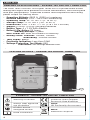 2
2
-
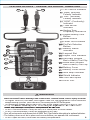 3
3
-
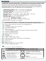 4
4
-
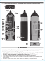 5
5
-
 6
6
-
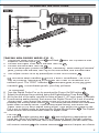 7
7
-
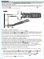 8
8
-
 9
9
-
 10
10
-
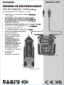 11
11
-
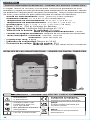 12
12
-
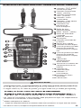 13
13
-
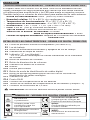 14
14
-
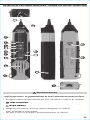 15
15
-
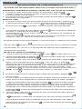 16
16
-
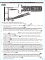 17
17
-
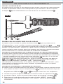 18
18
-
 19
19
-
 20
20
-
 21
21
-
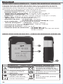 22
22
-
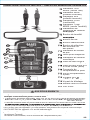 23
23
-
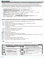 24
24
-
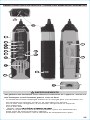 25
25
-
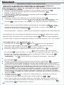 26
26
-
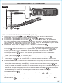 27
27
-
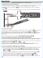 28
28
-
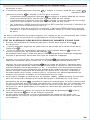 29
29
-
 30
30
-
 31
31
-
 32
32


Klein Tools VDV500-920 Manuel utilisateur
- Catégorie
- Testeurs de réseau câblé
- Taper
- Manuel utilisateur
dans d''autres langues
- English: Klein Tools VDV500-920 User manual
- español: Klein Tools VDV500-920 Manual de usuario
Documents connexes
-
Klein Tools VDV500-063 Manuel utilisateur
-
Klein Tools VDV500-820 Manuel utilisateur
-
-
home KLEIN TOOLS Manuel utilisateur
-
Klein Tools VDV500-705 Mode d'emploi
-
-
-
-
Klein Tools VDV770-850 Manuel utilisateur
-