Festool MFK 700 Manuel utilisateur
- Catégorie
- Outils électroportatifs
- Taper
- Manuel utilisateur
Ce manuel convient également à

474129_004
Instruction manual
Page 6 - 13
IMPORTANT: Read and understand all instructions before
using.
Guide d’utilisation
Page 14 - 23
IMPORTANT: Lire et comprendre toutes les instructions
avant de démarrer les travaux.
Manual de instrucciones
Pagina 24 - 33
IMPORTANTE: Lea y comprende todas las instrucciones
antes de usar.
Instruction manual
Guide d’utilisation
Manual de instrucciones
MFK 700


1.1

1-2
1-3
1-4

6
Safety rules
General safety rules
Read and understand all in-
structions. Failure to follow all instruc-
tions listed below may result in electric
shock, fi re and/or serious personal in-
jury.
SAVE THESE INSTRUCTIONS
1) Work area safety
a) Keep work area clean and well lit. Clut-
tered and dark areas invite accidents.
b) Do not operate power tools in explo-
sive atmospheres, such as in the pres-
ence of fl ammable liquids, gases or dust.
Power tools create sparks which may ignite
the dust or fumes.
c) Keep children and bystanders away
while operating a power tool. Distractions
can cause you to lose control.
2) Electrical safety
a) Power tool plugs must match the out-
let. Never modify the plug in any way. Do
not use any adapter plugs with earthed
(grounded) power tools. Unmodifi ed plugs
and matching outlets will reduce risk of elec-
tric shock.
b) Avoid body contact with earthed or
grounded surfaces such as pipes, radia-
tors, ranges and refrigerators. There is an
increased risk of electric shock if your body is
earthed or grounded.
c) Do not expose power tools to rain or
wet conditions. Water entering a power tool
will increase the risk of electric shock.
d) Do not abuse the cord. Never use the
cord for carrying, pulling or unplugging
the power tool. Keep cord away from
heat, oil, sharp edges or moving parts.
Damaged or entangled cords increase the risk
of electric shock.
e) When operating a power tool outdoors,
use an extension cord suitable for out-
door use. Use of a cord suitable for outdoor
use reduces the risk of electric shock.
3) Personal safety
a) Stay alert, watch what you are doing
and use common sense when operating a
power tool. Do not use a power tool while
you are tired or under the infl uence of
drugs, alcohol or medication. A moment of
inattention while operating power tools may
result in serious personal injury.
b) Use safety equipment. Always wear
eye protection. Safety equipment such as
dust mask, non-skid safety shoes, hard hat,
or hearing protection used for appropriate
conditions will reduce personal injuries.
c) Avoid accidental starting. Ensure the
switch is in the off position before plug-
ging in. Carrying power tools with your fi nger
on the switch or plugging in power tools that
have the switch on invites accidents.
d) Remove any adjusting key or wrench
before turning the power tool on. A wrench
or a key left attached to a rotating part of the
power tool may result in personal injury.
e) Do not overreach. Keep proper foot-
ing and balance at all times. This enables
better control of the power tool in unexpected
situations.
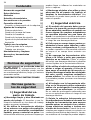
Table of contents
Safety rules 6
Technical data 8
Symbols 8
Scope of delivery 8
Intended use 8
Electrical connection 8
Switching the machine on and off 9
Tool settings 9
Electronic control 9
Changing the router table 9
Changing the routing tool 10
Changing the clamping collet 10
Adjusting the routing depth 11
Dust extraction 11
Working with the machine 11
Machine guidance methods 11
Aluminium processing 12
Service and maintenance 12
Accessories, tools 12
Warranty 13

7
f) Dress properly. Do not wear loose
clothing or jewellery. Keep your hair,
clothing and gloves away from moving
parts. Loose clothes, jewellery or long hair
can be caught in moving parts.
g) If devices are provided for the con-
nection of dust extraction and collection
facilities, ensure these are connected
and properly used. Use of these devices
can reduce dust related hazards.
4) Tool use and care
a) Do not force the power tool. Use the
correct power tool for your application.
The correct power tool will do the job better
and safer at the rate for which it was de-
signed.
b) Do not use the power tool if the switch
does not turn it on and off. Any power tool
that cannot be controlled with the switch is
dangerous and must be repaired.
c) Disconnect the plug from the power
source before making any adjustments,
changing accessories, or storing power
tools. Such preventive safety measures re-
duce the risk of starting the power tool ac-
cidentally.
d) Store idle power tools out of the reach
of children and do not allow persons
unfamiliar with the power tool or these
instructions to operate the power tool.
Power tools are dangerous in the hands of
untrained users.
e) Maintain power tools. Check for mis-
alignment or binding of moving parts,
breakage of parts and any other condi-
tion that may affect the power tools op-
eration. If damaged, have the power tool
repaired before use. Many accidents are
caused by poorly maintained power tools.
f) Keep cutting tools sharp and clean.
Properly maintained cutting tools with sharp
cutting edges are less likely to bind and are
easier to control.
g) Use the power tool, accessories and
tool bits etc., in accordance with these
instructions and in the manner intended
for the particular type of power tool, tak-
ing into account the working conditions
and the work to be performed. Use of
the power tool for operations different from
those intended could result in a hazardous
situation.
5) Service
a) Have your power tool serviced by a
qualifi ed repair person using only identi-
cal replacement parts. This will ensure that
the safety of the power tool is maintained.
Specifi c Safety Rules
a) Hold power tools by insulated gripping
surfaces when performing an operation
where the cutting tool may contact hid-
den wiring or its own cord. Contact with a
”live” wire will make exposed metal parts of
the tool ”live” and shock the operator.
b) Use clamps or another suitable means
to support and secure the workpiece to
a stable platform. Holding the workpiece
by hand or against your body is unstable and
may lead to loss of control.
Health hazard by dust
Various dust created by power
sanding, sawing, grinding, drilling and other
construction activities contains chemicals
known (to the State of California) to cause
cancer, birth defects or other reproductive
harm. Some examples of these chemicals
are:
lead from lead-based paints,•
crystalline silica from bricks and cement •
and other masonry products, and
arsenic and chromium from chemically-•
treated lumber.
The risk from these exposures varies, depend-
ing on how often you do this type of work.
To reduce your exposure to these chem-
icals: work in a well ventilated area, and
work with approved safety equipment,
such as dust masks that are specially
designed to fi lter out microscopic par-
ticles. Wash hands after handling.
TO REDUCE THE RISK OF
INJURY, USER MUST READ AND UNDER-
STAND INSTRUCTION MANUAL.

8
Technical data
Power consumption 720 W
Rotational speed (no load)
10000 - 26000 rpm
Tool holder 8 mm (0.31")
optional: 6 mm (0.24")
1/4"(6.35 mm)
Max. routing tool diameter 26 mm (1")
Weight 1.9 kg (4.2 lbs)
Safety
/II
Symbols
V Volts
A Amperes
Hz Hertz
~ Alternating current
n
0
No load speed
Class II Construction
rpm Revolutions or reciprocation per
minute
Ø Diameter
Warning of general danger
Read the Operating Instructions/
Notes!
f Advice or tip
Scope of delivery
The pictures for the scope of delivery are on a
fold-out page at the beginning of the instruc-
tion manual. When reading of the manual you
can fold out this page for having always an
overview of the machine.
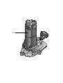
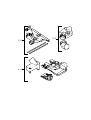
[1-1] MFK 700 with large surface router ta-
ble
[1-2] Side stop with guide rods and fi ne ad-
juster
[1-3] Extraction hood for large surface router
table with extractor connector
[1-4] Router table for edge veneer with feeler
roller and extraction hood (only in SET
scope of delivery)
Intended use
The MFK 700 EQ is designed for routing wood,
plastic and similar materials.
The user shall be responsible
and liable for damages and accidents
resulting from misuse or abuse of this
tool.
Electrical connection
The network voltage must conform to the
voltage indicated on the rating plate. A 16
A safety fuse (for 120 V) or a corresponding
protective circuit-breaker is required.
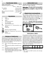
See the following fi gure [2] for connection and
disconnection of the power cable.
Always switch the machine
off before connecting or disconnecting
the power cable!
2
Extension cable
If an extension cable is required, it must have
a suffi cient cross-section so as to prevent an
excessive drop in voltage or overheating. An
excessive drop in voltage reduces the output
and can lead to failure of the motor. The table
below shows you the correct cable diameter as
a function of the cable length for the MFK 700.
Use only U.L. and CSA listed extension cables.
Never use two extension cables together. In-
stead, use one long one.
Total Extension Cord
Lenght (feed)
25 50 100 150
Cord size (AWG) 18 16 16 14
Note:
The lower the AWG number, the stronger f
the cable.

9
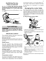
Switching the ma-
chine on and off
Keep the machine steady
during switching and during use by hold-
ing the handles [3-1] [3-2] with both
hands.
The switch [3-4] is an on/off switch (I = ON,
0 = OFF).
3-1
3-3
3-2
3-4
Tool settings
Disconnect the plug from the
power source before making any adjust-
ments, changing accessories, or storing
power tools.
Electronic control
The machine features full-wave electronics
with the following properties:
Smooth start-up
The electronically controlled smooth start-up
function ensures that the machine starts up
smoothly.
Speed control
You can regulate the rotational speed
steplessly between 10000 and 26000 rpm
using the adjusting wheel [3-3]. This enables
you to optimise the cutting speed to suit the
respective material.
Constant speed
The preselected motor speed remains con-
stant through electronic control. This ensures
a uniform cutting speed even when under
strain.
Temperature control
To prevent overheating, the safety electronics
switches the machine off when it reaches a
critical motor temperature. Let the machine
cool down for approx. 3-5 minutes before us-
ing it again. The machine requires less time
to cool down if it is running, i.e. in neutral
position.
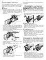
Changing the router table
The “large surface router table” is already fi t-
ted as standard. The large contact surface and
precision adjustment features of this router
table enable a high degree of accuracy. Other
router tables are included in the accessories
programme.
a) Large surface router table
4-2
4-1
2
1
Slide the router table onto the retaining pin –
[4-1] on the machine.
Tighten the screw [4-2] to clamp the router –
table in position.
4-5
4-4
4-3
5
4
3
Place the extraction hood [4-4] in posi- –
tion.
Tighten the screw [4-3] to clamp the ex- –
traction hood in position.
Place the extractor connector [4-5] on the –
extraction hood.
Removal is performed in reverse sequence to
installation.

10
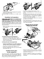
b) Router table for edge veneer
The "router table for edge veneer" (only in SET
scope of delivery) is designed for fl ush trim-
ming veneer overhang and profi le routing.
Notes:
The router table is tilted 1.5° so that the f
surface coating is not damaged during edge
routing. A router table with 0° inclination
angle for precise cuts is available as an
accessory.
5-1
5-2
1
2
Secure the sensor [5-1] to the machine –
using the preassembled screws. Slide the
sensor in the long holes to adjust the rout-
ing tool to the perfect position.
Slide the router table onto the retaining pin –
[5-2] on the machine.
5-3
5-4
3
4
Tighten the screw [5-3] to clamp the router –
table in position.
Place the extraction hood [5-4] in posi- –
tion.
5-5
5
Tighten the screw [5-5] to clamp the ex- –
traction hood in position.
Removal is performed in reverse sequence to
installation.
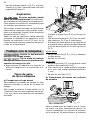
Changing the routing tool
Risk of accident - the routing
tool may be hot after use and has sharp
edges. Allow the tool to cool before chang-
ing. Wear protective gloves when changing
tools.
Remove the router table before changing –
the routing tool.
SW 19
6-2 6-3
6-1
1
2
3
a) Removing the tool
Press the spindle lock [6-1]. –
Unscrew the locking nut [6-2] using the –
open-end wrench (size 19) until you are
able to remove the tool.
b) Inserting the tool
Insert the routing tool [6-3] into the open –
clamping collet as far as possible, but at
least up to the mark (
) on the shank.
Press the spindle lock [6-1]. –
Tighten the locking nut [6-2] using the –
open-end wrench (size 19).
Changing the clamping collet
Only compatible tools can be used in com-
bination with the clamping collets supplied.
8 mm, 6 mm and 1/4" (6.35 mm) clamping
collets can be used.
7-2 7-3
7-1
1
2
3
Press the spindle lock [7-1]. –
Unscrew the locking nut [7-2] completely. –
Remove the locking nut from the spindle –
together with the clamping collet [7-3]. Do
not separate the locking nut and clamping
collet as these form a single component.

11
Attach a different clamping collet with lock- –
ing nut to the spindle.
Screw on the locking nut loosely. Do not –
tighten the locking nut until a router bit is
inserted.
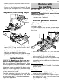
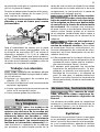
Adjusting the routing depth
8-2
8-3
8-1
1
1
3
3
2
8-38-2
1
3
2
Unscrew the rotary knob [8-3] and the –
clamp [8-1] (“large surface router table”
only).
Turn the rotary wheel [8-2] to set the router –
table to the required routing depth.
Tighten the rotary knob [8-3] and the clamp –
[8-1] (“large surface router table” only).
Dust extraction
Breathing in dust can dam-
age the respiratory passage! Always con-
nect the machine to a dust extractor. When
performing work that generates dust, always
wear a dust mask.
Extraction hoods are supplied for both router
tables; a Festool extractor (extractor hose
with a diameter of 27 mm) can be connected
to these extraction hoods.
The dust extractor (extractor hose with dia.
27 mm) can also be attached to the “large
surface router table” or the side stop depend-
ing on the application.
Working with
the machine
Always hold the machine
with both hands during working.
Always secure the workpiece
in such a manner that it cannot move
while being routed.
Guide the machine along the workpiece at f
a steady rate of advance.
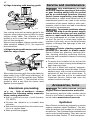
Machine guidance methods
a) Routing with side stop
The side stop is positioned parallel to the
workpiece edge.
The side stop can only be fi tted to the “large
surface router table” without a fi tted extrac-
tion hood.
9-49-3
9-5
9-2
9-1
Insert the fi ne adjuster [9-3] into the side –
stop.
Secure both guide rods [9-5] with the two –
rotary knobs [9-2] on the side stop.
Insert the side stop into the grooves on the –
router table to the required distance and
secure the guide rods by turning the rotary
knob [9-1].
Rough adjustment
Loosen the screws [9-2] and [9-4] and slide –
the side stop.
Tighten the screws. –
Fine adjustment
Loosen the screws [9-2] and turn the green –
wheel on the fi ne adjuster [9-3].
The distance between each line on the ro- f
tary wheel is 0.1 mm - one full turn of the
ring represents 1 mm.
Tighten the screws [9-2]. –

12
b) Edge trimming with bearing guide
10-1
Use routing tools with a bearing guide in the
machine when edge trimming with the large
surface router table. The machine is then
guided in such a way that the bearing guide
rolls off the workpiece.
When trimming edges, always use the under-
table extractor adapter [10-1] for improved
dust extraction.
c) Edge trimming with sensor and router
table for edge veneer
11-1
1,5°
When edge trimming with the router table for
edge veneer (only in SET scope of delivery), fi t
the sensor [11-1] to the machine (see “Router
table for edge veneer “). The machine is then
guided in such a way that the sensor rests
against the workpiece.
Aluminium processing
Risk of accident - always
perform the following safety measures
when routing aluminium:
Add a residual-current circuit-breaker f
(FI, PRCD).
Connect the machine to a suitable dust f
extractor.
Remove dust deposits from the motor hous- f
ing on a regular basis.
Wear protective goggles. f
Service and maintenance
Any maintenance or repair
work that requires opening of the motor
or gear housing should only be carried
out by an authorised Customer Service
Centre (name supplied by your dealer)!
Maintenance or repair work carried out by an
unauthorised person can lead to the wrong
connection of the power leads or other com-
ponents, which in turn can lead to accidents
with serious consequences.
To prevent accidents, always
remove the plug from the power supply
socket before carrying out any mainte-
nance or repair work on the machine! Do
not use compressed air to clean the electri-
cal tool! Do not try to clean parts inside the
machine in this way, as you could let foreign
objects in through the openings of the ma-
chine housing.
Certain cleaning agents and
solvents are harmful to plastic parts.
Some of these are: gasoline, carbonyl chlo-
ride, cleaning solutions containing chlorine,
ammonia and household cleaners containing
ammonia.
To assure the circulation of air, the cool air f
vents in the motor housing must always be
kept clear and clean.
This unit is fi tted with special, automati- f
cally disconnecting carbon brushes. If these
become worn, the current is automatically
switched off and the unit shuts down. In
this case, take the unit to an authorised
Customer Service Centre and have the
carbon brushes changed.
Accessories, tools
For safety reasons, only use
original Festool accessories and tools!
The accessory and tool order number can be
found in the Festool catalogue or on the In-
ternet under www.festool-usa.com.
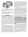
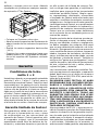
Systainer
Many Festool products are shipped in a unique
system container, called "Systainer". This pro-
vides protection and storage for the tool and
accessories. The Systainers are stackable and
can be interlocked together. They also can be
interlocked atop Festool CT dust extractors.

13
12.1
12.2
12.3
Place one systainer on top of the other. –
Release all four latches on the lower sys- –
tainer by pulling back at their top edges
(12.1).
Slide all four latches upward (12.2). –
Snap all four latches back to their fl at po- –
sition (12.3) so they engage the stacking
tabs of the upper systainer.
Warranty
Conditions of 1+2 Warranty
You are entitled to a free extended warranty
(1 year + 2 years = 3 years) for your Festool
power tool. Festool shall be responsible for
all shipping costs during the fi rst year of the
warranty. During the second and third year of
the warranty the customer is responsible for
shipping the tool to Festool. Festool will pay
for return shipping to the customer using UPS
Ground Service. All warranty service is valid
3 years from the date of purchase on your
receipt or invoice.
Festool Limited Warranty
This warranty is valid on the pre-condition that
the tool is used and operated in compliance
with the Festool operating instructions. Fes-
tool warrants, only to the original consumer
purchaser, that the specifi ed tool will be free
from defects in materials and workmanship
for a term of one year from the date of pro-
curement. Festool makes no other warranty,
express or implied, for Festool portable power
tools. No agent, representative, distributor,
dealer or employee of Festool has the au-
thority to increase or otherwise change the
obligations or limitations of this warranty. The
obligations of Festool in its sole discretion un-
der this warranty shall be limited to the repair
or replacement of any Festool portable power
tool that is found to be defective as packaged
with the User Manual.
Excluded from coverage under this warranty
are: normal wear and tear; damages caused
by misuse, abuse or neglect; damage caused
by anything other than defects in material and
workmanship. This warranty does not apply to
accessory items such as circular saw blades,
drill bits, router bits, jigsaw blades, sanding
belts, and grinding wheels. Also excluded
are “wearing parts”, such as carbon brushes,
lamellas of air tools, rubber collars and seals,
sanding discs and pads, and batteries.
Festool portable power tools requiring replace-
ment or repair are to be returned with the
receipt of purchase to Festool (call 800-554-
8741 for address details).
IN NO EVENT SHALL FESTOOL BE LIABLE
FOR ANY CONSEQUENTIAL OR INCIDEN-
TAL DAMAGES FOR BREACH OF THIS OR
ANY OTHER WARRANTY, EXPRESSED OR
IMPLIED WHATSOEVER. ALL WARRAN-
TIES IMPLIED BY STATE LAW, INCLUD-
ING THE IMPLIED WARRANTIES OF
MERCHANTABILITY AND FITNESS FOR
A PARTICULAR PURPOSE, ARE HEREBY
LIMITED TO THE DURATION OF THREE
YEARS.
Some states in the U.S. and some Canadian
provinces do not allow the limitations on how
long an implied warranty lasts, so the above
limitation may not apply to you. With the ex-
ception of any warranties implied by state or
province law as hereby limited, the foregoing
express limited warranty is exclusive and in
lieu of all other warranties, guarantees, agree-
ments and similar obligations of Festool.
This warranty gives you specifi c legal rights
and you may also have other rights which vary
from state to state in the U.S. and province
to province in Canada.

14
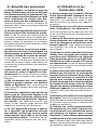
Table des matières
Régles de sécurité
Assurez-vous de lire
et de bien com prendre toutes les ins-
tructions. Le non-respect, même partiel,
des instructions ci-dessous peut entraîner un
risque de choc électrique, d’incendie et/ou de
blessures graves.
CONSERVEZ CES INSTRUCTIONS
Régles de sécu-
rité générales
1) Sécurité de aire de travail
a) Maintenez l’endroit de travail pro-
pre et bien éclairé. Un lieu de travail en
désordre ou mal éclairé augmente le risque
d’accidents.
b) N’utilisez pas l’appareil dans un envi-
ronnement présentant des risques d’ex-
plosion et où se trouvent des liquides,
des gaz ou poussières infl ammables. Les
outils électroportatifs génèrent des étincelles
risquant d’enfl ammer les poussières ou les
vapeurs.
c) Tenez les enfants et autres personnes
éloignés durant l’utilisation de l’outil
électroportatif. En cas d’inattention vous
risquez de perdre le contrôle sur l’appareil.
2) Sécurité électrique
a) La fi che de secteur de l’outil électro-
portatif doit être appropriée à la prise
de courant. Ne modifi ez en aucun cas la
fi che. N’utilisez pas de fi ches d’adapta-
teur avec des appareils avec mise à la
terre. Les fi ches non modifi ées et les prises
de courant appropriées réduisent le risque de
choc électrique.
b) Evitez le contact physique avec des
surfaces mises à la terre tels que tuyaux,
radiateurs, fours et réfrigérateurs. Il y a
un risque élevé de choc électrique au cas où
votre corps serait relié à la terre.
c) N’exposez pas l’outil électroportatif
à la pluie ou à l’humidité. La pénétration
d’eau dans un outil électroportatif augmente
le risque d’un choc électrique.
d) N’utilisez pas le câble à d’autres fi ns
que celles prévues, n’utilisez pas le câble
pour porter l’appareil ou pour l’accro-
cher ou encore pour le débrancher de
la prise de courant. Maintenez le câble
éloigné des sources de chaleur, des par-
ties grasses, des bords tranchants ou des
parties de l’appareil en rotation. Un câble
endommagé ou torsadé augmente le risque
d’un choc électrique.
e) Au cas où vous utiliseriez l’outil élec-
troportatif à l’extérieur, utilisez une
rallonge autorisée homologuée pour les
applications extérieures. L’utilisation d’une
rallonge électrique homologuée pour les ap-
plications extérieures réduit le risque d’un
choc électrique.
f) Ne tenez l‘outil qu‘à l‘aide des poignées
isolées, lorsque vous êtes susceptibles de
toucher des lignes électriques cachées
ou votre propre câble électrique, lorsque
vous travaillez avec des outils de tronçon-
nage. Si des outils de tronçonnage touchent
des lignes électriques, des pièces métalliques
de l‘outil peuvent être mises sous tension et as-
séner une décharge électrique à l‘utilisateur.
Régles de sécurité 14
Caractéristiques techniques 16
Symboles 16
Eléments fournis 17
Utilisation conforme aux
prescriptions 17
Raccordement électrique 17
Mise en marche et arrêt de la machine 17
Réglages de la machine 18
Système électronique 18
Remplacement de la table de fraisage 18
Changement de fraise 19
Changement de pince de serrage 19
Réglage de la profondeur de fraisage 20
Aspiration 20
Travail avec la machine 20
Types de guidage de la machine 20
Usinage de l'aluminium 21
Maintenance et entretien 21
Accessoires, outils 21
Garantie 22

15
3) Sécurité des personnes
a) Restez vigilant, surveillez ce que vous
faites. Faites preuve de bon en utilisant
l’outil électroportatif. N’utilisez pas l’ap-
pareil lorsque vous êtes fatigué ou après
avoir consommé de l’alcool, des dro-
gues ou avoir pris des médicaments. Un
moment d’inattention lors de l’utilisation de
l’appareil peut entraîner de graves blessures
sur les personnes.
b) Portez des équipements de protection.
Portez toujours des lunettes de protec-
tion. Le fait de porter des équipements de
protection personnels tels que masque anti-
poussières, chaussures de sécurité antidéra-
pantes, casque de protection ou protection
acoustique suivant le travail à effectuer, réduit
le risque de blessures.
c) Evitez une mise en service par mégar-
de. Assurez-vous que l’interrupteur est
effectivement en position d’arrêt avant
de retirer la fi che de la prise de courant.
Le fait de porter l’appareil avec le doigt sur
l’interrupteur ou de brancher l’appareil sur la
source de courant lorsque l’interrupteur est
en position de fonctionnement, peut entraîner
des accidents.
d) Enlevez tout outil de réglage ou toute
clé avant de mettre l’appareil en fonc-
tionnement. Une clé ou un outil se trouvant
sur une partie en rotation peut causer des
blessures.
e) Ne surestimez pas vos capacités.
Veillez à garder toujours une position
stable et équilibrée. Ceci vous permet de
mieux contrôler l’appareil dans des situations
inattendues.
f) Portez des vêtements appropriés. Ne
portez pas de vêtements amples ni de
bijoux. Maintenez cheveux, vêtements et
gants éloignés des parties de l’appareil
en rotation. Des vêtements amples, des
bijoux ou des cheveux longs peuvent être
happés par des pièces en mouvement.
g) Si des dispositifs servant à aspirer
ou à recueillir les poussières doivent
être utilisés, vérifi ez que ceux-ci soient
effectivement raccordés et qu’ils sont
correctement utilisés. L’utilisation de tels
dispositifs réduit les dangers dus aux pous-
sières.
4) Utilisation et en-
tretien des outils
a) Ne surchargez pas l’appareil. Utilisez
l’outil électroportatif approprié au tra-
vail à effectuer. Avec l’outil électroportatif
approprié, vous travaillerez mieux et avec
plus de sécurité à la vitesse pour laquelle il
est prévu.
b) N’utilisez pas un outil électroportatif
dont l’interrupteur est défectueux. Un
outil électroportatif qui ne peut plus être mis
en ou hors fonctionnement est dangereux et
doit être réparé.
c) Retirer la fi che de la prise de courant
avant d’effectuer des réglages sur l’ap-
pareil, de changer les accessoires, ou de
ranger l’appareil. Cette mesure de précau-
tion empêche une mise en fonctionnement
par mégarde.
d) Gardez les outils électroportatifs non
utilisés hors de portée des enfants. Ne
permettez pas l’utilisation de l’appareil
à des personnes qui ne se sont pas fami-
liarisées avec celui-ci ou qui n’ont pas lu
ces instructions. Les outils électroportatifs
sont dangereux lorsqu’ils sont utilisés par des
personnes non initiées.
e) Prenez soin des outils électroportatifs.
Vérifi ez que les parties en mouvement
fonctionnent correctement et qu’elles ne
soient pas coincées, et contrôlez si des
parties sont cassées ou endommagées
de telle sorte que le bon fonctionnement
de l’appareil s’en trouve entravé. Faites
réparer les parties endommagées avant
d’utiliser l’appareil. De nombreux accidents
sont dus à des outils électroportatifs mal en-
tretenus.
f) Maintenez les outils de coupe aiguisés
et propres. Des outils soigneusement entre-
tenus avec des bords tranchants bien aiguisés
se coincent moins souvent et peuvent être
guidés plus facilement.
g) Utilisez les outils électroportatifs,
les accessoires, les outils à monter etc.
conformément à ces instructions et aux
prescriptions en vigueur pour ce type
d’appareil. Tenez compte également des
conditions de travail et du travail à effec-
tuer. L’utilisation des outils électroportatifs à
d’autres fi ns que celles prévues peut entraîner
des situations dangereuses.

16
5) Entretien et réparation
a) Ne faites réparer votre outil électro-
portatif que par un personnel qualifi é et
seulement avec des pièces de rechange
d’origine. Ceci permet d’assurer la sécurité
de l’appareil.
Règle de sécurité parti-
culière supplémentaire
a) Tenez l’outil par ses surfaces de prise
isolées pendant toute opération où l’outil
de coupe pourrait venir en contact avec
un câblage dissimulé ou avec son propre
cordon. En cas de contact avec un conduc-
teur sous tension, les pièces métalliques à
découvert de l’outil transmettraient un choc
électrique à l’utilisateur.
b) Immobilisez l’outil sur une surface
stable au moyen de brides ou de toute
autre façon adéquate. Le fait de tenir la
pièce avec la main ou contre votre corps offre
une stabilité insuffi sante et peut amener un
dérapage de l’outil.
La poussière, un ris-
que pour la santé
Certaines poussières
créées par le ponçage mécanique, le sciage,
le meulage, le perçage et autres activités re-
liées à la construction contiennent des subs-
tances chimiques connues (dans l’État de la
Californie) comme pouvant causer le cancer,
des anomalies congénitales ou représenter
d’autres dangers pour la reproduction. Voici
quelques exemples de telles substances:
plomb provenant de peintures à base de •
plomb,
silice cristallisée utilisée dans les briques, •
le ciment et autres matériaux de maçon-
nerie, et
arsenic et chrome du bois d’œuvre traité •
avec un produit chimique.
Le risque d’exposition à de tels produits varie
selon la fréquence à laquelle vous faites ce
genre de travail.
Pour réduire les risques d’exposition à
ces substances chimiques : travaillez
dans un endroit adéquatement ventilé
et utilisez un équipement de sécurité
approuvé, tel que masques antipoussiè-
res spécialement conçus pour fi ltrer les
particules microscopiques.
POUR RÉDUIRE LE
RISQUE DE DOMMAGES, L'UTILISATEUR
DOIT LIRE ET COMPRENDRE LE MANUEL
D'INSTRUCTION.
Caractéristiques
techniques
Puissance absorbée 720 W
Vitesse de rotation (à vide)
10000 - 26000 min
-1
Porte-outil 8 mm (0.31”)
option : 6 mm, (0.24”)
1/4”(6.35 mm))
Diamètre de fraise, max. 26 mm (1”)
Poids 1,9 kg (4.2 lbs)
Sécurité
/II
Symboles
V Volts
A Ampères
Hz Hertz
~ Courant alternatif
n
0
Vitesse à vide
Construction de classe II
tr/mn Nombre de tours par minute
Ø diamètre
Avertissement de danger général
Lire les instructions / les remarques !
f Information, astuce

17
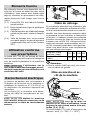
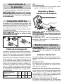
2
Câble de rallonge
Si une rallonge électrique est nécessaire, elle
doit présenter une section suffi sante afi n d’évi-
ter une chute de tension excessive ou une sur-
chauffe. Une chute de tension excessive réduit
la puissance et peut entraîner la destruction
du moteur. Le tableau suivant vous présente
la section correcte du câble en fonction de sa
longueur pour la MFK 700. Utilisez exclusive-
ment des rallonges recommandées par U.L.
et CSA. N’utilisez jamais deux rallonges bran-
chées l’une après l’autre, mais remplacez-les
par une rallonge plus longue.
Longueur totale
rallonge (pieds)
25 50 100 150
Section du câble
(AWG)
18 16 16 14
Remarque:
Plus le numéro AWG est petit, plus la sec- f
tion du câble est grande.
Mise en marche et ar-
rêt de la machine
3-1
3-3
3-2
3-4
Lors de la mise en
marche et en cours d’utilisation, tenez
toujours la scie à deux mains à les poi-
gnées [3-1] [3-2].
Le commutateur [3-4] sert d'interrupteur de
marche / arrêt (I = "ON", 0 = "OFF").
Eléments fournis
Des eléments fournis sont disponibles sur le
volet qui se trouve au début de cette notice
d'utilisation. Vous pouvez ainsi déplier cette
page et visualiser en permanence les diffé-
rentes parties de l'outil lorsque vous lisez la
notice.
[1-1] Fraise MFK 700 avec table de fraisage
grande surface
[1-2] Butée latérale avec tiges de guidage et
réglage fi n
[1-3] Capot d'aspiration pour table de fraisage
grande surface avec tubulure d'aspira-
tion
[1-4] Table de fraisage pour couvre-chants
avec galet palpeur et capot d'aspiration
(uniquement dans volume de livraison
SET)
Utilisation conforme
aux prescriptions
La fraise MFK 700 EQ est prévue de façon
conforme aux prescriptions pour le fraisage de
bois, de matières plastiques et de matériaux
similaires.
L'utilisateur est le
seul responsable des dommages et acci-
dents provoqués par une utilisation non
conforme de l'outil.
Raccordement électrique
La tension du secteur doit correspondre à
l’indication de la tension sur la plaquette si-
gnalétique. Un fusible de 16 A (à 120 V) ou
un disjoncteur de puissance approprié est
nécessaire.
Voir en fi gure [2] la connexion et la décon-
nexion du câble de raccordement au sec-
teur.
Mettez la machine
hors marche, avant de connexion ou de
déconnexion le câble de raccordement
secteur.

18
Réglages de la machine
Retirer la fi che de la
prise de courant avant d‘effectuer des
réglages sur l‘appareil, de changer les
accessoires, ou de ranger l‘appareil.
Système électronique
Cette machine dispose d'une électronique
complète qui présente les caractéristiques
suivantes :
Démarrage progressif
Le démarrage progressif à régulation électro-
nique assure un démarrage sans à-coups de
la machine.
Régulation de la vitesse
La vitesse de rotation peut être réglée en
continu au moyen de la molette [3-3], entre
10000 et 26000 min
-1
. Vous pouvez ainsi
adapter de façon optimale la vitesse de coupe
à chaque matériau.
Vitesse de rotation constante
La vitesse sélectionnée est maintenue
constante de manière électronique. Elle reste
donc homogène, même lorsque l'outil est
fortement sollicité.
Protection thermique
Pour assurer une protection contre la sur-
chauffe, le système électronique de sécurité
arrête la machine dès qu’une température
critique du moteur est atteinte. Après une pé-
riode de refroidissement d’env. 3 à 5 minutes,
la machine est à nouveau prête à l’emploi. Le
temps de refroidissement diminue quand la
machine fonctionne (marche à vide).
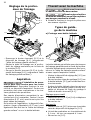
Remplacement de la ta-
ble de fraisage
La "table de fraisage grande surface" est
prémontée et comprise dans le volume de
livraison de série. Cette table de fraisage ga-
rantit une grande précision de fraisage grâce
à sa grande surface d'appui et à ses possi-
bilités de réglage précises. D'autres tables
de fraisage sont disponibles dans la gamme
d'accessoires.
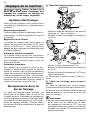
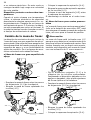
a) Table de fraisage grande surface
4-2
4-1
2
1
Montez la table de fraisage sur les axes de –
réception [4-1] de la machine.
Bloquez la table de fraisage en serrant la –
vis [4-2].
4-5
4-4
4-3
5
4
3
Montez le capot d'aspiration [4-4]. –
Bloquez le capot d'aspiration en vissant la –
vis [4-3].
Montez la tubulure d'aspiration [4-5] sur le –
capot d'aspiration.
Le démontage s'effectue dans l'ordre in-
verse.
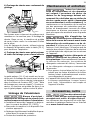
b) Table de fraisage pour couvre-
chants
La "table de fraisage pour couvre-chants"
(uniquement dans le volume de livraison SET)
est prévue pour le fraisage d'affl eurement de
dépassements de couvre-chants ainsi que
pour le profi lage.
Remarque:
Afi n de ne pas endommager le revêtement f
de la table lors de l'affl eurage, la table
de fraisage est inclinée de 1,5°. Pour des
fraisages à angle droit précis, une table de
fraisage non inclinée (0°) est disponible en
tant qu'accessoire.

19
5-1
5-2
1
2
Fixez le galet palpeur [5-1] sur la machine –
à l'aide des vis prémontées. Le galet pal-
peur peut être réglé de façon optimale par
rapport à la fraise en le décalant dans les
trous oblongs.
Montez la table de fraisage sur les axes de –
réception [5-2] de la machine.
5-3
5-4
3
4
Bloquez la table de fraisage en serrant la –
vis [5-3].
Montez le capot d'aspiration [5-4]. –
5-5
5
Bloquez le capot d'aspiration en vissant la –
vis [5-5].
Le démontage s'effectue dans l'ordre in-
verse.
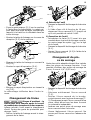
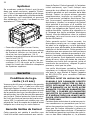
Changement de fraise
Risque d'accident - la
fraise peut être chaude après le travail
et possède des tranchants très coupants.
Laissez refroidir l'outil avant le changement
d'outil. Portez des gants de protection pour
changer l'outil.
Retirez la table de fraisage avant le chan- –
gement de la fraise.
SW 19
6-2 6-3
6-1
1
2
3
a) Retrait de l'outil
Pressez le dispositif de blocage de la broche –
[6-1].
A l'aide d'une clé à fourche de 19 mm, –
desserrez l'écrou-raccord [6-2] jusqu'à ce
qu'il soit possible de retirer l'outil.
b) Insertion de l'outil
Introduisez la fraise [6-3] aussi loin que –
possible dans la pince de serrage ouverte,
au moins jusqu'au repère (
) sur la tige
de la fraise.
Pressez le dispositif de blocage de la broche –
[6-1].
Serrez l'écrou-raccord [6-2] à l'aide de la –
clé à fourche de 19.
Changement de pin-
ce de serrage
Seuls des outils adaptés doivent être insérés
dans les pinces de serrage fournies. Il est
possible d'utiliser des pinces de serrage de
8 mm, 6 mm et 1/4” (6,35 mm).
7-2 7-3
7-1
1
2
3
Pressez le dispositif de blocage de la broche –
[7-1].
Dévissez entièrement l'écrou-raccord –
[7-2].
Retirez l'écrou-raccord de la broche, –
conjointement avec la pince de serrage [7-
3]. Ne séparez jamais l'écrou-raccord de sa
pince, étant donné que les deux forment
un ensemble inséparable.
Insérez une autre pince de serrage avec –
écrou-raccord dans la broche.
Vissez légèrement l'écrou-raccord. Ne –
serrez pas l'écrou-raccord en l'absence de
fraise.

20
Réglage de la profon-
deur de fraisage
8-2
8-3
8-1
1
1
3
3
2
8-38-2
1
3
2
Desserrez le bouton tournant [8-3] et le –
dispositif de blocage [8-1] (uniquement
"table de fraisage grande surface").
Réglez la table de fraisage sur la profon- –
deur de réglage souhaitée par le biais de
la molette [8-2].
Serrez le bouton tournant [8-3] et le dis- –
positif de blocage [8-1] (uniquement "table
de fraisage grande surface").
Aspiration
L'inhalation de pous-
sières peut être nocive pour les voies
respiratoires ! Raccordez toujours la ma-
chine à un dispositif d'aspiration. Portez une
protection des voies respiratoires si les tra-
vaux génèrent des poussières.
Des capots d'aspiration permettant le rac-
cordement d'un aspirateur Festool (tuyau
d'aspiration Ø 27 mm) sont fournis pour les
deux tables de fraisage.
En fonction de l'application, le dispositif d'as-
piration (tuyau d'aspiration Ø
27 mm) peut
également être fi xé sur la "table de fraisage
grande surface" ou sur la butée latérale.
Travail avec la machine
Maintenez fermement
la machine avec les deux mains.
Fixez toujours la pièce
à fraiser de manière à ce qu'elle ne puisse
pas bouger pendant le travail.
Guidez la machine le long de la pièce avec f
une avance régulière.
Types de guida-
ge de la machine
a) Fraisage avec butée latérale
9-49-3
9-5
9-2
9-1
La butée latérale est utilisée pour des travaux
de fraisage parallèlement au bord de la pièce.
La butée latérale peut uniquement être mon-
tée sur la "table de fraisage grande surface"
et sans capot d'aspiration monté.
Montez le dispositif de réglage fi n [9-3] sur –
la butée latérale.
Serrez les deux tiges de guidage [9-5] sur –
la butée latérale [9-2] par le biais des bou-
tons tournants.
Insérez la butée latérale dans les rainures –
de la table de fraisage jusqu'à la cote sou-
haitée et bloquez les tiges de guidage à
l'aide du bouton tournant [9-1].
Réglage approximatif
Desserrez les vis [9-2] et [9-4] et déplacez –
la butée latérale.
Serrez les vis. –
Réglage fi n
Desserrez les vis [9-2] et tournez la molette –
verte du dispositif de réglage fi n [9-3].
Un trait de graduation sur la molette est de f
0,1 mm - un tour correspond à 1 mm.
Serrez les vis [9-2]. –
La page est en cours de chargement...
La page est en cours de chargement...
La page est en cours de chargement...
La page est en cours de chargement...
La page est en cours de chargement...
La page est en cours de chargement...
La page est en cours de chargement...
La page est en cours de chargement...
La page est en cours de chargement...
La page est en cours de chargement...
La page est en cours de chargement...
La page est en cours de chargement...
La page est en cours de chargement...
La page est en cours de chargement...
La page est en cours de chargement...
La page est en cours de chargement...
La page est en cours de chargement...
La page est en cours de chargement...
-
 1
1
-
 2
2
-
 3
3
-
 4
4
-
 5
5
-
 6
6
-
 7
7
-
 8
8
-
 9
9
-
 10
10
-
 11
11
-
 12
12
-
 13
13
-
 14
14
-
 15
15
-
 16
16
-
 17
17
-
 18
18
-
 19
19
-
 20
20
-
 21
21
-
 22
22
-
 23
23
-
 24
24
-
 25
25
-
 26
26
-
 27
27
-
 28
28
-
 29
29
-
 30
30
-
 31
31
-
 32
32
-
 33
33
-
 34
34
-
 35
35
-
 36
36
-
 37
37
-
 38
38


Festool MFK 700 Manuel utilisateur
- Catégorie
- Outils électroportatifs
- Taper
- Manuel utilisateur
- Ce manuel convient également à
dans d''autres langues
- English: Festool MFK 700 User manual
- español: Festool MFK 700 Manual de usuario
Documents connexes
-
Festool PAC574354 Manuel utilisateur
-
Festool OF 1010 EQ Manuel utilisateur
-
-
-
Festool MFK 700 EQ-Set Mode d'emploi
-
-
Festool PN574342 Manuel utilisateur
-
-
Festool 574453 Mode d'emploi

