Miller ADI 253 Le manuel du propriétaire
- Catégorie
- Système de soudage
- Taper
- Le manuel du propriétaire
Ce manuel convient également à

Miller
The
Power
fBlue.
OM-2217
April
1997
En.
w/SeriaI
Number
KH384382
Processes
TIG
(GTAW)
Welding
Stick
(SMAW)
Welding
0
Description
Arc
Welding
Power
Source
~
fllli~Gk~1
7J~
TM
Visit
our
website
at
www.m~e~weIds.com
OWNERS
MANUAL

Thank
you
and
congratulations
on
choosing
Miller.
Now
you
can
get
the
job
done
and
get
it
done
right.
We
know
you
dont
have
time
to
do
it
any
other
way.
Thats
why
when
Neils
Miller
first
started
building
arc
welders
in
1929,
he
made
sure
his
products
offered
long-lasting
value
and
superior
quality.
Like
you,
his
customers
couldnt
afford
anything
less.
Miller
products
had
to
be
more
than
the
best
they
could
be.
They
had
to
be
the
best
you
could
buy.
Today,
the
people
that
build
and
sell
Miller
products
continue
the
tradition.
Theyre
just
as
conmiitted
to
providing
equipment
and
service
that
meets
the
high
standards
of
quality
and
value
established
in
1929.
This
Owners
Manual
is
designed
to
help
you
get
the
most
out
of
your
Miller
products.
Please
take
time
to
read
the
Safety
precautions.
They
will
help
you
protect
yourself
against
potential
hazards
on
the
worksite.
Weve
made
installation
and
operation
quick
and
easy.
With
Miller
you
can
count
on
years
of
reliable
service
with
proper
maintenance.
And
if
for
______________
some
reason
the
unit
needs
repair,
theres
a
Troubleshooting
section
that
will
help
you
figure
out
what
the
problem
is.
The
parts
list
will
then
help
you
to
decide
which
exact
part
you
may
need
to
fix
the
problem.
Warranty
and
service
information
for
your
particular
model
are
also
provided.
Miller
Electric
manufactures
a
full
line
of
welders
and
welding
related
equipment.
For
information
on
other
quality
Miller
products,
contact
your
local
Miller
distributor
to
receive
the
latest
full
line
catalog
or
individual
catalog
sheets.
To
locate
your
nearest
distributor
call
1-800-4-A-Miller.
From
to
You
11~iIJIIIII
Ir
REGISTERED
QUALITY
SYSTEM
Miller
is
the
first
weldiNg
equipment
manufacturer
in
the
U.S.A.
to
be
registered
to
the
ISO
9001
Quality
System
Standard.
~?ft~JR~ft1ll1?
Working
as
hard
as
you
do
every
power
source
from
Miller
Is
backed
by
the
most
hassle-free
warranty
in
the
business.
f//A
MHIer
The
Power
?fBlue.

TM
Description
The
ADl~
253
combines
the
advantages
of
inverter
based
power
with
the
built-in
features
and
technology
of
a
high-end
TIG
machine.
At
only
90
lbs.
(40.7
Kg),
the
ADI
253
gives
you
the
portability
to
easily
take
it
anywhere
its
needed.
Plus,
it
can
operate
oft
either
single-
or
three-phase
power.
The
unique
AutoLirikfi
feature
automatically
links
the
power
source
to
the
primary
input
voltage.
The
AOl
253
is
available
for
superior
AC/DC
TIG
(GTAW)
and
Stick
(SMAW)
welding.
300
amps
maximum
output,
250
amps
at
40%
duty
cycle
Dig/Arc
force
control
NEMA
Class
1
rating
HF
Lift
ArcTM
starting
for
AC
and
DC
TIG
(GTAW)
Fan-On-Demand~
operates
the
cooling
system
only
when
needed
lOft(3m)powercord
MILLERS
True
Bluefi
3
year
warranty
Product
features
and
specifications
are
subject
to
change
without
notice
Processes
TIG
(GTAW)
Welding
Call
1
-800-4-A-MILLER
for
your
local
Miller
distributor.
Your
distributor
gives
you
Service
You
always
get
the
fast,
reliable
response
you
need.
Most
replacement
parts
can
be
in
your
hands
in
24
hours.
Support
Need
fast
answers
to
the
tough
welding
questions?
Contact
your
distributor.
The
expertise
of
the
distributor
and
Miller
is
there
to
help
you,
every
step
of
the
way.
Stick
(SMAW)
Welding
The
following
terms
are
used
interchangeably
throughout
this
manual:
TIG
=
GTAW
Stick
=
SMAW
Miller
offers
a
Technical
Manual
15
which
provides
more
detailed
se,vice
and
parts
information
for
your
unit.
To
obtain
a
Technical
Manual,
contact
your
local
distributo,
Your
distributor
can
also
supply
you
~wTh
Welding
Process
Manuals
such
as
SMAW,
GTAW,
GMAW,
and
GMAW-P
For
practical
information
on
weld
ing,
process
applications,
and
Miller
products,
visit
our
website
at
Features
1
Table
of
Contents
Section
.
:
:
Page
1.
Safety
Precautions
2.
Introduction
9
3.
Operation
4.
Maintenance
and
Troubleshooting
18
5.
Electrical
Diagram
22
6.
Parts
List
.24
Options
and
Accessories
Warranty
www.n~erwe~Is.com


1.
Safety
Precautions
Read
Before
Using
111
SymbOl
Usage
4A
Means
Warning!
Watch
Out!
There
are
possible
hazards
with
this
procedure!
The
possible
hazards
are
shown
in
the
adjoining
symbols.
A
Marks
a
special
safety
message.
~
Means
Note;
not
safety
related.
1
2
Arc
Welding
Hazards
A
The
symbols
shown
below
are
used
throughout
this
manual
to
call
attention
to
and
identify
possible
hazards.
When
you
see
the
symbol,
watch
out,
and
follow
the
related
instructions
to
avoid
the
hazard.
The
safety
information
given
below
is
only
a
summary
of
the
more
complete
safety
information
found
in
the
Safety
Standards
listed
in
Section
1.4.
Read
and
follow
all
Safety
Standards.
A
Only
qualified
persons
should
install,
operate,
maintain,
and
repair
this
unit.
A
During
operation,
keep
everybody,
especially
children,
away.
Touching
live
electrical
parts
can
cause
fatal
shocks
or
severe
bums.
The
electrode
and
work
circuit
is
electrically
live
whenever
the
output
is
on.
The
input
power
circuit
and
machine
internal
circuits
are
also
live
when
power
is
on.
In
semiautomatic
or
automatic
wire
welding,
the
wire,
wire
reel,
drive
roll
housing,
and
all
metal
parts
touching
the
welding
wire
are
electrically
live.
Incorrectly
installed
or
improperly
grounded
equipment
is
a
hazard.
Do
not
touch
live
electrical
parts.
Wear
dry,
hole-free
insulating
gloves
and
body
protection.
Insulate
yourself
from
work
and
ground
using
dry
insulating
mats
or
covers
big
enough
to
prevent
any
physical
contact
with
the
work
or
ground.
Do
not
use
AC
output
in
damp
areas,
if
movement
is
confined,
or
if
there
is
a
danger
of
falling.
Use
AC
output
ONLY
if
required
for
the
welding
process.
If
AC
output
is
required,
use
remote
output
control
if
present
on
unit.
Disconnect
input
power
or
stop
engine
before
installing
or
servicing
this
equipment.
Lockout/tagout
input
power
according
to
OSFIA
29
CFR
191
0.147
(see
Safety
Standards).
Properly
install
and
ground
this
equipment
according
to
its
Owners
Manual
and
national,
state,
and
local
codes.
Always
verify
the
supply
ground
check
and
be
sure
that
input
power
cord
ground
wire
is
properly
connected
to
ground
terminal
in
disconnect
box
or
that
cord
plug
is
connected
to
a
properiy
grounded
receptacle
outlet.
When
making
input
connections,
attach
proper
grounding
conductor
first
double-check
connections.
Frequently
inspect
input
power
cord
for
damage
or
bare
wiring
replace
cord
immediately
if
damaged
bare
wiring
can
kill.
Turn
oft
all
equipment
when
not
in
use.
Do
not
use
worn,
damaged,
undersized,
or
pooriy
spliced
cables.
This
group
of
symbols
means
Warning!
Watch
Out!
possible
ELECTRIC
SHOCK,
MOVING
PARTS,
and
HOT
PARTS
hazards.
Consult
symbols
and
related
instructions
below
for
necessary
actions
to
avoid
the
hazards.
Do
not
drape
cables
over
your
body.
If
earth
grounding
of
the
workpiece
is
required,
ground
it
directly
with
a
separate
cable
do
not
use
work
clamp
or
work
cable.
Do
not
touch
electrode
if
you
are
in
contact
with
the
work,
ground,
or
another
electrode
from
a
difterent
machine.
Use
only
well-maintained
equipment.
Repairor
replace
damaged
parts
at
once.
Maintain
unit
according
to
manual.
Wear
a
safety
harness
if
working
above
floor
level.
Keep
all
panels
and
covers
securely
in
place.
Clamp
work
cable
with
good
metal-to-metal
contact
to
workpiece
or
worktable
as near
the
weld
as
practical.
Insulate
work
clamp
when
not
connected
to
workpiece
to
prevent
contact
with
any
metal
object.
SIGNIFICANT
DC
VOLTAGE
exists
after
removal
of
input
power
on
inverters.
Turn
Off
inverter,
disconnect
input
power,
and
discharge
input
capacitors
according
to
instructions
in
Maintenance
Section
before
touching
any
parts.
FUMES
ANDGASES
can
be
hazardous.
Welding
produces
fumes
and
gases.
Breathing
these
fumes
and
gases
can
be
hazardous
to
your
health.
Keep
your
head
out
of
the
fumes.
Do
not
breathe
the
fumes.
If
inside,
ventilate
the
area
and/or
use
exhaust
at
the
arc
to
remove
welding
fumes
and
gases.
If
ventilation
is
poor,
use
an
approved
air-supplied
respirator.
Read
the
Material
Safety
Data
Sheets
(MSDSs)
and
the
manufacturers
instructions
for
metals,
consumables,
coatings,
cleaners,
and
degreasers.
Work
in
a
confined
space
only
if
it
is
well
ventilated,
or
while
wearing
an
air-supplied
respirator.
Always
have
a
trained
watch-
person
nearby.
Welding
fumes
and
gases
can
displace
air
and
lower
the
oxygen
level
causing
injury
or
death.
Be
sure
the
breathing
air
is
safe.
Do
not
weld
in
locations
near
degreasing,
cleaning,
or
spraying
operations.
The
heat
and
rays
of
the
arc
cart
react
with
vapors
to
form
highly
toxic
and
irritating
gases.
Do
not
weld
on
coated
metals,
such
as
galvanized,
lead,
or
cadmium
plated
steel,
unless
the
coating
is
removed
from
the
weld
area,
the
area
is
well
ventilated,
and
if
necessary,
while
wearing
an
air-supplied
respirator.
The
coatings
and
any
metals
containing
these
elements
can
give
oft
toxic
fumes
if
welded.
OM-2217
-
Date,
safety_corn
4197
ELECTRIC
SHOCK
can
kill.
OM-221
7
1

ARC
RAYS
can
burn
eyes
and
skin
Arc
rays
from
the
welding
process
produce
intense
visible
and
invisible
(ultraviolet
and
infrared)
rays
that
can
bum
eyes
and
skin.
Sparks
fly
oft
from
the
weld.
Wear
a
welding
helmet
fitted
with
a
proper
shade
of
filter
to
protect
your
face
and
eyes
when
welding
or
watching
(see
ANSI
Z49.1
and
Z87.1
listed
in
Safety
Standards).
Wear
approved
safety
glasses
with
side
shields
under
your
helmet.
Use
protective
screens
or
barriers
to
protect
others
from
flash
and
glare;
wam
others
not
to
watch
the
arc.
Wear
protective
clothing
made
from
durable,
flame-resistant
matenal
(leather
and
wool)
and
foot
protection.
WELDING
can
causefireorexplosion.
Welding
on
closed
containers,
such
as
tanks,
drums,
or
pipes,
can
cause
them
to
blow
up.
Sparks
can
fly
off
from
the
welding
arc.
The
flying
sparks,
hot
workpiece,
and
hot
equipment
can
cause
fires
and
burns.
Accidental
contact
of
electrode
to
metal
objects
can
cause
sparks,
explosion,
overheating,
or
fire.
Check
and
be
sure
the
area
is
safe
before
doing
any
welding.
Protect
yourself
and
others
from
flying
sparks
and
hot
metal.
Do
not
weld
where
flying
sparks
can
strike
flammable
material.
Remove
all
flammables
within
35
ft
(10.7
m)
of
the
welding
arc.
If
this
is
not
possible,
tightly
cover
them
with
approved
covers.
Be
alert
that
welding
sparks
and
hot
materials
from
welding
can
easily
go
through
small
cracks
and
openings
to
adjacent
areas.
Watch
for
fire,
and
keep
a
fire
extinguisher
nearby.
Be
aware
that
welding
on
a
ceiling,
floor,
bulkhead,
or
partition
can
cause
fire
on
the
hidden
side.
Do
not
weld
on
closed
containers
such
as
tanks,
drums,
or
pipes,
unless
they
are
properly
prepared
according
to
AWS
F4.i
(see
Safety
Standards).
Connect
work
cable
to
the
work
as
close
to
the
welding
area
as
practical
to
prevent
welding
current
from
traveling
long,
possibly
unknown
paths
and
causing
electric
shock
and
fire
hazards.
Do
not
use
welder
to
thaw
frozen
pipes.
Remove
stick
electrode
from
holder
or
cut
off
welding
wire
at
contact
tip
when
not
in
use.
Wear
oil-free
protective
garments
such
as
leather
gloves,
heavy
shirt,
cuffless
trousers,
high
shoes,
and
a
cap.
Remove
any
combustibles,
such
as
a
butane
lighter
or
matches,
from
your
person
before
doing
any
welding.
FLYING
METALcan
injure
eyes.
Welding,
chipping,
wire
brushing,
and
grinding
cause
sparks
and
flying
metal.
As
welds
cool,
they
can
throw
oft
slag.
Wear
approved
safety
glasses
with
side
shields
even
under
your
welding
helmet.
BUILDUP
OF
GAS
can
injure
or
kill
Shut
off
shielding
gas
supply
when
not
in
use.
Always
ventilate
confined
spaces
or
use
approved
air-supplied
respirator.
HOT
PARTS
can
causesevere
burns..
Do
not
touch
hot
parts
bare
handed.
Allow
cooling
period
before
working
on
gun
or
torch.
MAGNETIC
FIELDS
can
affect
pacemakers..
Pacemaker
wearers
keep
away.
Wearers
should
consult
their
doctor
before
going
near
arc
welding,
gouging,
or
spot
welding
operations.
NOISE
can
damage
hearing.
Noise
from
some
processes
or
equipment
can
damage
hearing.
Wear
approved
ear
protection
if
noise
level
is
high.
CYLINDERS
can
explode
if
damaged.
Shielding
gas
cylinders
contain
gas
under
high
pressure.
If
damaged,
a
cylinder
can
explode.
Since
gas
cylinders
are
normally
part
of
the
welding
process,
be
sure
to
treat
them
carefully.
Protect
compressed
gas
cylinders
from
excessive
heat,
mechanical
shocks,
slag,
open
flames,
sparks,
and
arcs.
Install
cylinders
in
an
upright
position
by
securing
to
a
stationary
support
or
cylinder
rack
to
prevent
falling
or
tipping.
Keep
cylinders
away
from
any
welding
or
other
electrical
circuits.
Never
drape
a
welding
torch
over
a
gas
cylinder.
Never
allow
a
welding
electrode
to
touch
any
cylinder.
Never
weld
on a
pressurized
cylinder
explosion
will
result.
Use
only
correct
shielding
gas
cylinders,
regulators,
hoses,
and
fittings
designed
for
the
specific
application;
maintain
them
and
associated
parts
in
good
condition.
Turn
face
away
from
valve
outlet
when
opening
cylinder
valve.
Keep
protective
cap
in
place
overvalve
except
when
cylinder
is
in
use
or
connected
for
use.
Read
and
follow
instructions
on
compressed
gas
cylinders,
associated
equipment,
and
CGA
publication
P-i
listed
in
Safety
Standards.
2
OM-22i
7

-
FIRE
OR
EXPLOSION
hazard.
Do
not
install
or
place
unit
on,
over,
or
near
A
combustible
surfaces.
Do
not
install
unit
near
flammables.
Do
not
overload
building
winng
be
sure
power
supply
system
is
properly
sized,
rated,
and
protected
to
handle
this
unit.
FALLING
UNIT
can
cause
injury
Use
lifting
eye
to
lift
unit
only,
NOT
running
gear,
gas
cylinders,
or
any
other
accessories.
Use
equipment
of
adequate
capacity
to
lift
and
support
unit.
If
using
lift
forks
to
move
unit,
be
sure
forks
are
long
enough
to
extend
beyond
opposite
side
of
unit.
OVERUSE
can
cause
OVERHEATING
Allow
cooling
period;
follow
rated
duty
cycle.
Reduce
current
or
reduce
duty
cycle
before
starting
to
weld
again.
Do
not
block
or
filter
airflow
to
unit.
STATIC
(ESD~
can
damage
PC
boards.
Put
on
grounded
wrist
strap
BEFORE
handling
boards
or
parts.
Use
proper
static-proof
bags
and
boxes
to
store,
move,
or
ship
PC
boards.
MOVING
PARTS
can
cause
injury.
Keep
away
from
moving
parts.
Keep
away
from
pinch
points
such
as
drive
rolls.
WELDING
WIRE
Can
cause
injury.
Do
not
press
gun
trigger
until
instructed
to
do
so.
Do
not
point
gun
toward
any
part
of
the
body,
other
people,
or
any
metal
when
threading
welding
wire.
:1.4
Principal
Safety
Standards
Safety
in
Welding
and
Cutting,
ANSI
Standard
Z49.1
from
American
Welding
Society,
550
N.W.
LeJeune
Rd,
Miami
FL
33126
Safety
and
Health
Standards,
OSHA
29
CFR
1910,
from
Superinten
dent
of
Documents,
U.S.
Government
Printing
Office,
Washington,
D.C.
20402.
Recommended
Safe
Practices
for
the
Preparation
for
Welding
and
Cutting
of
Containers
That
Have
Held
Hazardous
Substances,
American
Welding
Society
Standard
AWS
F4.1
from
American
Welding
Society,
550
N.W.
LeJeune
Rd,
Miami,
FL
33126
National
Electrical
Code,
NFPA
Standard
70,
from
National
Fire
Protection
Association,
Batteryrnarci,
Park,
Quincy,
MA
02269.
MOVING
PARTS
can
cause
injury.
Keep
away
from
moving
parts
such
as
fans.
Keep
all
doors,
panels,
covers,
and
guards
closed
and
securely
in
place.
H.F.
RADIATION
can
cause
interference.
High-frequency
(H.F.)
can
interfere
with
radio
navigation,
safety
services,
computers,
and
communications
equipment.
Have
only
qualified
persons
familiar
with
electronic
equipment
perform
this
installation.
The
user
is
responsible
for
having
a
qualified
electrician
promptly
correct
any
interference
problem
resulting
from
the
installation.
If
notified
by
the
FCC
about
interference,
stop
using
the
equipment
at
once.
Have
the
installation
regularly
checked
and
maintained.
Keep
high-frequency
source
doors
and
panels
tightly
shut,
keep
spark
gaps
at
correct
setting,
and
use
grounding
and
shielding
to
minimize
the
possibility
of
interference.
ARC
WELDING
can
cause
interference.
Electromagnetic
energy
can
interfere
with
sensitive
electronic
equipment
such
as
computers
and
computer-driven
equipment
such
as
robots.
Be
sure
all
equipment
in
the
welding
area
is
electromagnetically
compatible.
To
reduce
possible
interference,
keep
weld
cables
as
short
as
possible,
close
together,
and
down
low,
such
as
on
the
floor.
Locate
welding
operation
100
meters
from
any
sensitive
elec
tronic
equipment.
Be
sure
this
welding
machine
is
installed
and
grounded
according
to
this
manual.
If
interference
still
occurs,
the
user
must
take
extra
measures
such
as
moving
the
welding
machine,
using
shielded
cables,
using
line
filters,
or
shielding
the
work
area.
Safe
Handling
of
Compressed
Gases
in
Cylinders,
CGA
Pamphlet
P-i,
from
Compressed
Gas
Association,
1235
Jefferson
Davis
Highway,
Suite
501,
Arlington,
VA
22202.
Code
for
Safety
in
Welding
and
Cutting,
CSA
Standard
Wi
17.2,
from
Canadian
Standards
Association,
Standards
Sales,
178
Rexdale
Boulevard,
Rexdale,
Ontario,
Canada
M9W
1
R3.
Safe
Practices
For
Occupation
And
Educational
Eye
And
Face
Protection,
ANSI
Standard
Z87.1
,
from
American
National
Standards
Institute,
1430
Broadway,
New
York,
NY
10018.
Cutting
And
Welding
Processes,
NFPA
Standard
51
B,
from
National
Fire
Protection
Association,
Batterymarch
Park,
Quincy,
MA
02269.
1
3
Additional
Symbols
for
Installation,
Operation,
and
Maintenance
OM-221
7
3

1
5
EMF
Information
Considerations
About
Welding
And
The
Effects
Of
Low
Frequency
Electric
And
Magnetic
Fields
The
following
is
a
quotation
from
the
General
Conclusions
Section
of
the
U.S.
Congress,
Office
of
Technology
Assessment,
Biological
Effects
of
Power
Frequency
Electric
&
Magnetic
Fields
Background
Pape,
OTA-BP-E-53
(Washington,
DC:
U.S.
Government
Printing
Office,
May
1989):.
.
.
there
is
now
a
very
large
volume
of
scientific
findings
based
on
experiments
at
the
cellular
level
and
from
studies
with
animals
and
people
which
clearly
establish
that
low
frequency
magnetic
fields
can
interact
with,
and
produce
changes
in,
biological
systems.
While
most
of
this
work
is
of
very
high
quality,
the
results
are
complex.
Current
scientific
understanding
does
not
yet
allow
us
to
in
terpret
the
evidence
in
a
single
coherent
framework.
Even
more
frustrating,
it
does
not
yet
allow
us
to
draw
definite
conclusions
about
questions
of
possible
risk
or
to
offer
clear
science-based
advice
on
strategies
to
minimize
or
avoid
potential
risks.
To
reduce
magnetic
fields
in
the
workplace,
use
the
following
procedures:
1.
Keep
cables
close
together
by
twisting
or
taping
them.
2.
Arrange
cables
to
one
side
and
away
from
the
operator.
3.
Do
not
coil
or
drape
cables
around
the
body.
4.
Keep
welding
power
source
and
cables
as
far
away
from
opera
tor
as
practical.
5.
Connect
work
clamp
to
workpiece
as
close
to
the
weld
as
possible.
About
Pacemakers:
The
above
procedures
are
also
recommended
for
pacemaker
wearers.
Consult
your
doctor
for
complete
information.
4
OM-2217

1.
Consignes
do
sØcuritØ
lire
avant
utilisatioN
:1.1
Signification
des:symbOles
a
Signifie
Mise
en
garde!
Soyez
vigilant!
Cette
procedure
prØsente
des
risques
de
danger!
Ceux-ci
sont
identifies
par
des
symboles
adjacents
aux
directives.
A
Identifie
un
message
de
sØcuritØ
particulier.
~
Signifie
NOTA
nestpas
relatif
a
Ia
sØcuritO.
12
Dangersrelatifsau
Soudage
a
Iarc
A
Lea
symboles
prØsentØs
ci-aprŁs
sont
utilisØs
tout
au
long
du
present
manuel
pour
attirer
votre
attention
et
identifier
les
risques
de
danger.
Lorsque
vous
voyez
un
symbole,
soyez
vigilant
et
suivez
les
directives
mentionnØes
atm
dØviter
tout
danger.
Les
consignes
de
sØcuritØ
prØsentees
ci-aprŁs
ne
font
que
rØsumer
linformation
contenue
dans
lea
normes
de
sØcuritØ
ØnumØrØes
a
Ia
section
1-5.
Veuillez
lire
et
respecter
toutes
ces
normes
de
sØcuritØ.
A
Linstallation,
lutilisation,
lentretien
et
les
reparations
ne
doi
vent
Œtre
confiØs
qua
des
personnes
qualifiØes.
A
Au
cours
de
lutilisation,
tenirtoute
personne
a
lØcart
et
plus
par
ticuliŁrement
les
enfants.
UNCHOC
ELECTRIQUE
peut
tuer.
Un
simple
contact
avec
des
piŁces
Łlectrtques
peut
provoquer
une
electrocution
ou
des
blessures
graves.
LØlectrode
et
le
circuit
de
soudage
sont
sous
tension
des
que
lappareil
est
sur
ON.
Le
circuit
dentrØe
et
les
circuits
intemes
de
Iappareil
sont
egalement
sous
tension
ace
moment-l.
En
soudage
semi-automatique
ou
automatique,
le
fil,
le
dØvidoir,
le
logement
des
galets
dentraInement
et
es
piŁces
metalliques
en
contact
avec
le
fil
de
soudage
sont
sous
tension.
Des
matØnels
mal
installØs
ou
ma!
mis
a
Ia
terre
presentent
un
danger.
Ne
jamais
toucher
es
piŁces
electnques
sous
tension.
Porter
des
gants
et
des
vØtements
de
protection
secs
ne
comportant
pas
de
trous.
Sisoler
de
Ia
piŁce
et
de
Ia
terre
au
moyen
de
tapis
ou
dautres
moyens
isolants
suffisamment
grands
pour
empecher
le
contact
phy
sique
Øventuel
avec
a
piŁce
ou
Ia
terre.
Ne
passe
servir
do
source
electrique
courant
electnque
dans
les
zones
humides,
dans
les
endroits
confines
ou
l
oU
on
risque
de
tomber.
Se
servir
dune
source
Ølectrique
courant
Ølectnque
UNIQUEMENT
si
le
procØdØ
do
soudage
le
demande.
Si
Iutilisation
dune
source
electrique
courant
electnque
savŁre
neces
saire,
se
servir
de
Ia
fonction
de
telØcommande
Si
Iappareil
en
est
equipe.
Couperlalimentation
ou
arrØter
!e
moteuravant
de
procedera
instal
lation,
a
Ia
reparation
ou
a
lentretien
de
lappareil.
DŁverrouiller
lalimentation
selon
Ia
norme
OSHA
29
CFR
191
0.147
(voir
norrnes
de
sØcunte).
Installeret
mettre
a
laterre
correctement
cot
apparel!
conformØment
a
son
manuel
dutilisation
et
aux
codes
nationaux,
provinciaux
et
municipaux.
Toujours
verifier
Ia
terre
du
cordon
dalimentation
Verifier
et
sassu
rer
que
le
fil
de
terre
du
cordon
dalimentation
est
bien
raccordØ
a
Ia
borne
de
terre
du
sectionneurou
que
Ia
fiche
du
cordon
esi
raccordØe
a
une
pnse
correctement
mise
a
Ia
terre.
En
effectuant
les
raccordements
dentrØe
fixer
dabord
le
conducteur
de
mise
a
Ia
terre
approprie
et
contre-vØrifier
les
connexions.
Verifier
frequemment
le
cordon
dalimentation
pour
voir
sil
nest
pas
endommage
ou
dØnudØ
remplacer
le
cordon
immØdiatement
si!
est
endommagŁ
un
cable
dØnudØ
pout
provoquer
une
electrocution.
Mettre
lappareil
hors
tension
quand
on
ne
lutilise
pas.
Ne
pas
utiliser
des
cables
uses,
endommagØs,
de
grosseur
insuffi
sante
ou
mal
ØpissØs.
Ne
pas
enrouler
les
cables
autour
du
corps.
Si
Ia
piŁce
soudØe
doit
Øtre
mise
a
laterre,
le
faire
directementavec
un
cable
distinct
ne
pas
utiliser
le
connecteur
cie
piŁce
ou
le
cable
de
retour.
Ne
pas
toucher
lØ!ectrode
quand
on
est
en
contact
avec
Ia
piŁce,
Ia
terre
ou
une
electrode
provenant
dune
autre
machine.
ri~~d
Ce
groupe
de
symboles
signifie
Mise
en
garde!
Soyez
vigilant
Ill
y
a
des
risques
de
danger
relies
aux
CHOCS
ELECTRIQUES,
aux
PIECES
EN
MOUVEMENTetaux
PIECES
CHAUDES.
Reportez-vousauxsymboles
et
aux
directives
ci-dessous
afin
de
connaltre
es
mesures
a
prendre
pour
Øviter
tout
danger.
Nutiliser
quun
materiel
en
bon
Øtat.
Reparer
ou
remplacer
sur-le
champ
les
piŁces
endommagees.
Entretenir
lappareil
conforniØment
ace
manuel.
Porter
un
hamais
de
sŁcuntŁ
quand
on
travaille
en
hauteur.
Maintenir
solidement
en
place
tous
les
panneaux
et
capots.
Fixer
le
cable
de
retour
de
faon
a
obtenir
un
bon
contact
mŁtal-mŁtal
avec
Ia
piŁce
a
souderou
latable
do
travail,
le
plus
prŁs
possible
de
Ia
soudure.
Rangeret
isolercorrectement
Ia
pince
de
masse
aprŁs
utilisation
pour
Łviter
le
contact
avec
des
objets
relies
a
Ia
masse.
Ily
a
DU
COURANT
CONTINU
IMPORTANT
dans
les
convertisseurs
aprŁs
Ia
suppression
de
Ialimenta
tion
electrique.
ArrØter
les
convertisseurs,
debrancher
le
courant
Ølectnque,
et
dØ
charger
es
condensateurs
dalimentation
selon
es
instructions
indiquees
dans
Ia
partie
entretien
avant
do
toucher
les
piŁces.
LES
FUMEES
El
LES
GAZpeuvent~~
ºtre
dangereux~
:
:.:..
Le
soudage
genere
des
fumŁes
et
des
gaz.
Leur
inhalation
pout
Øtre
dangereux
pour
votre
sante.
Eloigner
voire
tŒte
des
fumØes.
Ne
pas
respirer
les
fumØes.
A
IintØneur,
ventiler
Ia
zone
etlou
utiliser
un
Łchappemenl
au
ni
veau
de
arc
pour
lŁvacuation
des
fumŁes
et
des
gaz
de
soudage.
Si
Ia
ventilation
est
insuffisante,
utiliser
un
respirateur
a
alimenta
tion
dair
homologue.
Lire
es
specifications
de
sØcuntØ
des
matØnaux
(MSDS5)
et
los
ins
tructions
du
fabncant
concemant
los
mØtaux,
les
consommables,
les
revØtements,
les
nettoyants
et
les
degraisseurs.
Travailler
dans
un
espace
ferrnØ
seulement
siI
est
bien
ventilØ
ou
en
portant
un
respirateur
alimentation
dair.
Demandertoujours
a
un
surveillant
dQment
formŁ
dose
tenir
a
prvximitØ.
Des
fumØes
et
des
gaz
de
soudage
peuvent
dep!acer
lair
et
abaisser
le
niveau
doxygene
provoquant
des
blessures
ou
des
accidents
mortels.
Sassurer
que
lair
de
respiration
no
presente
aucun
danger.
Ne
pas
souder
dans
des
endroits
situŁs
a
proximite
doperations
de
degraissage,
de
nettoyage
ou
de
pu!vŁnsation.
La
chaleur
et
les
rayons
do
Iarc
peuvent
rØagir
en
presence
de
vapeurs
et
former
des
gaz
hautement
toxiques
et
irritants.
Ne
pas
souder
des
mØtaux
munis
dun
revØtement,
tels
quo
lacier
gatvanise,
plaque
en
p10mb
ou au
cadmium
a
moms
quo
le
revØte
meni
nait
ete
enlevØ
dans
Ia
zone
de
soudure,
que
lendroit
soit
bien
ventilØ,
et
si
nŁcessaire,
en
portant
un
respirateur
a
a!imenta
tion
dair.
Las
revØtements
et
tous
les
mØtaux
renfermant
ces
Øle
ments
peuvent
degager
des
fumØes
toxiques
en
cas
do
soudage.
5
OM-221
7

LES
RAVONS
DE
LARC
peuvent
pro
I:
voquer
des
brUlures
dans
lea
yeux
et
sur
Ia
peau
Le
rayonnement
de
larc
du
procØdØ
de
soudage
gØnŁre
des
rayons
visibles
et
invisibles
intenses
(ultraviolets
et
infrarouges)
susceptibles
de
provoquer
des
brUlures
dans
les
yeux
et
sur
Ia
peau.
Des
etincelles
sont
projetees
pendant
le
soudage.
Porter
un
casque
de
soudage
muni
dun
ecran
de
filtre
appropriO
pour
proteger
votre
visage
et
vos
yeux
pendant
le
soudage
ou
pour
regar
der
(voirANSi
Z49.1
et
Z87.1
Ønumere
dans
les
nornies
de
securite).
Porter
des
protections
approuves
pour
es
oreilles
si
le
niveau
sondre
est
trop
Øleve.
Utiliser
des
ecrans
ou
des
barriŁres
pour
proteger
des
tiers
de
leclair
et
de
leblouissement;
demander
aux
autres
personnes
de
ne
pas
re
garder
arc.
Porter
des
vØtements
de
protection
constitue
dans
une
matiere
dura
ble,
resistant
au
feu
(cuir
ou
lame)
et
une
protection
des
pieds.
m
5~5J
LE
SOUDAGE
peut
prvoquer
~
incendie
ou
une
explosion.
Le
soudage
effectue
sur
des
conteneurs
fermes
tels
que
des
reservoirs,
tambours
ou
des
conduites
peut
provoquerleureclatement.
Des
Otincelles
peuvent
ºtre
projetees
de
larc
de
soudure.
La
projection
detincel
les,
des
piŁces
chaudes
et
des
Øquipements
chauds
peut
provoquerdes
incendies
et
des
brUlures.
Le
contact
accidentel
de
electrode
avec
des
objets
mØtalliques
peut
provoquer
des
etincelles,
une
explosion,
un
surchauffement
ou
un
incendie.
Avant
de
commencer
le
soudage,
verifier
et
sassurer
que
lendroit
ne
presente
pas
de
danger.
Se
protØger
et
dautres
personnes
de
Ia
projection
detincelles
et
de
metal
chaud.
Ne
pas
souder
dans
un
endroit
l
o
des
Øtincelles
peuvent
tomber
sur
des
substances
inflammables.
DOplacertoutes
les
substances
inflammables
a
une
distance
de
10,7
m
de
lam
de
soudage.
En
cas
dimpossibilite
les
recouvrirsoigneuse
ment
avec
des
protections
homologues.
Des
etincelles
et
des
materlaux
chauds
du
soudage
peuvent
facile
ment
passer
dans
dautres
zones en
traversant
de
petites
fissures
et
des
ouvertures.
Surveillertout
declenchement
dincendie
et
tenirun
extincteura
proxi
mite.
Le
soudage
effectue
sur
un
plafond,
plancher,
paroi
ou
separation
peut
declencher
un
incendie
de
lautre
cOte.
Ne
pas
effectuer
le
soudage
sur
des
conteneurs
fermes
tels
que
des
reservoirs,
tambours,
ou
conduites,
a
moms
quils
naient
ete
prepa
rØs
correctement
conformement
a
AWS
F4.1
(voir
les
normes
de
securite).
Brancher
le
cable
sur
Ia
piŁce
le
plus
pres
possible
de
Ia
zone
de
sou
dage
pour
eviter
le
transport
du
courant
sur
une
longue
distance
par
des
chemins
inconnus
eventuels
en
provoquant
des
flsques
dØlec
trocution
et
dincendie.
Ne
pas
utiliser
le
poste
de
soudage
pour
dØgeler
des
conduites
ge
lees.
En
cas
de
non
utilisation,
enlever
Ia
baguette
dØlectrode
du
porte-
electrode
ou
couper
le
fil
a
Ia
pointe
de
contact.
Porter
des vetements
de
protection
depourvus
dhuile
tels
que
des
gants
en
cuir,
une
chemise
en
materiau
lourd,
des
pantalons
sans
re
vers,
des
chaussures
hautes
et
un
couvre
chef.
Avant
de
souder,
retirertoute
substance
combustible
de
vos
poches
telles
quun
allumeur
au
butane
ou
des
allumetfes.
Le
soudage,
lecaillement,
le
passage
de
Ia
piece
a
Ia
brosse
en
fil
de
fer,
et
le
meulage
generent
des
Øtincelles
et
des
particules
metalliques
volan
tes.
Pendant
Ia
periode
de
ref
roidissement
des
soudures,
elles
risquent
de
projeter
du
laitier.
Porter
des
lunettes
de
securite
avec
ecrans
lateraux
ou
un
ecran
facial.
iiai
LES
ACCUMULATIONS
DE
GAZ
ris
~4
quent
de
provoquer
des
blessures
ou
mØme
lamort.:
:
:.:
1,
L.J
.
Fermer
Ialimentation
du
gaz
protecteur
en
cas
de
non
utilisation.
Veillertoujours
a
bien
aerer
es
espaces
confines
ou
se
servir
dun
respi
rafeur
dadduction
dair
homologue.
DESI
PI¨CES
CHAUDES
peuieæt
pro
vquer
des
brOlures
graves.
Ne
pas
toucher
des
parties
chaudes
a
mains
nues
Prevoir
une
pOriode
de
refroidissement
avant
dutiliser
le
pistolet
ou
Ia
torche.
LES
CHAMPS
MAGNETIQUES
peuvent
affecter
les
stimulateurs
cardiaques.
Porteurs
de
stimulateurcardiaque,
restez
a
distance.
Les
porteurs
dun
stimulateur
cardiaque
doivent
dabord
consulter
leur
medecin
avant
de
sapprocher
des
operations
de
soudage
a
Iarc,
de
gougeage
ou
de
soudage
par
points.
LE BRUIT
peut
affecter
IouIe.
Le
bruit
des
processus
et
des
equmpements
peuf
affecter
louie.
Porter
des
protections
approuves
pour
les
oreilles
si
le
niveau
sondre
est
trop
eleve.
Si
des
BOUTE1LLES
sont
endomma
gSa,
elles
pourront
exploser.
Des
bouteilles
de
gaz
profecteur
contiennent
du
gaz
sous
haute
pression.
Si
une
bouteille
est
endomma
gee,
elle
peutexploser.
Du
faitque
les
bouteilles
de
gaz
font
normalement
partie
du
procØdØ
de
soudage,
les
manipuler
avec
precaution.
ProtØger
les
bouteilles
de
gaz
comprimØ
dune
chaleur
excessive,
des
chocs
mecaniques,
du
laitier,
des
flammes
ouvertes,
des
etin
celles
et
des
arcs.
Placer
les
bouteilles
debout
en
les
fixant
dans
un
support
station
naire
ou
dans
un
porte-bouteilles
pour
les
empecher
de
tomber
ou
de
se
renverser.
Tenir
les
bouteilles
eloignees
des
circuits
de
soudage
ou
autres
cir
cuits
electriques.
Ne
jamais
placer
une
torche
de
soudage
sur
une
bouteille
a
gaz.
Une
electrode
de
soudage
ne
doit
jamais
entrer
en
contact
avec
une
bouteille.
Ne
jamais
souder
une
bouteille
pressurisee
risque
dexplosion.
Ufiliser
seulement
des
bouteilles
de
gaz
pittecteur,
rØgulateurs,
tuyaux
et
raccords
convenables
pour
cette
application
specifique;
les
mamntenir
ainsi
que
les
elements
associes
en
bon
etat.
Ne
pas
tenir
Ia
fŒte
en
face
de
Ia
sortie
en
ouvranf
Ia
soupape
de
Ia
bouteille.
Maintenir
le
chapeau
de
protection
sur
Ia
soupape,
sauf
en
cas
dutilisation
ou
de
branchement
de
Ia
bouteille.
Lire
et
suivre
es
instructions
concemant
les
bouteilles
de
gai
com
prime,
les
equipements
associes
et
les
publications
P-i
CGA
enu
mØrees
dans
les
normes
de
securite.
DES
PARTICULES
VOLANTES
_____
peuventblesser
les
yeux.
6
OM-2217

et
la
maintenance
Risque
DINCENDIE
OU
D!EXPLOSION.
Ne
pas
placer
lappareil
sur,
au-dessus
ou
a
proximite
de
surfaces
infilammables.
Ne
pas
installer
lappareil
a
proximitØ
de
produits
inflammables
Ne
pas
surcharger
installation
Ølectrique
sassurer
que
lalimen
tation
est
correctement
dimensionnØ
et
protØgØ
avant
de
mettre
lappareil
en
service.
LA
CHUTE
DE
LAPPAREIL
peut
blesser.
Utiliserlanneau
de
levage
uniquementpoursou
lever
lappareil,
NON
PAS
les
chariot,
les
bouteil
es
de
gaz
ou
tout
autre
accessoire.
Utiliser
un
engin
dune
capacitØ
appropriee
pour
soulever
lappareil.
En
utilisant
des
fourches
de
levage
pour
dØplacer
lunttØ,
sassurer
que
les
fourches
sont
suffisamment
longues
pourdØpasserdu
ctØ
oppose
de
Iappareil.
LEMPLOI
EXCESSIF
peut
SURCHAUFFER
LEQUIPEMENt
PrØvoir
une
pØnode
de
refroidissement,
respec
ter
le
cycle operatoire
nominal.
RØduirelecourantoulecycleopŁratoireavantde
recommancer
le
soudage.
Ne
pas
obstruer
les
passages
dair
du
poste.
LES
CHARGES
ELECTROSTATIQUES
peuvent
endommager
les
circuits
im
primes.
Etablir
Ia
connexion
avec a
barrette
de
terre
avant
de
manipuler
des
cartes
ou
des
piŁces.
Utiliser
des
pochettes
et
des
boTtes
antistatiques
pour
stocker,
deplacer
ou
expØdier
des
cartes
de
circuits
impnmes.
I.
DES
ORGANES
MOBILES
~
Pr9V~qUe!
desbiessures.
Ne
pas
sapprocher
des
organos
mobiles.
Ne
pas
sapprocher
des
points
de
coincement
tels
que
des
rouleaux
de
commande.
LES
F1LS
DE
SOUDAGE
peuvent
pro
voquer
des
blessures.
Ne
pas
appuyer
sur
Ia
gachette
avant
den
avoir
recu
instruction.
Ne
pas
dinger
le
pistolet
vers
soi,
dautres
per
sonnes
ou
toute
piŁce
mecanique
en
engageant
le
fil
de
soudage.
DES
ORGANES
MOBILES
peuvent
provoquer
des
blessures.
Rester
a
lŁcart
des
organes
mobiles
comme
le
ventilateur.
MaintenirfermŁs
et
fixement
en
place
les
portes,
panneaux,
recouvrements
et
dispositifs
do
protection.
LE
RAVONNEMENT
HAUTE
FRE
QUENCE
(H.F.)
risque
de
provoquer
des
interferences.
Le
rayonnement
haute
frequence
peut
provoquer
des
interferences
avec
les
equipements
de
ra
dionavigationet
de
communication,
los
services
de
sØcuntØ
et
les
ordinateurs.
Demander
seulement
a
des
personnes
qualifiees
familiansØes
avec
des
equipements
Łlectroniques
de
faire
fonctionner
linstalla
tion.
Lutilisateur
est
tenu
de
faire
corriger
rapidemont
par
un
electncien
qualifie
les
interferences
resultant
do
linstallation.
Si
le
FCC
signale
des
interferences,
arrºterimmØdiatement
lappa
roil.
Effectuer
rŁgulierement
le
contrle
et
lentretien
de
installation.
Maintenir
soigneusement
fermes
les
portes
et
les
panneaux
des
sources
do
haute
frOquence,
maintenir
les
Øclateurs
a
une
distance
correcte
et
utiliser
uno
terre
et et
un
blindage
pour
rØduire
los
inter
fØrences
Øventuelles.
LE
SOUDAGE
A
LARC
risque
de
provoquer
des
interferences.
LŁnergie
ØlectromagnØtique
risque
do
provoquer
des
interferences
pour
lŁquipement
electronique
sensible
tel
que
les
ordinateurs
et
lequipement
commandØ
par
ordinateur
tel
que
les
robots.
Veiller
ace
que
tout
lequipement
de
Ia
zone
de
soudage
soit
com
patible
electromagnetiquement.
Pour
rØduire
Ia
possibilitŁ
dinterfØrence,
maintenir
los
cables
do
soudage
aussi
courts
quo
possible,
les
grouper,
et
es
poser
aussi
bas
quo
possible
(ox.
par
terre).
Veiller
a
souder
a
une
distance
de
100
metres
do
tout
equipement
electronique
sensible.
Veiller
a
ce
quo
ce
poste
de
soudage
soft
pose
et
mis
a
Ia
terre
contomiØment
a
ce
mode
demploi.
En
cas
dinterfØrences
aprŁs
avoir
pns
los
mesures
prØcOdentes,
il
incombe
a
lutilisateur
do
prendre
des
mesures
supplØmentaires
telles
que
le
deplacement
du
poste,
lutilisation
do
cables
blindØs,
lutilisation
de
filtres
de
ligne
ou
Ia
pose
do
protecteurs
dans
Ia
zone
do
travail.
LES
CHAMPS
MAGNETIQUES
peuv~nt
affecter
les
stimulateurs
cardiaques.
Porteurs
do
stimulateur
cardiaque,
restez
a
dis
tance.
Las
porteurs
dun
stimulateur
cardiaque
doivent
dabord
consutter
leur
mØdecin
avant
do
sappro
cher
des
operations
do
soudage
a
Iarc,
de
gou
geage
ou
de
soudage
par
points.
1.3
Dangers
supplØmentaires
en
relation
avec
linstallation,
le
fonctionnement
OM-2217
7

1
4
Principales
normes
de
sØcurutØ
Safety
in
Welding
and
Cutting,
norme
ANSI
Z49.1
de
lAmencan
Wel
ding
Society,
550
N.W.
Lejeune
Rd,
Miami
FL
33126
Safety
and
Health
Sandards,
OSHA
29
CFR
1910,
du
Superintendent
of
Documents,
U.S.
Government
Pnnting
Office,
Washington,
D.C.
20402.
Recommended
Safe
Practice
for
the
Preparation
for
Welding
and
Cut
ting
of
Containers
That
Have
Held
Hazardous
Substances,
norrne
AWS
F4.1
,
de
lAmencan
Welding
Society,
550
N.W.
Lejeune
Rd,
Mia
mi
FL
33126
National
Electrical
Code,
NFPA
Standard
70,
de
Ia
National
Fire
Pro
tection
Association,
Batterymarch
Park,
Quincy,
MA
02269.
Safe
Handling
of
Compressed
Gases
in
Cylinders,
CGA
Pamphlet
P-i,
de
Ia
Compressed
Gas
Association,
1235
Jefferson
Davis
High
way,
Suite
501,
Arlington,
VA
22202.
Regles
de
sØcuritØ
en
soudage,
coupage
etprocØdØs
connexes,
nor-
me
CSA
Wi
17.2,
de
Association
canadienne
de
normalisation,
vente
de
normes,
178
Rexdale
Boulevard,
Rexdale
(Ontario)
Canada
M9W
1R3.
Safe
Practices
ForOccupationAnd
Educational
EyeAnd
Face
Protec
tion,
norrne
ANSI
Z87.i,
de
American
National
Standards
Institute,
1430
Broadway,
New
York,
NY
10018.
Cutting
and
Welding
Processes,
none
NFPA
51
B,
de
Ia
National
Fire
Protection
Association,
Batterymarch
Park,
Quincy,
MA
02269.
1.5
Information
sur
tes
champs
ØlectromagnØtiques
DonnØes
sur
le
soudage
electnque
et
sur
es
effets,
pour
lorganisme,
des
champs
magnØtiques
basse
frØquence
Lextrait
suivant
est
tire
des
conclusions
generales
du
document
intitu
lØ
Biological
Effects
of
Power
Frequency
Electric
&
Magnetic
Fields
Background
Paper,
OTABPE53
(Washington
DC:
U.S.
Govern
ment
Printing
Office,
mai
1989),
publiØ
par
le
Office
of
Technology
Assessment
du
Congres
amØncain:
...
ii
existe
maintenant
dabon
dantes
donnØes
scientifiques
compilOes
a
Ia
suite
dexpØnences
sur
Ia
cellule
ou
dØtudes
sur
des
animaux
et
des
humains,
qui
moritrent
clairement
que
les
champs
electromagnetiques
basse
frØquence
peu
vent
avoir
des
effets
sur
lorganisme
et
mŒme
y
produire
des
transformations.
MŁme
sil
sagit
de
travaux
de
trØs
grande
qualitØ,
les
rØsultats
sont
complexes.
Cette
dØmarche
scientifique
ne
nous
per-
met
pas
dØtablir
un
tableau
densemble
coherent.
Pire
encore,
elle
ne
nous
perniet
pas
de
tirer
des
conclusions
finales
concemant
les
ns
ques
Øventuels,
ni
doffrir
des
conseils
sur
les
mesures
a
prendre
pour
rØduire
sinon
Øliminer
les
nsques
Øventuels.
(Traduction
libre)
Afin
de
rØduire
les
champs
electromagnetiques
dans
lenvironnement
de
travail,
respecter
les
consignes
suivantes
1
Garder
es
cables
ensembles
en
les
torsadant
ou en
les
attachant
avec
du
ruban
adhØsif.
2
Mettre
tous
les
cables
du
ctØ
oppose
de
Ioperateur.
3
Ne
pas
courber
pas
et
ne
pas
entourer
pas
les
cables
autour
de
vous.
4
Garder
le
poste
de
soudage
et
es
cables
le
plus
loin
possible
de
vous.
5
Relier
Ia
pince
de
masse
le
plus
prŁs
possible
de
Ia
zone
de
soudure.
Consignes
relatives
aux
stimulateurs
cardiaques
Les
consignes
mentionnØes
precØdemment
font
partie
de
celles
desti
nØes
aux
personnes
ayant
recours
a
un
stimulateur
cardiaque.
Veuillez
consultervotre
mØdecin
pour
obtenir
plus
de
details.
8
OM-2217

2.
Introduction
2.~1
Specifications
g~-~g
4
Minutes
Welding
6
Minutes
Resting
Overheating
~
~,
III,
~
-4
(~15~*
8A01-~
OR
Minutes
Reduce
Duty
Cycle
Input
Power
Rated
Welding
Output
Amperage
Range
Maximum
Open-Circuit
Voltage
DC
Amperes
Input
at
Rated
Load
Output
60
Hz
230V
460V
KVA
KW
250A
'
3OVoItsAC,40%
26.3
17.9
14.2
10.5
Three
Phase
Duty
Cycle
5-300
90
*.27
*15
.09
.04
200
A
'
28
Volts
DC,
40%
20.5
13.4
8.4
7.6
Duty
Cycle
*.27
*.15 .09 .04
250
A
'
30
Volts
AC,
40%
62.6
32.2
14.8 10.4
Single
Phase
Duty
Cycle
5300
90
*33 *.18 *.10
*07
200
A
'
28
Volts
DC,
40%
Duty
Cycle
.33
25.8
*.18
11.9
.1
8.1
.07
While
idling
2,2
Duty
Cycle
and
Overheating
~
Duty
Cycle
is
percentage
of
10
minutes
that
unit
can
weld
at
rated
load
without
overheating.
sdutyl
5/95
/SA-185
794
If
unit
overheats,
output
stops,
a
Help
message
is
displayed
(see
Section
4.4),
and
cooling
fan
runs.
Wait
fifteen
minutes
for
unit
to
cool.
Reduce
amperage
or
voltage,
or
duty
cycle
before
welding.
.
Not
Available
A
Exceeding
duty
cycle
can
damage
unit
and
void
warranty.
250
A
0
40%
Duty
Cycle
For
AC
200
A
0
40%
Duty
Cycle
For
DC
OM-221
7
9

(1)
F-
-J
0
>
U
U)
F-
-J
0
>
U
0
5A-185
793/SA-186
294
23
Volt-Ampere
Curves
Volt-ampere
curves
show
mini
mum
and
maximum
voltage
and
amperage
output
capabilities
of
100
unit.
Curves
of
other
settings
fall
between
curves
shown.
80
60
40
20
0
100
80
60
40
20
0
0
50
100
150
200 250 300
350
AC
AMPERES
(250
HZ
@
BALANCED)
0
50
100 150
200
250
300
350
DC
AMPERES
10
OM-221
7

Ioc_2
3/96
-
ST-801
708
1
Lifting
Handles
Use
handles
to
lift
unit.
2
Hand
Cart
Use
cart
or
similar
device
to
move
unit.
3
Rating
Label
Use
rating
label
to
detem,ine
input
power
needs.
4
Line
Disconnect
Device
Locate
unit
near
correct
input
power
supply.
A
Special
installation
may
be
required
where
gasoline
or
volatile
liquids
are
present
see
NEC
Article
511
or
CEC
Section
20.
Dimensions
And
Weight
90
lb
(40.7
kg)
Movement
18
in
(460
mm)
24
in
(610
mm)
3
mm)
A
Do
not
move
or
operate
unit
where
it
could
tip.
Location
4
18
in
(460
mm)
OM-221
7
11

25
Weld
Output
Terminals
and
Selecting
Cable
Sizes
S-0007-E
lOOft(30m)OrLess
150
ft
(45m)
200ft
(60m)
250
ft
(7Dm)
300
ft
(9Dm)
350
ft
(105m)
400ft
(12Dm)
100
4
4
4
3
2
1
1/0
1/0
150
3 3
2
1
1/0
2/0 3/0
3/0
200
3
2
1
1/0
2/0
3/0 4/0
4/0
250
2
1
1/0
2/0 3/0
4/0
2-2/0
2-2/0
300
1
1/0
2/0
3/0
4/0
2-2/0
2-3/0
2-3/0
Work
350
1/0
2/0
3/0 4/0
2-2/0 2-3/0
2-3/0
2-4/0
WeId
cable
size
(AWG)
is
based
on
either
a
4
volts
or
less
drop
or
a
current
density
of
at
least
300
circular
mils
per
ampere.
Contact
your
distributor
for
the
mm2
equivalent
weld
cable
sizes.
2.6
Remote
14
Receptacle
Information
*The
remaining
sockets
are
not
used.
ST-801
192
REMOTE
14
Socket
GND
G
K
Socket
Information
Circuit
common
for
24
volts
ac
circuits.
Chassis
common.
Weld
Output
Terminals
Total
Cable
(Copper)
Length
in
Weld
Circuit
Not
Exceeding
Welding
Amperes
1060%
Duty
Cycle
60100%
10
100%
Duty
Cycle
Duty
Cycle
24
VOLTS
AC
oPTPur
(OONTACTOR)
A
24
volts
ac.
Protected
by
circuit
breaker
CB2.
B
Contact
closure
to
A
completes
24
volts
ac
contactor
control
circuit.
REMOTE
OUTPUT
CONTROL
C
Output
to
remote
control;
0
to
+10
volts
dc
output
to
remote
control.
0
Remote
control
circuit
common.
E 0
to
+10
volts
dc
input
command
signal
from
remote
control.
M
Remote
process.
AN
AMPERAGE
VOLTAGE
F
Current
feedback;
+1
volt
dc
per
100
amperes.
H
Voltage
feedback;
+1
volt
dc
per
10
output
receptacle
volts.
12
OM-221
7

1
ll5VlOAACReceptacle
Power
is
shared
between
duplex
receptacle
and
Remote
14
recep
tacle
(see
Section
2.6).
2
Power
On/Off
Switch
Note
~
Actual
input
voltage
cannot
exceed
–
15%
of
indicated
required
input
voltage.
If
actual
input
voltage
is
outside
of
this
range,
no
output
is
available.
Input
Voltage
230
460
230
460
AC
Input
Amperes
At
Rated
Output
DC
26.5
17.9
62.6
32.2
20.5
13.4
44
25.8
Max
Recommended
Standard
Fuse
Or
Circuit
Breaker
50 25
100
50
Rating
In
Amperes
Reference:
1996
National
Electrical
Code
(NEC).
S-0092J
27
115
Volts
AC
Duplex
Receptacle
(Optional)
and
Power
Switch
Location
2
1
ST-801
866
28
Electrical
Service
Guide
Three-Phase
Single-Phase
OM-221
7
13

29
Connecting
Input
Power
Check
input
voltage
available
at
site.
1
Input
And
Grounding
Conductors
2
Line
Disconnect
Device
See
Section
2.8.
For
single-phase
operation:
3
Black
And
White
Input
Conductor
4
Red
Input
Conductor
5
Insulation
Sleeving
6
Electrical
Tape
Insulate
and
isolate
red
conductor
as
shown.
A
Always
connect
green
wire
to
supply
grounding
termi
nal,
never
to
a
line
terminal.
Connect
black,
white,
and
red
wires
(Li,
L2,
U)
to
line
terminals.
input_2
3/96
-
ST-801
709
Tools
Needed:
~
3/8in
cI::I:::::::J==iJ
3/8
in
3\,
1\,
A
Always
connect
grounding
conductor
first.
14
OM-2217

3.
Operation
Range
is
20
to
250
hertz.
For
most
applica
tions,
increasing
frequency
improves
arc
sta
bility.
2
Balance/DIG
Control
Control
functions
as
a
balance
control
for
GTAW
(TIG)
process,
and
in
the
DIG
mode
for
SMAW
(STICK)
process,
depending
on
position
of
Process
control.
Balance
Mode:
See
Section
3.2.
DIG
Mode:
When
set
lower;
short-circuit
amperage
at
low
arc
voltage
is
the
same
as
normal
welding
am
perage.
When
set
higher,
short-circuit
amperage
is
in
creased
at
low
arc
voltage
to
help
with
arc
starting
and
making
overhead
or
vertical
welds,
as
well
as
to
reduce
sticking
while
welding.
3
Voltmeter
(see
Section
3.3)
Voltmeter
displays
voltage
(to
the
nearest
0.1
V)
at
the
weld
output
terrrrinals,
but
not
neces
sanly
the
welding
arc
due
to
cable
resistance,
poor
connections,
etc.
4
Ammeter
(see
Section
3.3)
Use
ammeter
to
preset
amperage.
Meter
dis
plays
weld
amperage
output
of
unit
when
welding.
5
Amperage
Adjustment
Control
Turn
control
clockwise
to
increase
amperage
from
5
to
300
amps.
6
Output
Control
Switch
See
Section
3.4.
7
Amperage
Control
Switch
For
front
panel
control,
place
switch
in
Panel
position.
For
remote
control,
make
connections
to
remote
14
receptacle,
and
place
switch
in
Remote
14
position.
8
Trigger
Hold
To
start
weld,
press
and
release
gun
trigger
within
three
seconds
after
an
arc
has
been
struck.
To
end
weld,
press
and
release
gun
trigger.
If
gun
trigger
is
not
released
within
3
seconds,
unit
switches
to
standard
trigger
control
operation.
9
Process
Control
Use
control
to
select
either
of
the
GTAW
(TIG)
welding
process
and
polarity,
or
the
SMAW
(Stick)
welding
process.
Ref.
ST-182
133
Selecting
any
GTAW
(hG)
position
enables
the
gas
valve,
which
is
disabled
when
SMAW
(Stick)
position
is
selected.
10
Sequence
Control
See
Section
3.5.
11
Start
A
(Amperage)
Control
Use
control
to
select
a
starting
amperage
that
is
difterent
from
the
weld
amperage.
12
Start
t
(Amperage
lime)
Control
Use
control
to
select
length
of
time
in
seconds
that
amperage
remains
at
start
amperage
be
fore
changing
to
weld
amperage.
For
example,
to
select
start
amperage
of
300
A
for
3
seconds
and
weld
amperage
of
200
A:
Set
Start
A
amperage
control
to
300
A,
set
Start
t
time
control
to
3
seconds,
and
set
front
panel
or
remote
amperage
control
to
200
A.
13
Crater
Control
Control
sets
length
of
time
in
seconds
to
taper
weld
output
from
weld
amperage
setting
to
0
A
14
Postflow
Control
Control
sets
length
of
time
in
seconds
gas
flows
after
the
welding
stops.
6
7
8
1
AC
Frequency
Control
1
2
3
4
5
AC
FREQ.
I
BALANCE/DIG
AMPS
ADJUST
ENCE
CONTRQ~
11
10
14
9
PROCESS
I
OUTPUT
AMPS
OM-2217
15

3.2
Ac/Balance
Control
Balance
Control:
Control
changes
the
ac
output
square
wave.
Adjust
setting
for
deeper
penetration
or
more
cleaning
action.
3.3
Meter
Function
Mode
Meter
Reading
At
Idle
Balance
Control
Waveform
Examples
Meter
Reading
While
Welding
.
.
.
50%
Electrode
Positive
~jLfiL
50%
Electrode
U
Negative
On
I
80.0
85
I
Actual
Volts
(OCV)
Preset
Amps
24.5
I
85
Actual
Volts
Actual
Amps
LiftOn
7O~
85
Actual
Volts
-
Preset
Amps
I
10.3
85
Actual
Volts
Actual
Amps
HF
Remote
I
85
Blank
Preset
Amps
1
0.3
85
Actual
Volts
Actual
Amps
Lift
Remote
I I
85
Blank
Preset
Amps
I
10.3
I I
85
I
Actual
Volts
Actual
Amps
Remote
I I
24.5
85
I
Blank
Preset
Amps
Actual
Volts
Actual
Amps
3.4
Output
Switch
Settings
Output
Switch
Setting
Process
Output
On/Off
Control
On
GTAW
(TIG)/SMAW
(Stick)
Electrode
Hot
Uft ~,,
GTAW
(TIG)
With
Lift-Arc
Start
-
See
Section
3.6
Elect
de
Hot
ro
HF
Remote
GTAW
(TIG)
With
HF
Start
See
Section
3.6
At
Remote
14
Lift
Remote
GTAW
(TIG)
At
Remote
14
Remote
GTAW
(TIG)/SMAW
(Stick)
At
Remote
14
16
OM-221
7
La page est en cours de chargement...
La page est en cours de chargement...
La page est en cours de chargement...
La page est en cours de chargement...
La page est en cours de chargement...
La page est en cours de chargement...
La page est en cours de chargement...
La page est en cours de chargement...
La page est en cours de chargement...
La page est en cours de chargement...
La page est en cours de chargement...
La page est en cours de chargement...
La page est en cours de chargement...
La page est en cours de chargement...
La page est en cours de chargement...
La page est en cours de chargement...
-
 1
1
-
 2
2
-
 3
3
-
 4
4
-
 5
5
-
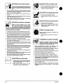 6
6
-
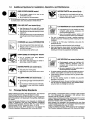 7
7
-
 8
8
-
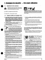 9
9
-
 10
10
-
 11
11
-
 12
12
-
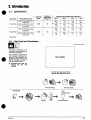 13
13
-
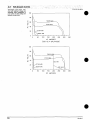 14
14
-
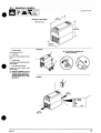 15
15
-
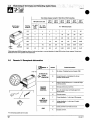 16
16
-
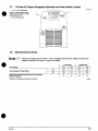 17
17
-
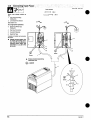 18
18
-
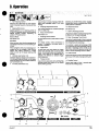 19
19
-
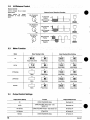 20
20
-
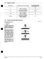 21
21
-
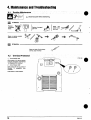 22
22
-
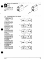 23
23
-
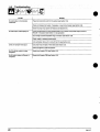 24
24
-
 25
25
-
 26
26
-
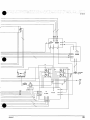 27
27
-
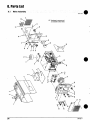 28
28
-
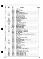 29
29
-
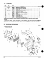 30
30
-
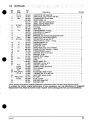 31
31
-
 32
32
-
 33
33
-
 34
34
-
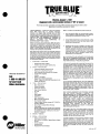 35
35
-
 36
36


Miller ADI 253 Le manuel du propriétaire
- Catégorie
- Système de soudage
- Taper
- Le manuel du propriétaire
- Ce manuel convient également à
dans d''autres langues
- English: Miller ADI 253 Owner's manual
Documents connexes
-
Miller LA088562 Le manuel du propriétaire
-
-
-
-
-
-
-
-
-
Miller XMT 304 CC AND CC/CV CE (460 V) Le manuel du propriétaire