GE ZBD0700KII Guide d'installation
- Catégorie
- Lave-vaisselle
- Taper
- Guide d'installation

If you have questions, call 800.626.2000 or visit our website at: www.monogram.com
Monogram.
®
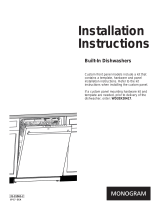
Installation
Instructions
Built-In Dishwashers
ZBD6800
ZBD6880
ZBD6890*
ZBD0700*
ZBD0710
Design Guide with
Installation Instructions
*For ZBD6890 and ZBD0700 also refer
to the instructions provided on the
template packed with that model.

Safety Information
2
CONTENTS
Installation Preparation
Parts Supplied..............................................................................3
Materials You Will Need ............................................................3
Tools You Will Need ....................................................................3
Models Available ........................................................................4
Advance Planning ......................................................................4
Prepare Dishwasher Enclosure ................................................4
Drain Requirements ....................................................................5
Prepare Electrical Wiring ..........................................................6
Prepare Hot Water Line..............................................................7
Installation Instructions
Step 1, Check Door Balance......................................................7
Step 2, Remove Wood Base, Install Leveling Legs ..............8
Step 3, Remove ToeKick ............................................................8
Step 4, Install Power Cord ........................................................8
Step 5, Install 90° Elbow ............................................................8
Step 6, Position Water Line and House Wiring......................9
Step 7, Install Drain Hose, Guide Through Cabinet ..............9
Step 8, Slide Dishwasher Partially Into Cabinet ....................9
Step 9, Install Trim Pieces..........................................................9
Step 10, Position Dishwasher Under Countertop ................10
Step 11, Level Dishwasher ......................................................11
Step 12, Secure Dishwasher To Cabinet ..............................12
Step 13, Connect Water Supply ..............................................13
Step 14, Connect Drain Line ....................................................13
Step 15, Connect Power Supply..............................................14
Step 16, Pre-Test Check List....................................................14
Step 17, Dishwasher Wet Test ................................................15
Step 18, Replace Toekick ........................................................15
Step 19, Literature ....................................................................15
Custom Panel Dimensions
Custom Panel for Models ZBD6890, ZBD0700......................15
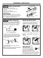
BEFORE YOU BEGIN
Read these instructions completely and carefully.
•
IMPORTANT — Save these instructions for
local inspector’s use. Observe all governing codes and
ordinances.
• Note to Installer — Be sure to leave these
instructions with the Consumer.
• Note to Consumer — Keep these instructions
with your Owner’s Manual for future reference.
• Skill Level — Installation of this dishwasher requires
basic mechanical and electrical skills. Proper installation
is the responsibility of the installer. Product failure due
to improper installation is not covered under the GE
Appliance Warranty.
• Completion Time — 1 to 3 Hours.
New installations require more time than replacement
installations.
•
IMPORTANT — The dishwasher MUST
be installed to allow for future removal from the
enclosure if service is required.
• If you received a damaged dishwasher, you should
immediately contact your dealer or builder.
READ CAREFULLY.
KEEP THESE INSTRUCTIONS.
FOR YOUR SAFETY
Read and observe all CAUTION and WARNINGS shown
throughout these instructions.
While performing installations described in this booklet,
gloves, safety glasses or goggles should be worn.
For Monogram local service in your area, 1.800.444.1845.
For Monogram service in Canada 1.888.880.3030
For Monogram Parts and Accessories, call 1.800.626.2002.

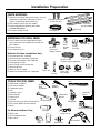
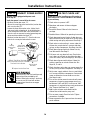
TOOLS YOU WILL NEED:
Phillips head screwdriver
5/16" and 1/4" nutdriver
6" Adjustable wrench
Level
Carpenters square
Measuring tape
Safety glasses
Flashlight
Bucket to catch water when flushing the line
15/16" socket (optional for skid removal)
Gloves
For New Installations Only:
Tubing cutter
Drill and appropriate bits
Hole saw set
MATERIALS YOU WILL NEED:
Ferrule, compression nut and 90° Elbow (3/8" NPT
external thread on one end, opposite end sized to fit
water supply)
Thread seal tape
UL Listed wire nuts (3)
Materials For New Installations Only:
Air gap for drain hose, if required
Waste tee for house plumbing, if applicable
Electrical cable or power cord, if applicable
Screw type hose clamps
Strain relief for electrical connection
Hand shut-off valve
Water line 3/8" min. copper
Coupler for extending drain line, if applicable
PARTS SUPPLIED:
Two #8-18 x 5/8" Phillips special head screws, to secure
dishwasher to underside of countertop or sides of
cabinets. (Taped to top side of dishwasher.)
Side and top trim pieces (on some models)
Template with mounting hardware (not shown)
for Model ZBD6890 Only
Drain Hose and Hose Clamp
Installation Preparation
3
Wire Nuts (3)
Hot Water line
Screw Type
Hose Clamps
Coupler
Hand
Shut-Off
Valve
#8 Phillips Special Head
Screws 5/8" Long
Hole Saw Set
Measuring Tape
Tubing Cutter
Drill and Bits
Phillips
Head
Screwdriver
15/16" Socket
1/4"
and 5/16"
Nutdriver
Safety Glasses
6" Adjustable
Wrench
Bucket
Flashlight
Gloves
Carpenters
Square
Level
Thread
Seal Tape
Air Gap
Strain Relief
Drain Hose
Hose Clamp
90° Elbow,
Ferrule and
Compression Nut
Electrical Cable
(or Power Cord, if applicable)
Waste Tee
Trim Pieces
(on some models)

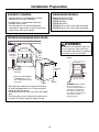
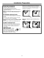
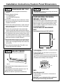
PREPARE DISHWASHER ENCLOSURE
• The rough cabinet opening must be at least 24" deep,
24" wide and approximately 34-1/2" high from floor to
underside of the countertop.
• Plumbing and electrical service must enter the shaded
area.
• The dishwasher must be installed so that drain hose is
no more than 10 feet in length for proper drainage.
WARNING
To reduce the risk of electric shock, fire,
or injury to persons, the installer must
ensure that the dishwasher is completely
enclosed at the time of installation.
Clearance for Door
Opening 2" Minimum
Countertop
Dishwasher
28-3/8"
Cabinets
Square
and
Plumb
Floor MUST
be Even with
Room Floor
This Wall Area
must be Free of
Pipes or wires
34-1/2" Min.
Underside of
Countertop
to Floor
24"
Min.
24" Min.
5" 5"
4"
4"
6"
24"
*24"
34"
Adjustable
to 35"
Figure B
Installation Preparation
CLEARANCES: When installed
into a corner, allow 2" min.
clearance between dishwasher
and adjacent cabinet, wall or
other appliances. Allow 28-3/8"
min. clearance from the front of
the dishwasher for door
opening (Figure B).
4
DISHWASHER MODELS
ZBD0710 SS, Stainless Steel
ZBD6880 SS, Stainless Steel
ZBD6800 BB, Black
ZBD6800 WW, White
ZBD6890 Requires a 3/4" custom panel and handle
ZBD0700 Requires a 3/4" custom panel and handle
ADVANCE PLANNING
• These dishwashers are designed for versatility,
adaptable to virtually any installation.
• All models have a full length door without the
traditional access panel.
• These dishwashers may be installed beneath
countertops of stone or other materials that will not
accept screws. No trim kit required.
*Dishwasher models ZBD6890
and ZBD0700 require a 3/4”
thick custom panel and will be
24-3/4” deep.
Figure A

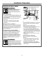
DRAIN REQUIREMENTS
• Follow local codes and ordinances.
• Do not exceed 10 feet distance to drain.
• Do not connect drain lines from other devices to the
dishwasher drain hose.
NOTE: An air gap must be used, if waste tee or disposer
connection is less than 18" above floor to prevent
siphoning.
DETERMINE DRAIN METHOD
The type of drain installation depends on the following
question.
Do local codes or ordinances require an air gap?
Is waste tee less than 18" above floor?
If the answer to either question is YES, Method 1 MUST
be used.
• If the answers are NO, either method may be used.
CABINET PREPARATION
• Drill a 1-1/2" dia. hole in the cabinet wall within the
shaded areas shown in Figure A for the drain hose
connection. The hole should be smooth with no
sharp edges.
Method 1—Air Gap with Waste Tee or Disposer
An air gap must be used when required by local codes and
ordinances. The air gap must be installed according to
manufacturers instructions.
Method 2—“High Drain Loop” with Waste Tee or
Disposer
Figure C
Figure D
32"
Min.
18"
Min.
32"
Min.
18"
Min.
IMPORTANT — When
connecting drain line to disposer,
check to be sure that drain plug has
been removed. DISHWASHER WILL
NOT DRAIN IF PLUG IS LEFT IN PLACE.
Remove
Hopper
Plug
5
Installation Preparation

6
Installation Preparation
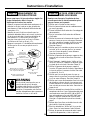
PREPARE ELECTRICAL WIRING
WARNING
FOR PERSONAL SAFETY: Remove house
fuse or open circuit breaker before
beginning installation. Do not use an
extension cord or adapter plug with this
appliance.
Electrical Requirements
• This appliance must be supplied with 120V, 60 Hz., and
connected to an individual properly grounded branch
circuit, protected by a 15 or 20 ampere circuit breaker
or time delay fuse.
• Wiring must be 2-wire with ground and rated for
75°C (176°F).
• If the electrical supply does not meet the above
requirements, call a licensed electrician before
proceeding.
Grounding Instructions—Cable Direct
This appliance must be connected to a grounded metal,
permanent wiring system, or an equipment grounding
conductor must be run with the circuit conductors and
be connected to the equipment grounding terminal or
lead on the appliance.
Grounding Instructions—Power Cord Models
This appliance must be grounded. In the event of a
malfunction or breakdown, grounding will reduce the
risk of electric shock by providing a path of least
resistance for electric current. This appliance is
equipped with a cord having an equipment grounding
conductor and a grounding plug. The plug must be
plugged into an appropriate outlet that is installed and
grounded in accordance with all local codes and
ordinances.
WARNING
The improper connection of the equipment
grounding conductor can result in a risk
of electric shock. Check with a qualified
electrician or service representative if you
are in doubt that the appliance is properly
grounded.
For models equipped with power cord: Do not modify
the plug provided with the appliance; if it will not fit the
outlet, have a proper outlet installed by a qualified
technician.
Cabinet Preparation and Wire Routing
• The wiring may enter the opening from either side,
rear or the floor within the shaded area.
• Cut a 1-1/2" max. dia. hole to admit the electrical
cable. Cable direct connections may pass through
the same hole as the drain hose and hot water line,
if convenient. If cabinet wall is metal, the hole edge
must be covered with a bushing.
• NOTE: Power cords with plug must pass through a
separate hole.
Electrical Connection to Dishwasher
Electrical connection is on the right front of
dishwasher.
• For cable direct connections the cable must be
routed as shown in Figure E. Cable must extend
a minimum of 24" from the rear wall.
• For power cord connections, install a 3-prong
grounding type receptacle in the sink cabinet rear
wall, 6" min. or 18" max. from the opening, 6" to 18"
above the floor.
White
18"
6"
24"
from Wall
3"
from
Cabinet
Alternate
Receptacle
Location
Ground
Black
1-1/2" Dia.
Hole (Max.)
18"
6"
Receptacle
Location
Area
Figure E

PREPARE HOT WATER LINE
• The line may enter from either side, rear or floor
within the shaded area shown in Figure F.
• The line may pass through the same hole as the
electrical cable and drain hose. Or, cut an additional
1-1/2" dia. hole to accommodate the water line.
If power cord with plug is used, water line must
not pass through power cord hole.
Water Line Connection
• Turn off the water supply.
• Install a hand shut-off valve in an accessible location,
such as under the sink. (Optional, but strongly
recommended and may be required by local codes.)
• Water connection is on the left side of the dishwasher.
Install the hot water inlet line, using no less than 3/8"
O.D. copper tubing. Route the line as shown in Figure F
and extend forward at least 19" from rear wall.
• Adjust water heater for 120°F to 150°F temperature.
• Flush water line to clean out debris.
• The hot water supply line pressure must be 20-120 PSI.
Installation Instructions
7
Cabinet Face
Shut-off
Valve
2" From Floor
19" From Wall
2"
From
Cabinet
1-1/2" Dia.
Hole
Hot
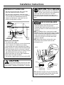
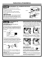
CAUTION
Do not remove wood base until you are ready
to install the dishwasher. The dishwasher will tip over
when the door is opened if the wood base is removed.
BEFORE YOU BEGIN
Locate and set aside (for use in Step 12) the
2 Phillips special head screws wrapped with
yellow tape and stuck to the top or side of the
dishwasher. Remove drain hose from upper rack, if
it has not been pre-installed, and set aside for use in
Step 7.
Figure F
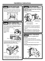
CHECK DOOR BALANCE
• With dishwasher on the wood skid, check the door
balance by opening and closing the door.
• If the door drops when released, increase the spring
tension. If the door rises when released, decrease
the tension.
NOTE: The addition of the custom panel on model
ZBD6890 will require exchange of the factory installed
springs. Use the heavy-duty springs provided. See the
custom panel template for additional instructions.
• Position the spring for increased or decreased
tension as required.
NOTE: Adjust both balance springs to the same
amount of tension to prevent excessive door
twisting during use.
TIP: If door does not open easily or falls too quickly,
check the spring cable routing. Check that the cable
is properly aligned on the pulley (as shown).
STEP 1
Correct Spring
Cable Routing
Increase
Tension
Decrease
Tension
Pulley
Shoulder
Use This
Mounting
Hole
Figure G

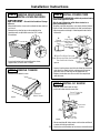
REMOVE WOOD BASE,
INSTALL LEVELING LEGS
IMPORTANT — Do not kick off wood base! Damage
will occur.
• Move the dishwasher close to the installation location and lay it
on its back.
• Remove the four leveling legs on the underside of the
wood base with an adjustable wrench or 15/16" socket.
• Discard base.
• Screw leveling legs back into the dishwasher frame,
approximately 1/4" from frame as shown.
STEP 2
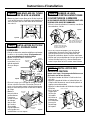
REMOVE TOEKICK
• Remove the two toekick screws.
STEP 3
8
T
oekick
Remove 2
Toekick Screws
Installation Instructions
Figure H
Approx.
1/4"
Figure J
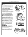
INSTALL POWER CORD
Use Power Cord Kit WX09X70910 available for purchase from an
authorized GE Appliances dealer.
Skip this step if dishwasher will be direct wired or has a
factory installed power cord.
The power cord and connections must comply with the National
Electrical Code, Section 422 and/or local codes and ordinances.
• Maximum power cord length is 4 feet beyond the back of the
dishwasher.
• Connect incoming power cord white (or ribbed) to dishwasher
white, black (or smooth) to black and ground to dishwasher
green wire. Use UL listed wire nuts of appropriate size.
• Replace junction box cover. Be sure wires are not pinched
under the cover.
STEP 4
White
Ground
Black
Check That White, Black and
Green Dishwasher Wires Are Threaded
Thru Small Hole in Bracket
Remove
Junction Box
Cover
Insert Power
Cord Wires Thru
Strain Relief
and Tighten
Use UL Listed
Wire Nuts
A
C
B
D
Figure K
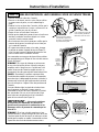
INSTALL 90° ELBOW
• Wrap 90° elbow with thread seal tape.
• Install a 90° elbow onto the water valve.
• Do not overtighten 90° elbow, water valve bracket could bend
or water valve fitting could break.
• Position the end of the elbow to face the rear of the dishwasher
.
STEP 5
Front of Dishwasher
90°
Elbow
Thread
Seal Tape
Fill
Hose
Water Valve
Bracket
Figure L

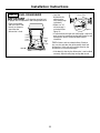
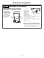
INSTALL DRAIN HOSE,
GUIDE THROUGH CABINET
• Remove tape and wire tie holding the clamp to the
drain hose. Be careful not to damage the drain hose.
• Stand the dishwasher upright.
• Slip the supplied
hose clamp over
the large end of
the hose. Do not
tighten.
• Push hose over the drain outlet on the back side of
the dishwasher. See illustration. Push the hose over
the outlet and against the shoulder stop.
• Tighten the hose clamp with a 1/4" nut driver.
• Position the dishwasher in front of the opening.
Insert drain hose into the cabinet side. If power cord
is used, guide the end through a separate hole.
STEP 7
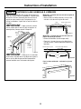
INSTALL TRIM PIECES
Skip this step if trim is not supplied with the
dishwasher.
• Locate trim strips inside dishwasher.
• Press trim onto the tub flange on each side. Start
with the top edge, pressing on as you move towards
the bottom.
• Press the two top trim pieces on each side of
the latch.
• Open and close the door to check that trim does not
bind and does not interfere with door latch.
STEP 9
POSITION WATER LINE
AND HOUSING WIRING
• Position water supply line and house wiring on the
floor of the opening to avoid interference with base
of dishwasher and components under dishwasher.
STEP 6
9
Figure Q
Trim Strip
Trim
Strip
Trim
Strip
Water
Line
House
Wiring
5"
5"
4"
6"
4"
Installation Instructions
Figure M
SLIDE DISHWASHER
PARTIALLY INTO CABINET
DO NOT PUSH AGAINST FRONT PANEL WITH KNEES.
DAMAGE WILL OCCUR.
• Slide dishwasher into the opening a few inches
at a time.
• As you proceed, pull the drain hose through the
opening under the sink. Stop pushing when the
dishwasher is a few inches forward of adjacent
cabinetry.
• Make sure drain hose is not kinked under the
dishwasher and there is no interference with the
water line and wiring or any other component.
STEP 8
Do Not Push Against
Front Door Panel With
Knee. Damage to The
Door Panel Will Occur.
Reposition Dishwasher
by Grasping Both
Sides With Hands
Figure P
Power Cord
(If Used)
Water
Line
House
Wiring
Drain
Hose
Insulation
Blanket
Figure O
Figure N
Drain
Outlet
Hose
Clamp
Shoulder
Stop
Flapper
Valve—Do
Not Remove

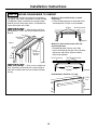
POSITION DISHWASHER UNDER COUNTERTOP
STEP 10
10
• Push the dishwasher into the cabinet.
• Push at the sides with your hands. Do not use your
knee against the door since door damage will occur.
• Check that the tub insulation blanket does not get
“bunched-up” or interfere with the springs as you
slide it into the cabinet.
• Center the dishwasher in the opening.
• Check that the edges of the dishwasher door are
behind the cabinet frame and aligned with the front
face of the cabinet as shown.
• Carefully open and close the door to ensure that the
door panel does not catch or rub on the cabinet frame.
• If the door catches or rubs on the frame, reposition
and/or level the unit (see Step 11) until the door moves
freely and does not contact the cabinet frame.
The controls are designed to be hidden by your
countertop. Align the dishwasher as shown in Figure T.
NOTE: If the drain hose gets trapped between the wall
and the back side of the dishwasher, it can prevent the
dishwasher from sliding all the way back into the
cabinet opening, and thus preventing a flush fit with
the kitchen cabinet panels.
TIP: For best appearance installations of custom panel
models, it may be necessary to cut off the back panel
of the tub insulation blanket so that the dishwasher
door panel can be aligned flush with the kitchen
cabinet panels.
The leveling legs can be used to increase or decrease
the amount of gap between the controls and the
countertop affecting the visibility of the controls.
Leave a 1/2" minimum gap between the underside
of the countertop and the top of the dishwasher
door (see Figure V).
IMPORTANT — Leave a 1/2" minimum
gap between the controls and the underside of the
countertop to prevent condensation and damage to the
control panel from screwheads.
NOTE: If this dishwasher is replacing an existing
dishwasher, the old countertop bracket screw holes
may not be in the correct position to accept a top
control model. New holes may be required.
Control Panel
Countertop
Minimum 1/2" Gap
for Clearance
Countertop
1/2" min.
Figure U
Figure V
Top View
Controls Hidden
by Countertop
Installation Instructions
Door
Fits and
Swings
Back
Behind
Cabinet
Frame
Correct
Alignment
Door Catches
on Cabinet Frame
Incorrect
Alignment
Figure S
Figure T
Do Not Push Against
Front Door Panel With
Knee. Damage to The
Door Panel Will Occur.
Reposition Dishwasher
by Grasping Both
Sides With Hands
Figure R

LEVEL DISHWASHER
IMPORTANT — Dishwasher must be level
for proper dish rack operation and wash performance.
• Place level on door
and rack track inside
the tub as shown to
check that the
dishwasher is level.
• Level the
dishwasher by
adjusting the
four leveling legs
individually.
• Make sure 1/2"
minimum gap is
maintained (see
Figure V).
• If adjustment to the right rear leveling leg is required,
gain access by loosening junction box bracket screw
(through the access hole) and rotate bracket
clockwise.
TIP: Pull lower rack out, about halfway. Check to
be sure the rack does not roll forward or back into
dishwasher. If the rack rolls in either direction, the
dishwasher must be leveled again.
• If the door hits the tub, the dishwasher is not installed
correctly. Adjust leveling legs to align door to tub.
STEP 11
11
Check
Level
Side
To Side
Check
Level
Front
to Back
Turn Legs
to Adjust
Access Hole
Installation Instructions
Figure W
Figure X

12
Installation Instructions
SECURE DISHWASHER TO CABINET
STEP 12
The dishwasher must be secured to the countertop or
the cabinet sides. When countertops are made of wood,
use Method 1. When countertops are granite or other
materials that will not accept screws, use Method 2 to
secure dishwasher at the sides.
IMPORTANT — After leveling, verify that
the dishwasher is still in the correct position shown in
Step 10.
IMPORTANT — Drive screws straight and
flush. Protruding screw heads will scratch the top or
sides of the control panel and can interfere with door
closing.
Method 1—Secure dishwasher to wood
countertop
• Fasten the dishwasher to the underside of the
countertop with 2 Phillips screws provided.
Method 2—Secure dishwasher with side
mounting brackets
• Remove plug buttons (one on each side).
• Install screw through the hole in the side of the
dishwasher and into the adjacent cabinet.
Reinstall plug buttons.
Both Methods—Maintain 1/2" Gap
Countertop
Mounting
Brackets
Tub
Frame
Side Mounting
Brackets
Figure Y
Figure AA
Brackets
Wood Countertop
Screws
Plug Buttons
Side Mounting Brackets
Stone Countertop
Figure Z
Figure Y
1/2” Min.
Gap
Figure BB

13
Installation Instructions
CONNECT DRAIN LINE
FOLLOW ALL LOCAL CODES AND ORDINANCES.
The drain hose molded end will fit 5/8" or 1" diameter
connections on the air gap, waste tee or disposer. Cut
on the marked line as required for your installation.
• If a longer drain hose is required, add up to 42" of
length for a total of 10 ft. to the factory installed hose.
Use 5/8" or 7/8" inside diameter hose and a coupler to
connect the two hose ends. Secure the connection
with hose clamps.
• Secure the drain hose to the air gap, waste tee or
disposer with clamps.
NOTE: TOTAL DRAIN HOSE LENGTH MUST NOT EXCEED
10 FEET FOR PROPER DRAIN OPERATION.
DRAIN LINE INSTALLATION
• Connect drain line to air gap, waste tee or disposer
using either previously determined method.
Method 1—Air gap with waste tee or disposer
Method 2—“High drain loop” with waste tee or
disposer
IMPORTANT — When
connecting drain line to disposer,
check to be sure that drain plug has
been removed. DISHWASHER WILL
NOT DRAIN IF PLUG IS LEFT IN PLACE.
TIP: Avoid unnecessary service call charges. Always
be sure disposer drain plug has been removed before
attaching dishwasher drain hose to the disposer.
STEP 14
CONNECT WATER SUPPLY
Connect water supply line to 90° elbow.
• Slide compression nut, then ferrule over end of
water line.
• Insert water line into 90° elbow.
• Slide ferrule against elbow and secure with
compression nut.
IMPORTANT — Check to be sure that door
spring does not rub or contact the fill hose or water supply
line. Test by opening and closing the door. Re-route the
lines if a rubbing noise or interference occurs.
STEP 13
90° Elbow
Ferrule
90° Elbow
Compression Nut
Door Spring
Hot Water
Supply Line
Figure CC
Cutting Line
1"
5/8"
IMPORTANT: Do not cut corrugated
portion of hose
Figure DD
Hose Clamp
Coupler
Hose Clamp
Figure EE
Figure FF
Waste Tee Installation Disposer Installation
Figure GG
Fasten to underside
of countertop
32"
Min.
18"
Min.
Fasten to underside
of countertop
32"
Min.
18"
Min.
Disposer InstallationWaste Tee Installation
Remove
Hopper
Plug

14
Installation Instructions
PRE-TEST CHECK LIST
Review this list after installing your dishwasher to
avoid charges for a service call that is not covered
by your warranty.
Check to be sure power is OFF.
Open door and remove all foam and paper
packaging.
Locate the Owner’s Manual in the literature
package.
Read the Owner’s Manual for operating instructions.
Check door opening and closing. If door does not
open and close freely or tends to fall, check spring
cable routing and spring adjustments. See Step 1.
Check to be sure that wiring is secure under the
dishwasher, not pinched or in contact with door
springs or other components. See Steps 8 and 10.
Check door alignment with tub. If door hits tub,
level dishwasher. See Step 11.
Pull lower rack out, about half way. Check to be
sure it does not roll back or forward on the door.
If the rack moves, adjust leveling legs. See Step 11.
Check door alignment with cabinet. If door hits
cabinet, reposition or relevel dishwasher. See
Steps 10, 11 and 12.
Check that door spring does not contact water line,
fill hose, wiring or other components. See Step 13.
Verify water supply and drain lines are not kinked
or in contact with other components. Contact with
motor or dishwasher frame could cause noise.
See Steps 6 and 8.
Turn on the sink hot water faucet and verify water
temperature. Incoming water temperature must
be between 120°F and 150°F. A minimum of 120°F
temperature is required for best wash performance.
See “Prepare Hot Water Line,” page 7.
Add 2 quarts of water to the bottom of the
dishwasher to lubricate the pump seal.
Turn on water supply. Check for leaks. Tighten
connections if needed.
Remove protective film if present from the control
panel and door.
STEP 16
CONNECT POWER SUPPLY
Skip this step if equipped with power cord.
Go to step 16.
Verify that power is turned off at the source.
• Remove junction box cover “A”.
• Secure house wiring to the back of the junction box
with a strain relief “B”.
• Locate the three dishwasher wires, (white, black
and green) with stripped ends. Insert dishwasher
wires through the small hole in the junction box “C”.
Use wire nuts to connect incoming ground to green,
white to white and black to black “D”.
• Replace junction box cover “E”. Check to be sure
that wires are not pinched under the cover.
WARNING
If house wiring is not 2-wire with ground,
a ground must be provided by the
installer. When house wiring is aluminum,
be sure to use UL Listed anti-oxidant
compound and aluminum-to-copper
connectors.
STEP 15
White
Ground
Black
Check That White, Black and
Green Dishwasher Wires Are Threaded
Thru Small Hole in Bracket
Remove
Junction Box
Cover
Insert Power
Cord Wires Thru
Strain Relief
and Tighten
Use UL Listed
Wire Nuts
Replace Junction Box Cover
A
C
E
B
D
Figure HH

15
REPLACE TOEKICK
• Place toekick against the legs of the dishwasher.
• Align the toekick with the bottom edge and make sure it is
against the floor.
• Insert and tighten the two toekick attachment screws. The
toekick should stay in contact with the floor.
TIP: Make sure toekick is against floor to minimize noise.
STEP 18
T
o
e
k
ic
k
Attachment Screws
Installation Instructions/Custom Panel Dimensions
LITERATURE
• Be sure to leave complete literature package and installation
instructions with the consumer.
STEP 19
Figure II
DISHWASHER WET TEST
Turn on power supply (or plug power cord into outlet, if
equipped).
Start the unit to check for leaks.
– Push RINSE ONLY pad.
– Push START/RESET pad one time.
– Close door.
Check to be sure that water enters the dishwasher. If water
does not enter the dishwasher, check to be sure that water
and power are turned on.
Check for leaks under the dishwasher. If a leak is found, turn
power supply off, then tighten connections. Restore power
after leak is corrected.
Check for leaks around the door. A leak around the door
could be caused by door rubbing or hitting against adjacent
cabinetry. Reposition the dishwasher if necessary. See Step 12.
The dishwasher will drain and turn off about 5 minutes after it
was started. Check drain lines. If leaks are found, turn power
off at the breaker and correct plumbing as necessary. Restore
power after corrections are made. See Step 15.
Open dishwasher door and make sure most of the water has
drained. If not, check that disposer plug has been removed
and/or air gap is not plugged. See Step 14. Also check drain
line for kinking.
Run the dishwasher through another “Rinse Only” cycle.
Check for leaks and correct if required.
STEP 17
CUSTOM PANEL FOR MODEL
ZBD6890, ZBD0700
These dishwashers require a field installed 3/4" thick custom
panel and custom handle. An installation template is packed
with these models and may be obtained in advance. Order
Pub. No. 31-30569-1. Complete panel installation instructions
are included on the template.
CUSTOM PANEL SIZE REQUIREMENTS
HEIGHT
Panel height must be between 30-1/16" and 30-1/4".
• If the panel height is more than 30-1/4" it will prevent the door
from swinging open.
• If the panel height is less than 30-1/16" it will not cover the
dishwasher door frame.
• The top of the custom panel must be flush with the top of the
door. The 1/2" minimum gap between the top of the door and
the bottom of the countertop must be maintained.
WIDTH
Panel width must be 23-3/4".
• If the panel width is less than 23-3/4" it will not cover the
dishwasher frame.
IMPORTANT: To ensure optimum door balance performance,
the custom panel must not weigh more than 14 lbs
.
Minimum 1/2" Gap
for Clearance
Countertop
1/2" min.
23-3/4"
30-1/16" Min.
30-1/4" Max.

Pub. No. 31-30586
Part No. 206C1559P126
11-04 JR
NOTE: While performing installations described in this book,
safety glasses or goggles should be worn.
For Monogram
®
local service in your area, call
1.800.444.1845.
NOTE: Product improvement is a continuing endeavor at
General Electric. Therefore, materials, appearance and
specifications are subject to change without notice.

En cas de question, appeler 800.626.2000 ou rendre visite à notre site web : www.monogram.com
Monogram.
®
Instructions
d’installation
Lave-vaisselle encastré
ZBD6800
ZBD6880
ZBD6890*
ZBD0700*
ZBD0710
Guide de conception
Instructions d’installation
*Pour ZBD6890 et ZBD0700, consulter
aussi les instructions imprimées sur
le gabarit fourni avec ce modèle.

Information de sécurité
2
CONTENU
Préparation pour l’installation
Pièces fournies ............................................................................3
Matériaux nécessaires ..............................................................3
Outils nécessaires ......................................................................3
Modèles disponibles ..................................................................4
Planification préalable................................................................4
Préparation de l’enceinte du lave-vaisselle ..........................4
Égout..............................................................................................5
Préparation pour le branchement électrique ........................6
Préparation du tuyau d’eau chaude ........................................7
Instructions d’installation
Étape 1, Vérifier l’équilibre de la porte....................................7
Étape 2, Dépose de la base en bois, installation
des pattes de mise à niveau ......................................8
Étape 3, Dépose de la plinthe....................................................8
Étape 4, Installation du cordon d’alimentation ......................8
Étape 5, Installation du coude à angle droit ..........................8
Étape 6, Mise en place du tuyau d’eau et
des fils de la maison....................................................9
Étape 7, Installation du tuyau de vidange,
guidage dans l’armoire ..............................................9
Étape 8, Glisser le lave-vaisselle partiellement dans
l’ouverture de l’armoire ..............................................9
Étape 9, Installation des pièces de finition ............................9
Étape 10, Mise en position du lave-vaisselle
sous le plan de travail ............................................10
Étape 11, Mise à niveau du lave-vaisselle............................11
Étape 12, Fixation du lave-vaisselle à l’armoire ..................12
Étape 13, Branchement de l’alimentation d’eau ..................13
Étape 14, Branchement du tuyau de vidange ......................13
Étape 15, Branchement de l’alimentation électrique..........14
Étape 16, Liste de vérification avant de faire les essais ....14
Étape 17, Essai du lave-vaisselle avec de l’eau ..................15
Étape 18, Repose de la plinthe................................................15
Étape 19, Documentation ........................................................15
Dimensions du panneau sur commande
Panneau sur commande pour modèles
ZBD6890, ZBD0700 ....................................................................15
AVANT DE COMMENCER
Il faut lire soigneusement toutes ces instructions.
•
IMPORTANT — Conserver ces instructions
afin que l’inspecteur local s’en serve. Il faut respecter tous
les codes et règlements.
•
Remarque pour l’installateur
— Ne pas oublier
de remettre ces instructions au consommateur.
•
Remarque pour le consommateur
—
Il faut garder ces instructions avec le manuel d’utilisation,
pour consultation ultérieure.
•
Niveau de compétence
— L’installation de ce
lave-vaisselle demande des talents mécaniques et
électriques de base. L’installateur est responsable de
l’installation appropriée. La garantie des appareils
ménagers de GE ne couvre pas les défaillances du
produit causées par une mauvaise installation.
•
Durée d’installation — 1 à 3 heures.
Les installations initiales demandent plus de temps que
les installations de remplacement.
•
IMPORTANT — Le lave-vaisselle DOIT être
installé de manière à permettre la dépose ultérieure de
l’enceinte afin de permettre toute intervention.
• Si le lave-vaisselle livré est endommagé, il faut contacter
immédiatement le concessionnaire ou l’entrepreneur de
construction.
LIRE ATTENTIVEMENT.
IL FAUT GARDER CES
INSTRUCTIONS.
SÉCURITÉ
Il faut lire et observer tous les avertissements (PRUDENCE
et ATTENTION) montrés dans ces instructions.
Pendant l’installation décrite dans ce livret, il faut porter
des gants et des lunettes de sécurité.
Pour le service local Monogram dans votre région :
1.800.444.1845.
Pour le service Monogram au Canada : 1.888.880.3030
Pièces et accessoires Monogram, appeler le :
1.800.626.2002.

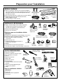
OUTILS NÉCESSAIRES :
Tournevis cruciforme
Tournevis à douille de 5/16 po et 1/4 po
Clé à molette de 15 cm (6 po)
Niveau
Equerre de menuisier
Mètre ruban
Lunettes de sécurité
Lampe de poche
Seau pour attraper l’eau lors de la purge
du tuyau
Douille de 15/16 po (optionnelle pour
la dépose de la palette)
Gants
Pour les installations initiales
seulement :
Coupe-tube
Perceuse et mèches appropriées
Scie-cloche
MATÉRIAUX NÉCESSAIRES :
Bague, écrou de compression et coude à angle droit
(filetage externe de 3/8 po à une extrémité, l’autre
extrémité correspondant à l’alimentation d’eau)
Ruban d’étanchéité de filetage
Serre-fils sur la liste UL (3)
Matériaux pour une installation initiale
seulement :
Dispositif anti-siphon pour le tuyau de vidange, si nécessaire
Raccord en té pour la plomberie d’égout, si nécessaire
Câble électrique ou cordon d’alimentation,
si nécessaire
Colliers de tuyau à vis
Dispositif de réduction de tension pour les
branchements électriques
Robinet
Conduite d’eau en cuivre de 3/8 po minimum
Manchon pour allonger le tuyau de vidange, si nécessaire
PIÈCES FOURNIES :
Deux vis cruciformes spéciales #8-18 x 5/8 po (enveloppées
dans du ruban adhésif sur le côté supérieur du lave-vaisselle)
pour fixer le lave-vaisselle au dessous du plan de travail ou
aux côtés des armoires
Pièces de finition latérales et supérieure (sur certains modèles)
Gabarit avec quincaillerie de montage (non illustré)
Modèle ZBD6890 seulement
Tuyau de vidange et collier de tuyau
Préparation pour l’installation
3
Serre-fils (3)
Tuyau d’eau
chaude
Colliers de
tuyau à vis
Manchon
Robinet
Vis cruciformes
spéciales #8 de 5/8
po de long
Scie-cloche
Mètre ruban
Coupe-tube
Perceuse et
mèches
appropriées
Tournevis
cruciforme
Douille de
15/16 po
Tournevis à douille
de 5/16 po et 1/4 po
Lunettes de sécurité
Clé à molette
de 15 cm (6 po)
Seau
Lampe de poche
Gants
Equerre de
menuisier
Niveau
Ruban
d’étanchéité
de filetage
Dispositif
anti-siphon
Dispositif de
réduction de
tension
Tuyau de vidange
Collier
de tuyau
Coude à angle droit,
bague et écrou de
compression
Câble électrique (ou cordon
d’alimentation, si nécessaire)
Raccord en té
Pièces de finition
(sur certains
modèles)

Espace pour l’ouverture
de la porte, au mois 5 cm (2 po)
Plan de travail
Lave-vaisselle
72 cm
86,4 cm (34 po)
ajustable à
88,9 cm (35 po)
10 cm
15 cm
10 cm
Armoire
à l’équerre
et d’aplomb
Le sol DOIT
être au même
niveau que le sol
de la pièce
Cette portion du mur
ne doit pas avoir
de tuyaux ni de fils
88 cm
(34-1/2 po) Min.
dessous du plan
de travail au sol
61 cm
(24 po)
Min.
61 cm
(24 po) Min.
12,5
cm
12,5
cm
*61 cm
(24 po)
61 cm
(24 po)
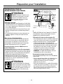
Figure B
Préparation pour l’installation
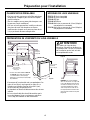
ESPACES : En cas d’installation
dans un coin, laisser un espace de
5 cm (2 po) minimum entre le lave-
vaisselle et l’armoire, le mur ou un
autre appareil adjacent. Il doit y
avoir un espace d’au mois 72 cm
(28-3/8 po) devant le lavevaisselle
pour permettre l’ouverture la porte
(Figure B).
4
MODÈLES DE LAVE-VAISSELLE
ZBD0710 SS, Acier inoxydable
ZBD6880 SS, Acier inoxydable
ZBD6800 BB, Noir
ZBD6800 WW, Blanc
ZBD6890 Nécessite un panneau de 1,9 cm (3/4 po) et
une poignée sur commande
ZBD0700 Nécessite un panneau de 1,9 cm (3/4 po) et
une poignée sur commande
PLANIFICATION PRÉALABLE
• Ces lave-vaisselle sont conçus afin d’être polyvalents
et de pouvoir s’adapter à pour ainsi dire n’importe
quelle installation.
• Tous les modèles ont une porte pleine longueur sans
le panneau d’accès traditionnel.
• Ces lave-vaisselle peuvent être installés au-dessous
des plans de travail faits de pierre ou d’autres
matériaux dans lesquels on ne peut pas placer de vis.
Il n’y a pas besoin de trousse de garniture.
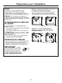
*Les lave-vaisselles modèles ZBD6890
et ZBD0700 nécessitent un panneau
sur commande de 1,9 cm (3/4 po)
d’épaisseur et aura 62,9 cm (24-3/4 po)
de profondeur.
Figure A
ATTENTION
Pour réduire le risque de choc
électrique, d’incendie ou de blessures,
l’installateur doit s’assurer, au moment
de l’installation, que le lave-vaisselle
est complètement enclos.
• L’ouverture de l’armoire doit avoir une profondeur d’au
moins 61 cm (24 po), une largeur d’au moins 61 cm
(24 po) et une hauteur d’environ 88 cm (34-1/2 po),
du sol au-dessous du plan de travail.
• La plomberie et l’électricité doivent entrer dans la zone
ombrée.
• Le lave-vaisselle doit être installé de manière que le
tuyau de vidange n’ait pas une longueur supérieure
à 3 m (10 pi) afin d’obtenir un bon écoulement.
PRÉPARATION DE L’ENCEINTE DU LAVE-VAISSELLE
La page est en cours de chargement...
La page est en cours de chargement...
La page est en cours de chargement...
La page est en cours de chargement...
La page est en cours de chargement...
La page est en cours de chargement...
La page est en cours de chargement...
La page est en cours de chargement...
La page est en cours de chargement...
La page est en cours de chargement...
La page est en cours de chargement...
La page est en cours de chargement...
-
 1
1
-
 2
2
-
 3
3
-
 4
4
-
 5
5
-
 6
6
-
 7
7
-
 8
8
-
 9
9
-
 10
10
-
 11
11
-
 12
12
-
 13
13
-
 14
14
-
 15
15
-
 16
16
-
 17
17
-
 18
18
-
 19
19
-
 20
20
-
 21
21
-
 22
22
-
 23
23
-
 24
24
-
 25
25
-
 26
26
-
 27
27
-
 28
28
-
 29
29
-
 30
30
-
 31
31
-
 32
32


GE ZBD0700KII Guide d'installation
- Catégorie
- Lave-vaisselle
- Taper
- Guide d'installation
dans d''autres langues
- English: GE ZBD0700KII Installation guide
Documents connexes
Autres documents
-
Bertazzoni DW24XT Installation Instructions Manual
-
GE Profile PDW1800KWW Guide d'installation
-
Yes ZDT985SSNSS Guide d'installation
-
 GE Monogram ZDT975SPJSS DL baa64a09c955faa48ffb35ce0d93
-
 GE Monogram ZDT975SPJSS Guide d'installation
-
Whirlpool 285320 Mode d'emploi
-
Monogram ZDT985SINII Manuel utilisateur
-
Pylex 10555 Guide d'installation

