SCS Sentinel AAM0086 Le manuel du propriétaire
- Taper
- Le manuel du propriétaire

TRANSPONDEURCLAVIER SANS FIL
SENTINEL
FR
SÉLECTEUR À CLÉ
INFO
le sélecteur à clé
est sans polarité.
IMPORTANT :
Référez-vous au
numéro de la carte
électronique indiqué
sur la couverture de
votre notice
«Kit motorisation».
DL1
RV1
1 2 3 4 5 6 7 8 9 10 11 12 13 14 15 16 FS1FS2 FS3
P2
TIME
P3
PAUSE
P1
CODES
PD1
C1
24Vac
CTR51-01
CTR51 sélecteur à clé
C NO NC
NO C
DL1
RV1
1 2 3 4 5 6 7 8 9 10 11 12 13 14 FS1FS2 FS4
12V
24V
FS3
P2
TIME
P3
PAUSE
P1
CODES
F1
RL5 RL1 RL2 RL3
R6R5
R13
RL4
PD1
C1
+BATT-
CTR52-01
JP1
CTR52 sélecteur à clé
C NO NC
NO C
P2 P3P1
DL1
RV1
JP1
JP2
FS1FS2
24V
12V
BATT
FS4 FS3
CTR 57
- BATT+
12V
24V
JP1
CTR57 sélecteur à clé
C NO NC
NO C
P2 P3P1
DL1
RV1
JP1
FS1FS2
- BATT+
24V
12V
BATT
FS4 FS3
CTR 58
JP2JP3 12V
24V
JP1
CTR58 sélecteur à clé
C NO NC
NO C
1 2 3 4 5 6 7 8 9 10 20 21 22 23 24 25 26191817161514131211
F1
J2 J3J1
1 2 3
DL3
DL4
DL5
DL6
DL7
DL8
DL9
DL10
DL11
RV1
JP2
1 2 3
JP1
CTR50 sélecteur à clé
C NO NC
NO C
INSTALLATION :
1 - Passer les fils dans
trou de la base.
2 - Fixer la base dans
le mur à l’aide de vis
et de chevilles (non
fournies).
3 - Faire les branche-
ments : dénuder les fils
et sertir les cosses
fournies.
Enfoncer les cosses
dans les pattes du
contacteur.
4 - Soulever le cache
avant à l’aide de
l’encoche.
5 - Fixer la base et la
serrure à l’aide des 2
vis fournies.
6 - Reclipser le cache
avant.
1Ôter délicatement la façade du clavier
en utilisant l’encoche située en bas de
celui-ci . Puis à l’aide d’un tournevis,
2Placer le clavier près du coffret
électronique et loin de structures
métalliques. Votre portail doit être en
position fermé.
3Déplacer le jumper des bornes B et C
sur A et B. Le clavier s’allume et émet
4Placez-vous devant la carte
électronique de votre motorisation et
repérer le bouton P1 et le voyant DL1.
5Appuyer sur P1 et relâcher. Le voyant
DL1 s’allume, s’éteint et se rallume.
6Pendant que DL1 s’est rallumé,
composer votre code puis valider avec
la touche OK de votre clavier. Votre
code doit être compris entre 1 et 9999*.
7Le voyant DL1 s’éteint. Votre clavier est
programmé. Votre portail s’ouvre.
PROGRAMMATION DE VOTRE CLAVIER
*Le code et la validation «ok» est à faire rapidement avant extinction de DL1, sinon il faut recommencer.
Comment effacer la programmation du clavier:
Maintenir l’appui sur P1 jusqu’à ce que le voyant DL1 s’éteigne (environ 10 secondes). Le
clavier sera déprogrammé (ainsi que toutes vos télécommandes).
ATTENTION
La déprogrammation du clavier entraine l’effacement du clavier ainsi que de toutes les
télécommandes. Il vous faut impérativement effectuer une nouvelle programmation des
télécommandes (cf page 27).
Comment ajouter un nouveau code au clavier:
Il est possible d’attribuer 10 codes au clavier. Il faut à nouveau refaire la programmation.
Cependant, il est impossible d’effacer un seul code. Vous devez effacer la programmation
du clavier (voir ci-dessus).
A B C
SANS FIL
ATTENTION : si votre clavier ne répond plus ou ne se programme pas, effectuer un
reset de ce dernier.
Tapez : 00000 puis ok = 1 bip.
Ensuite tapez 99999 puis ok une seule fois = pas de bip.
Puis tapez 6
Essayez ensuite de reprogrammer le clavier.
Jumper
TRANSPONDEUR
DL1
RV1
1 2 3 4 5 6 7 8 9 10 11 12 13 14 15 16 FS1FS2 FS4FS3
P2
TIME
P3
PAUSE
P1
CODES
F1
PD1
C1
24Vac +BATT-
CTR51-01
CTR51
DL1
RV1
1 2 3 4 5 6 7 8 9 10 11 12 13 14 FS1FS2 FS4
12V
24V
FS3
P2
TIME
P3
PAUSE
P1
CODES
F1
RL5 RL1 RL2 RL3
R6R5
R13
RL4
PD1
C1
+BATT-
CTR52-01
JP1
12V
24V
JP1
CTR52
P2 P3P1
DL1
RV1
JP1
JP2
FS1FS2
24V
12V
BATT
FS4 FS3
CTR 57
- BATT+
12V
24V
JP1
CTR57
P2 P3P1
DL1
RV1
JP1
FS1FS2
- BATT+
24V
12V
BATT
FS4 FS3
CTR 58
JP2JP3 12V
24V
JP1
CTR58
transpondeur
+-
transpondeur
+ -
transpondeur
+ -
transpondeur
+-
IMPORTANT :
Référez-vous au
numéro de la carte
électronique indiqué
sur la couverture de
votre notice
«Kit motorisation».
Alimentation
12 V ou 24 V
Alimentation
12 V ou 24 V
Alimentation
12 V ou 24 V
Alimentation
12 V ou 24 V
1 2 3 4 5 6 7 8 9 10 20 21 22 23 24 25 26 27 28191817161514131211
F1
J2 J3J1
OFF
1 2 3
12
DL3
DL4
DL5
DL6
DL7
DL8
DL9
DL10
DL11
RV1
JP2
1 2 3
JP1
CTR50 transpondeur
+-
Alimentation
12 V ou 24 V
INSTALLATION :
1 - Fixez le fond du
transpondeur à l’en-
droit souhaité grâce
au 2 vis fournies.
2 - Reliez votre trans-
pondeur à votre carte
électronique d’auto-
matisme - Alimenta-
tion 12 ou 24 V.
3 - Allez directement
devant votre boîtier
électronique.
Sur la carte électro-
nique :
Appuyer sur P1 et
relâcher. Le voyant
DL1 s’allume, s’éteint
et se rallume. Pendant
que DL1 s’est rallumé,
passer votre 1er
badge devant le
transpondeur.
4 - Répéter l’opération
N° 3 intégralement
pour programmer les
badges suivants.
5 - Les badges sont
programmés, vous
pouvez ouvrir votre
portail.
6 - Pour déprogram-
mez, maintenir l’appui
sur P1 jusqu’à ce que
le voyant DL1 s’étei-
gne (environ 10
secondes). Tous les
badges sont dépro-
grammés.
SÉLECTEUR À CLÉ
Manuel d’installation et d’utilisation
Cette notice fait partie intégrante de votre produit. Conservez-la soigneusement. Vérifi er que ce produit est adapté à votre emplacement. Pour éviter tout
accident, cet appareil doit être fi xé de façon sûre au mur. Faites appel à du personnel qualifi é. Il doit être utilisé uniquement pour l’usage auquel il est destiné. Ne
pas exposer les produits directement aux intempéries et à la lumière directe du soleil. Ne pas alimenter en 230V. Ne pas nettoyer votre produit avec des substances
abrasives ou corrosives. Utiliser un simple chiffon doux. Ne jetez pas les appareils hors d’usage et les emballages avec les ordures ménagères. Ils font l’objet d’un tri
sélectif. Ne laissez pas les enfants jouer avec le produit ou avec les emballages. Il est impératif de garder une preuve d’achat durant toute la période de garantie.
Par la présente, la société SCS sentinel déclare cet article conforme à la directive RTTE 1999/5/CE.
Hotline assistance technique
au 0 892 350 490 (0.34 € TTC la minute)
horaire hotline,voir sur le site internet
scs-laboutique.com
FR
Notice Sélecteur-Clavier -Transpondeur.indd 1 05/03/2014 15:03:11

TRANSPONDERWIRELESS KEYPAD
SENTINEL
EN
KEY SELECTOR
INFO
the key selector has
no polarity.
IMPORTANT :
DL1
RV1
1 2 3 4 5 6 7 8 9 10 11 12 13 14 15 16 FS1FS2 FS3
P2
TIME
P3
PAUSE
P1
CODES
PD1
C1
24Vac
CTR51-01
CTR51 key selector
C NO NC
NO C
DL1
RV1
1 2 3 4 5 6 7 8 9 10 11 12 13 14 FS1FS2 FS4
12V
24V
FS3
P2
TIME
P3
PAUSE
P1
CODES
F1
RL5 RL1 RL2 RL3
R6R5
R13
RL4
PD1
C1
+BATT-
CTR52-01
CTR52 key selector
C NO NC
NO C
P2 P3P1
DL1
RV1
JP1
JP2
FS1FS2
24V
12V
BATT
FS4 FS3
CTR 57
- BATT+
12V
24V
JP1
CTR57 key selector
C NO NC
NO C
P2 P3P1
DL1
RV1
JP1
FS1FS2
- BATT+
24V
12V
BATT
FS4 FS3
CTR 58
JP2JP3 12V
24V
JP1
CTR58 key selector
C NO NC
NO C
1 2 3 4 5 6 7 8 9 10 20 21 22 23 24 25 26191817161514131211
F1
J2 J3J1
1 2 3
DL3
DL4
DL5
DL6
DL7
DL8
DL9
DL10
DL11
RV1
JP2
1 2 3
JP1
CTR50 key selector
C NO NC
NO C
Refer to electronic
card’s number (on
the front cover of your
manual
«Motorisation kit»)
INSTALLATION :
1 - place the wires
hole in the base.
2 - fix the base to the
wall using screws and
plugs (not supplied).
3 - making connec-
tions: wires stripping
and crimping lugs
provided.
Insert the terminals
into the legs of the
switch.
4 - lift the front cover
using the notch.
5 - attach the base
and lock using the 2
screws provided.
6 - clip the front cover.
1gently remove the front of the
keyboard using the notch under it.
Then unscrew the two screws with a
2Place the keyboard near the electronic
box and far from any metal structures.
Your gate must be closed.
3Move the jumper on terminals B and C
to A and B. The keyboard lights up and
4Stand in front of the printed circuit
board of your motorisation and locate
button P1 and indicator DL1.
5Press P1 and release. Indicator DL1
lights up, goes out and lights up again.
6While DL1 is lit, enter your code then
keyboard. You code should be
between 1 and 9999*.
7Indicator DL1 goes out. Your keyboard
is programmed. Your gate opens.
PROGRAMMING OF THE KEYBOARD
DL1 goes out, otherwise you have to start again.
How to erase the keyboard programming:
Press and hold down P1 until indicator DL1 goes out (for about 10 seconds). The
programming of the keyboard is now erased (as are all your remote controls).
CAUTION
Erasing the programming of your keyboard erases the keyboard and all the remote controls.
You must then re-programme the remote controls (see page 26).
How to add a new code to the keyboard:
You can enter up to 10 codes in the keyboard. Repeat the programming procedure.
However, you cannot erase just one code. You have to erase the programming of the
keyboard (see above).
A B C
w IRELESS KEYbOARD
CAUTION: if your keyboard does not respond or if the keyboard can not be
programmed:
Press 00000 and ‘ok’ = 1 bip.
Press 99999 and ‘ok’ just one time = no bip.
Press 6
Then try to reprogram the keyboard.
Jumper
TRANSPONDER
DL1
RV1
1 2 3 4 5 6 7 8 9 10 11 12 13 14 15 16 FS1FS2 FS3
P2
TIME
P3
PAUSE
P1
CODES
F1
PD1
C1
24Vac +BATT-
CTR51-01
CTR51
DL1
RV1
1 2 3 4 5 6 7 8 9 10 11 12 13 14 FS1FS2 FS4
12V
24V
FS3
P2
TIME
P3
PAUSE
P1
CODES
F1
RL5 RL1 RL2 RL3
R6R5
R13
RL4
PD1
C1
+BATT-
CTR52-01
JP1
CTR52
P2 P3P1
DL1
RV1
JP1
JP2
FS1FS2
24V
12V
BATT
FS4 FS3
CTR 57
- BATT+
12V
24V
JP1
CTR57
P2 P3P1
DL1
RV1
JP1
FS1FS2
- BATT+
24V
12V
BATT
FS4 FS3
CTR 58
JP2JP3 12V
24V
JP1
CTR58
transponder
+-
transponder
+ -
transponder
+ -
transponder
+-
IMPORTANT :
Power supply
12 V or 24 V
Power supply
12 V or 24 V
Power supply
12 V or 24 V
Power supply
12 V or 24 V
1 2 3 4 5 6 7 8 9 10 20 21 22 23 24 25 26 27191817161514131211
F1
J2 J3J1
OFF
1 2 3
DL3
DL4
DL5
DL6
DL7
DL8
DL9
DL10
DL11
RV1
JP2
1 2 3
JP1
CTR50 transponder
+-
Power supply
12 V or 24 V
Refer to electronic
card’s number (on
the front cover of your
manual
«Motorisation kit»)
INSTALLATION :
1 - Fix the bottom of
the transponder to the
wished place Thanks
to 2 lived supplied
2 - Connect(Bind) your
transponder with your
card. Electronics of
automatism - Power
supply12 or 24 V.
3 - Go directly in front
of your electronic
case.On the electro-
nic board : Press on P1
and release. The light
DL1 ignites, goes out
and Relight.
While DL1 flared up
again, spend your 1st
badge In front of the
transponder.
4 - Repeat the opera-
tion N ° 3 entirely to
program Following
badges.
5 - Badges are
programmed, you can
open your gate.
6 - For cancel, main-
tain the support on P1
until the light DL1 goes
out (approximately 10
seconds). All the
badgesare canceled.
KEY SELECTOR
Installation and user manual
This manual is part of your product. Store it carefully. Check that the product is suitable for your location. To avoid injury, this product must be securely attached
to the wall. Asked by qualifi ed personnel. It should be used only for it’s intended use. Do not expose the product directly to the weather and direct sunlight. Do
not supply 230V. Do not clean your product with abrasive or corrosive substances. Use a simple soft cloth. Do not dispose of old appliances and packaging, with
household waste. They are subject to sorting. Do not let children play with the product or packaging. It is imperative to keep proof of purchase throughout the
warranty period.
Hereby SCS Sentinel validate compliance of this item according to R & TTE Directive 1999/5/EC
.
SCS SENTINEL
Rte de St Symphorien - BP 69
85130 LES LANDES GÉNUSSON (France)
scs-laboutique.com
Notice Sélecteur-Clavier -Transpondeur.indd 2 05/03/2014 15:03:14
-
 1
1
-
 2
2
SCS Sentinel AAM0086 Le manuel du propriétaire
- Taper
- Le manuel du propriétaire
dans d''autres langues
- English: SCS Sentinel AAM0086 Owner's manual
Documents connexes
-
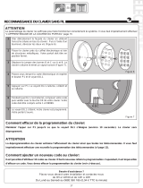 SCS Sentinel ATTENTE Le manuel du propriétaire
-
 SCS Sentinel AAM0011 Le manuel du propriétaire
-
 SCS Sentinel AAM0034Y Le manuel du propriétaire
-
 SCS Sentinel MCO0039 Le manuel du propriétaire
-
 SCS Sentinel MBA0001 Le manuel du propriétaire
-
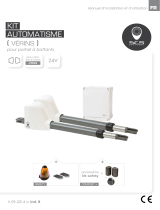 SCS Sentinel ACCESS 1 FAMILY Le manuel du propriétaire
-
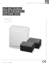 SCS Sentinel AAM0016 Le manuel du propriétaire
-
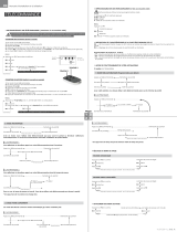 SCS Sentinel AAM0075 Le manuel du propriétaire
-
 SCS Sentinel MPD0066 Le manuel du propriétaire
-
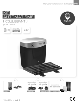 SCS Sentinel MCO0035 Le manuel du propriétaire


