SCS Sentinel AAM0034Y Le manuel du propriétaire
- Taper
- Le manuel du propriétaire

V.09-2014 ::: Ind. A
Manuel d’installation et d’utilisation FR
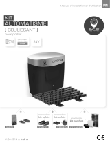
Kit
panneau solaire
pour automatisme de portail
12/24V

Fr ::: 2
FR
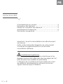
SOMMAIRE
Caractéristiques du produit ................................................... 3
Description des éléments ....................................................... 3
Fixation et connexion des éléments ..................................... 4
Avertissements à respecter .................................................... 6
Déclaration de garantie ........................................................ 7
Important : Avant toute installation lire attentivement
ce manuel.
Cette notice fait partie intégrante de votre produit.
Conservez-la soigneusement en vue de toute
consultation ultérieure.
Avertissements généraux
La mise en œuvre, les connections électriques et les
réglages doivent être effectués dans les règles de l’art
par une personne qualiée et spécialisée.
L’utilisateur de ce système est responsable et se doit
de vérier et de respecter les normes et les lois en
vigueur dans le pays d’utilisation.

Fr ::: 3
FR
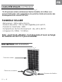
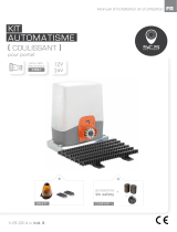
Ce kit panneau solaire extrêmement facile à installer et à utiliser vous
permet d’alimenter votre automatisme de portail en totale autonomie sans
aménagement de courant 230 Volts.
PANNEAU SOLAIRE
. Dimensions : 290 x 620 x 25 mm.
. Tension de sortie : 12V ou 24V réglable par switch.
. Puissance maximale : 20W.
. Température de fonctionnement : de -40 à +85 °C.
. Longueur du câble : 5 mètres.
Nota : avant toute utilisation, il est nécessaire d’avoir rechargé
les batteries durant 3 à 5 jours ensoleillés.
Panneau solaire
Equerres de xation
Câble de connexion
CARACTÉRISTIQUES DU PRODUIT
DESCRIPTION DES ÉLÉMENTS

Fr ::: 4
FR
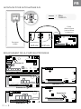
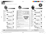
Fixer le panneau solaire sur
le support que vous souhaitez à
l’aide des deux équerres fournies.
Orientez-le vers le soleil.
1 2 3 4 5 6 7 8 9 10 1 2 3 4 5 6 7 8 9 10 1 2 3 4 5 6 7 8
P2 P3P1
FS2FS1 FS4FS3
12-24Vac+BATT-
F2
F1
DL1
ON
J2 J3J1
OFF
DL2
1 2 3 4 5 6 7 8 9 10
1 2 3
12
DL3
DL4
DL5
DL6
DL7
DL8
DL9
DL10
DL11
RV1
JP2
1 2 3
JP1
Dip switch
MONTAGE POUR AUTOMATISME 12V
Panneau
solaire
+-
Batterie
Carte
électronique
(voir schéma page
suivante)
+ : Bleu
- : Marron
FIXATION ET CONNEXION DES ÉLÉMENTS

Fr ::: 5
FR
1 2 3 4 5 6 7 8 9 10 1 2 3 4 5 6 7 8 9 10 1 2 3 4 5 6 7 8
P2 P3P1
FS2FS1 FS4FS3
12-24Vac+BATT-
F2
F1
DL1
ON
J2 J3J1
OFF
DL2
1 2 3 4 5 6 7 8 9 10
1 2 3
12
DL3
DL4
DL5
DL6
DL7
DL8
DL9
DL10
DL11
RV1
JP2
1 2 3
JP1
Dip switch
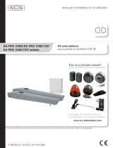
MONTAGE POUR AUTOMATISME 24V
BRANCHEMENT DE LA CARTE ELECTRONIQUE
Panneau
solaire
+-
Batterie
+-
Batterie
Carte
électronique
(voir schéma
ci-dessous)
+ : Bleu
- : Marron
1 2 3 4 5 6 7 8 9 10 20 21 22 23 24 25 26 27 28191817161514131211
P2 P3P1
FS2FS1 FS4FS3
+BATT-
F2
F1
DL1
ON
J2 J3J1
OFF
DL2
1 2 3 4 5 6 7 8 9 10
1 2 3
12
DL3
DL4
DL5
DL6
DL7
DL8
DL9
DL10
DL11
RV1
JP2
1 2 3
JP1
CTR50
DL1
RV1
1 2 3 4 5 6 7 8 9 10 11 12 13 14 15 16 FS1FS2 FS4FS3
P2
TIME
P3
PAUSE
P1
CODES
F1
PD1
C1
24Vac +BATT-
CTR51-01
CTR51
DL1
RV1
1 2 3 4 5 6 7 8 9 10 11 12 13 14 FS1FS2
FS4
12V
24V
FS3
P2
TIME
P3
PAUSE
P1
CODES
F1
RL5 RL1 RL2 RL3
R6R5
R13
RL4
PD1
C1
~24Vac~ +BATT-
CTR52-01
JP1
CTR52
P2 P3P1
DL1
RV1
JP1
JP2
FS1FS2
24V
12V
BAT T
FS4
FS3
CTR 57
- BATT+
12V
24V
JP1
ou
en
24V
CTR57
P2 P3P1
DL1
RV1
JP1
FS1FS2
- BATT+
24V
12V
BAT T
FS4
FS3
CTR 58
JP2JP3
12V
24V
JP1
ou
en
24V
CTR58
Brancher ici
Brancher ici
Brancher ici
Brancher ici
Brancher ici

• Effectuer tous les branchements avant d’utiliser le kit.
Ne sont jamais couverts par notre garantie :
• Les dommages résultant des conséquences d’une mauvaise installation
(mauvais câblage, inversion de polarité…).
• Les dommages résultant d’un usage inadéquat de l’appareil
(utilisation en contradiction avec le manuel) ou de sa modication.
• Les dommages résultant des conséquences de l’utilisation de composants
ne provenant pas de Système de Communication et de Sécurité SA.
• Les dommages dus à un défaut d’entretien, à un choc physique .
• Les dommages dus aux intempéries : grêle, foudre, vent violent etc.
• Les retours effectués sans la copie de la facture d’achat ou du ticket de caisse.
Fr ::: 6
FR
AVERTISSEMENTS À RESPECTER
Adresse : Système de Communication et de Sécurité SA FRANCE
Route de St Symphorien BP 69 85130 LES LANDES GENUSSON

V.09-2014 ::: Ind. A
Installation and user manual EN
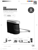
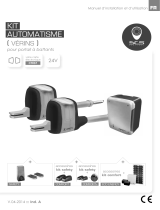
solar panel
Kit
for automated gate systems
12/24V

en ::: 8
EN
SOMMAIRE
Product characteristics ........................................................ 11
Description of the elements ................................................. 11
Attaching and connecting the elements .......................... 12
Warnings to be respected ................................................... 14
Waranty declaration ............................................................ 15
Important: Before installation read this manual.
This manual is an integral part of your product.
Store it carefully for future reference.
General Warnings
The implementation, the electrical connections and
adjustments must be made in the rules of art by a
qualied and specialized.
The user of this system is responsible and must check
and comply with the standards and laws in force in
the country of use.

en ::: 9
EN
This kit solar panel extremely easy to install and use, you can power your gate
automation development without fully independent current 230 volts.
SOLAR PANEL
. Dimensions: 290 x 620 x 25 mm.
. Output voltage: 12V or 24V adjustable by switch.
. Maximum power: 20W.
. Operating temperature: -40 to +85 ° C.
. Cable length: 5 meters.
Nota : before using, it is necessary to have recharged the batteries
for 3-5 sunny days.
FEATURES
DESCRIPTION OF THE ELEMENTS
Solar panel
Mounting brackets
Connection cable

en ::: 10
EN
Attach the solar panel by using
the two supplied brackets and by
directing panel towards the sun.
1 2 3 4 5 6 7 8 9 10 1 2 3 4 5 6 7 8 9 10 1 2 3 4 5 6 7 8
P2 P3P1
FS2FS1 FS4FS3
12-24Vac+BATT-
F2
F1
DL1
ON
J2 J3J1
OFF
DL2
1 2 3 4 5 6 7 8 9 10
1 2 3
12
DL3
DL4
DL5
DL6
DL7
DL8
DL9
DL10
DL11
RV1
JP2
1 2 3
JP1
Dip switch
MOUNTING FOR AUTOMATIC 12V
Solar panel
+-
Battery
Electronic card
(See diagram next
page)
+ : Blue
- : Brown
ATTACHING AND CONNECTING THE ELEMENTS

en ::: 11
EN
1 2 3 4 5 6 7 8 9 10 1 2 3 4 5 6 7 8 9 10 1 2 3 4 5 6 7 8
P2 P3P1
FS2FS1 FS4FS3
12-24Vac+BATT-
F2
F1
DL1
ON
J2 J3J1
OFF
DL2
1 2 3 4 5 6 7 8 9 10
1 2 3
12
DL3
DL4
DL5
DL6
DL7
DL8
DL9
DL10
DL11
RV1
JP2
1 2 3
JP1
Dip switch
MOUNTING FOR AUTOMATIC 24V
CONNECTING THE ELECTRONIC CARD
Solar panel
+-
Battery
+-
Battery
Electronic card
(See diagram under)
+ : Blue
- : Brown
1 2 3 4 5 6 7 8 9 10 20 21 22 23 24 25 26 27 28191817161514131211
P2 P3P1
FS2FS1 FS4FS3
+BATT-
F2
F1
DL1
ON
J2 J3J1
OFF
DL2
1 2 3 4 5 6 7 8 9 10
1 2 3
12
DL3
DL4
DL5
DL6
DL7
DL8
DL9
DL10
DL11
RV1
JP2
1 2 3
JP1
CTR50
DL1
RV1
1 2 3 4 5 6 7 8 9 10 11 12 13 14 15 16 FS1FS2 FS4FS3
P2
TIME
P3
PAUSE
P1
CODES
F1
PD1
C1
24Vac +BATT-
CTR51-01
CTR51
DL1
RV1
1 2 3 4 5 6 7 8 9 10 11 12 13 14 FS1FS2
FS4
12V
24V
FS3
P2
TIME
P3
PAUSE
P1
CODES
F1
RL5 RL1 RL2 RL3
R6R5
R13
RL4
PD1
C1
~24Vac~ +BATT-
CTR52-01
JP1
CTR52
P2 P3P1
DL1
RV1
JP1
JP2
FS1FS2
24V
12V
BAT T
FS4
FS3
CTR 57
- BATT+
12V
24V
JP1
ou
en
24V
CTR57
P2 P3P1
DL1
RV1
JP1
FS1FS2
- BATT+
24V
12V
BAT T
FS4
FS3
CTR 58
JP2JP3
12V
24V
JP1
ou
en
24V
CTR58
Connect here
Connect here
Connect here
Connect here
Connect
here

en ::: 12
EN
• Make all connections before using the kit.
Never covered by our warranty:
• Damage resulting from the consequences of improper installation
(bad wiring, reverse polarity ...).
• Damage resulting from improper use of the device (use in contradiction
with the manual) or its modication.
• Damage resulting from the consequences of the use of components
from outside Système de Communication et de Sécurité SA.
• Damage due to a lack of maintenance, physical shock.
• Damage due to weather: hail, lightning, wind etc...
• Returns without a copy of the invoice or receipt.
WARNINGS TO BE RESPECTED
Adress : Système de Communication et de Sécurité SA FRANCE
Route de St Symphorien BP 69 85130 LES LANDES GENUSSON
-
 1
1
-
 2
2
-
 3
3
-
 4
4
-
 5
5
-
 6
6
-
 7
7
-
 8
8
-
 9
9
-
 10
10
-
 11
11
-
 12
12


SCS Sentinel AAM0034Y Le manuel du propriétaire
- Taper
- Le manuel du propriétaire
dans d''autres langues
- English: SCS Sentinel AAM0034Y Owner's manual
Documents connexes
-
 SCS Sentinel AAM0011 Le manuel du propriétaire
-
 SCS Sentinel MCO0039 Le manuel du propriétaire
-
 SCS Sentinel AAM0086 Le manuel du propriétaire
-
 SCS Sentinel MVE0018 Le manuel du propriétaire
-
 SCS Sentinel MCO0035 Le manuel du propriétaire
-
 SCS Sentinel MBA0026 Le manuel du propriétaire
-
 SCS Sentinel 3760074131273 Le manuel du propriétaire
-
 SCS Sentinel MVE0033 Le manuel du propriétaire
-
 SCS Sentinel 3760074131204 Le manuel du propriétaire