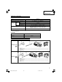
Hikoki DH 24DVA Manuel utilisateur
- Catégorie
- Outils électroportatifs
- Taper
- Manuel utilisateur
Ce manuel convient également à

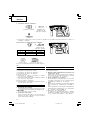
Variable speed
DH 24DVA
Cordless Rotary Hammer
Akku-bohrhammer
Perforateur percussion à batterie
Martello perforatore a batteria
Snoerloze boorhamer
Martillo perforador a batería
Martelo perfurador a bateria
™Ê˘ÚÔ‰Ú··ÓÔ ÂÚÈÛÙÚÔÊÈÎÔ Ì·Ù·ÚÈ·˜
Read through carefully and understand these instructions before use.
Diese Anleitung vor Benutzung des Werkzeugs sorgfältig durchlesen und verstehen.
Lire soigneusement et bien assimiler ces instructions avant usage.
Prima dell’uso leggere attentamente e comprendere queste instruzioni.
Deze gebruiksaanwijzing s.v.p. voor gebruik zorgvuldig doorlezen.
Leer cuidadosamente y comprender estas instrucciones antes del uso.
Antes de usar, leia com cuidado para assimilar estas instruções.
∆ιαάστε πρσεκτικά και κατανήσετε αυτές τις δηγίες πριν τη ρήση.
Handling instructions
Bedienungsanleitung
Mode d’emploi
Instruzioni per l’uso
Gebruiksaanwijzing
Instrucciones de manejo
Instruções de uso
δηγίες ειρισµύ
001CoverF_DH24DVA_WE 11/27/08, 13:361

1
1
9
7
6
1 2
4
6
8
3
5
7
7
6
5
A
0
B
C
D
3
4
8
0
A
C
E
1
2
I
H
F
G
J
00Table_DH24DVA_WE 11/27/08, 13:361

2
9 10
12
11
15
14
13
16
Y
Z
c
[ ]T
OP
SR
(a)L (b)M
(c)N
Q
V
U
A
B
W
X
[
B
C
=
\
B
\
[
`
a
V
C
b
K
K
K
C
00Table_DH24DVA_WE 11/27/08, 13:362

3
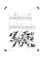
English Deutsch Français Italiano
Rechargeable battery Batterie Batterie rechargeable Batteria ricaricabile
Latch Schnapper Loquet Fermo
Guide rail of batery
Führungsschiene der Batterie
Rail guide de la batterie
Binario guida della batteria
Push Drücken Pousser Spingere
Housing Gehäuse Boîtier Alloggiamento
Pull out Herausziehen Tirer vers l’extérieur Estrarre
Insert Einsetzen Insérer Inserire
Guide rail of housing
Führungsschiene des Gehäuses
Rail guide du logement
Binario guida dell
’
alloggiamento
Pilot lamp Kontrollampe Lampe témoin Spia
Drill bit Bohrer Foret de perçage Punta del trapano
Part of SDS-plus shank Teil des SDS-plus Schaftes
Elément de la tige SDS plus
Parte dell’asta SDS plus
Front cap Vordere Abdeckung Capuchon avant Protezione davanti
Grip Spannbacke Attache coulissante Presa davanti
Dust cup Staubschale Godet a poussière Contenitore a polvere
Dust collector (B) Staubfang (B) Collecteur à poussière (B) Camera a polvere (B)
Change lever Wechselknopf Bouton de changement Rotella di cambio
“ ” mark “ ” zeichen Repère “ ” Contrassegno “ ”
“ ” mark “ ” zeichen Repère “ ” Contrassegno “ ”
“ ” mark “ ” zeichen Repère “ ” Contrassetgno “ ”
“ ” mark “ ” zeichen Repère “ ” Contrassegno “ ”
Push button Druckknopf Poussoir Tasto da premere
Forward rotation Vorwärtsdrehung Rotation avant Rotazione in avanti
Reverse rotation Rückwärtsdrehung Rotation inverse Rotazione indietro
Does not rotate Keine Drehung Aucune rotation Non ruota
Push the
R
side Die
R
Seite drücken Pousser sur le côté
R
Spingere il lato
R
Push the
L
side Die
L
Seite drücken Pousser sur le côté
L
Spingere il lato
L
Center position Mittenposition Position médiane Posizione centrale
R
indication
R
Anzeige Indication
R
Indicazione
R
L
indication
L
Anzeige Indication
L
Indicazione
L
Diagram seen from the Die Zeichnung ist von der
Schéma, côté poignée
Diagramma visto dal lato
handle side
Handgriffseite aus gesehen
della maniglia
Drill chuck Bohrfutter Mandrin porte-feret Mandrino
Chuck adaptor Bohrutteradapter Raccord de mandrin Adattatore per mandrino
Depth gauge Tiefenmesser Jauge de profondeur Calibro profondità
Mounting hole Befestigungsöffnung Orifice de montage
Foro d’inserimento della
bacchetta di arresto
Side handle Handgriff Poignée laterale Laterale
Bit Bohrerspitzen Mèche Punta
Socket Fassung Prise Presa
Taper shank adapter Kegelschaftadapter Raccord de queue conique
Adattatore per gambo conico
Cotter Dorn Clavette Coppiglia
Rest Auflage Support Appoggio
Shift knob Schaltknopf Bouton de changement Manopola del cambio
“POWER“ mode „POWER”-Modus
Mode “POWER” (puissance) Modo “POWER”
“SAVE“ mode „SAVE“-Modus Mode
“
SAVE
”
(économie) Modo “SAVE”
1
2
3
4
5
6
7
8
9
0
A
B
C
D
E
F
G
H
I
J
K
L
M
N
O
P
Q
R
S
T
U
V
W
X
Y
Z
[
\
]
`
a
b
c
00Table_DH24DVA_WE 11/27/08, 13:363

4
Nederlands Español Português Ελληνικά
Oplaadbare batterij Baterîa recargable Bateria recarregável
Επαναρτιµενη µπαταρία
Vergrendeling Enganche Lingüeta Μάνδαλ
Geleider batterij Riel de guía de la batería Guia da grade da bateria
Τριγραµµή της µπαταρίας
Drukken Presionar Apertar Σπρώε
Behuizing Carcasa Cárter Περίληµα
Uittrekken Sacar Retirar Τραήτε έω
Insteken Insertar Inserir Εισωρήστε
Geleiderail behuizing Riel de guía de la carcasa
Trilho de segurança do cárter
Τριγραµµή τυ περιλήµατς
Kontrolelampje Lámpara piloto Lâmpada piloto ∆κιµαστική λάµπα
Boorstuk Broca Broca Λεπίδα τρυπανιύ
Onderdeel van SDS Plus schacht
Parte del SDS más vástago
Cabo de peça SDS-plus
Τµήµα τυ SDS-plus στελέυς
Voorkap Cubierta frontal Tampa da frente Μπρστιν περίληµα
Greep Sujetador Mordente Λαή
Stofvangkap Copa de polvo Receptáculo para poeira Κύπελλ σκνης
Stofverzamelaar (B) Colector de polvo (B) Coletor de poeira (B) Συλλέκτης σκνης (Β)
Omstelknop Perilla de cambio Seletor Μλς αλλαγής
“ ”-markering Marca “ ” Marca “ ”“” σηµάδι
“ ”-markering Marca “ ” Marca “ ”“” σηµάδι
“ ”-markering Marca “ ” Marca “ ”“ ” σηµάδι
“ ”-markering Marca “ ” Marca “ ”“”σηµάδι
Druktoets Pulsador Botão de pressão Κυµπί ώθησης
Voorwaartse draairichting Rotación hacia la derecha Rotação para frente
Πρς τα εµπρς περιστρή
Terugwaartse draairichting
Rotación hacia la izquierda Rotação inversa Αντίστρη περιστρή
Draait niet No gira Nenhuma rotação ∆εν περιστρέεται
Druk aan de
R
kant Presione el lado
R
Apertar o lado
R
Σπρώετε την
R
πλευρά
Druk aan de
L
kant Presione el lado
L
Apertar o lado
L
Σπρώετε την
L
πλευρά
Middenpositie Posición central Posição intermediária Κεντρική θέση
R
aanduiding Indicación
R
Indicação
R R
ένδειη
L
aanduiding Indicación
L
Indicação
L L
ένδειη
Schema, gezien vanaf de Diagrama visto desde el Diagrama visto pelo
∆ιάγραµµα πυ λέπεται απ
handgreep-kant lado del asa lado do cabo
την πλευρά τυ ερυλιύ
Boorkop Portabrocas Mandril Σικτήρας τρυπανιύ
Boorkopadapter Adaptador del portabrocas Adaptador do mandril
Πρσαρµγέας σικτήρα
Diepte-maatlat Calibre de profundidad Sonda Μετρητής άθυς
Montagegat Agujero de montaje Orifício de montagem Τρύπα στερέωσης
Zijgreep Mango lateral Empunhadura lateral Πλευρική λαή
Boorstuk Broca Palhetão Λεπίδα
Aansluithus Cubo Encaixe Υπδή
Vernauwde
Adaptador de la espiga Adaptador de cabo cônico
Κωνικς πρσαρµγέας
schachtadaptor στελέυς
Cotter Chaveta Cavilha Κτης
Steun Apoyo Suporte Στήριγµα
Schakelknop Perilla de cambio Seletor Κυµπί αλλαγής
“POWER” stand Modo “POWER” Modo “POWER“ Θέση “POWER”
“SAVE” stand Modo “SAVE” Modo “SAVE” Θέση “SAVE”
1
2
3
4
5
6
7
8
9
0
A
B
C
D
E
F
G
H
I
J
K
L
M
N
O
P
Q
R
S
T
U
V
W
X
Y
Z
[
\
]
`
a
b
c
00Table_DH24DVA_WE 11/27/08, 13:364

5
Symbols
WARNING
The following show
symbols used for the
machine. Be sure that
you understand their
meaning before use.
Symbole
WARNUNG
Die folgenden Symbole
werden für diese Maschine
verwendet. Achten Sie
darauf, diese vor der
Verwendung zu verstehen.
Symboles
AVERTISSEMENT
Les symboles suivants
sont utilisés pour l’outil.
Bien se familiariser avec
leur signification avant
d’utiliser l’outil.
Simboli
AVVERTENZA
Di seguito mostriamo i
simboli usati per la
macchina. Assicurarsi di
comprenderne il
significato prima dell’uso.
Read all safety
warnings and all
instructions.
Failure to follow the
warnings and
instructions may result
in electric shock, fire
and/or serious injury.
Lesen Sie sämtliche
Sicherheitshinweise und
Anweisungen durch.
Wenn die Warnungen und
Anweisungen nicht befolgt
werden, kann es zu
Stromschlag, Brand und/
oder ernsthaften
Verletzungen kommen.
Lire tous les avertissements
de sécurité et toutes les
instructions.
Tout manquement à observer
ces avertissements et
instructions peut engendrer
des chocs électriques, des
incendies et/ou des blessures
graves.
Leggere tutti gli avvertimenti
di sicurezza e tutte le
istruzioni.
La mancata osservanza degli
avvertimenti e delle istruzioni
potrebbe essere causa di
scosse elettriche, incendi e/o
gravi lesioni.
Symbolen
WAARSCHUWING
Hieronder staan symbolen
afgebeeld die van toepassing
zijn op deze machine. U
moet de betekenis hiervan
begrijpen voor gebruik.
Símbolos
ADVERTENCIA
A continuación se muestran
los símbolos usados para la
máquina. Asegúrese de
comprender su significado
antes del uso.
Símbolos
AVISO
A seguir aparecem os
símbolos utilizados pela
máquina. Assimile bem
seus significados antes
do uso.
Lees alle waarschuwingen en
instructies aandachtig door.
Nalating om de
waarschuwingen en
instructies op te volgen kan in
een elektrische schok, brand
en/of ernstig letsel resulteren.
Lea todas las instrucciones y
advertencias de seguridad.
Si no se siguen las
advertencias e instrucciones,
podría producirse una
descarga eléctrica, un
incendio y/o daños graves.
Leia todas as instruções e
avisos de segurança.
Se não seguir todas as
instruções e os avisos, pode
provocar um choque eléctrico,
incêndio e/ou ferimentos
graves.
Only for EU countries
Do not dispose of electric
tools together with household
waste material!
In observance of European
Directive 2002/96/EC on waste
electrical and electronic
equipment and its
implementation in accordance
with national law, electric
tools that have reached the
end of their life must be
collected separately and
returned to an
environmentally compatible
recycling facility.
Nur für EU-Länder
Werfen Sie Elektrowerkzeuge
nicht in den Hausmüll!
Gemäss Europäischer
Richtlinie 2002/96/EG über
Elektro- und Elektronik-
Altgeräte und Umsetzung in
nationales Recht müssen
verbrauchte Elektrowerkzeuge
getrennt gesammelt und einer
umweltgerechten
Wiederververtung zugeführt
werden.
Pour les pays européens
uniquement
Ne pas jeter les appareils
électriques dans les ordures
ménagères!
Conformément à la directive
européenne 2002/96/EG relative
aux déchets d’équipements
électriques ou électroniques
(DEEE), et à sa transposition
dans la législation nationale, les
appareils électriques doivent
être collectés à part et être
soumis à un recyclage
respectueux de
l’environnement.
Solo per Paesi UE
Non gettare le
apparecchiature elettriche tra i
rifiuti domestici.
Secondo la Direttiva Europea
2002/96/CE sui rifiuti di
apparecchiature elettriche ed
elettroniche e la sua
attuazione in conformità alle
norme nazionali, le
apparecchiature elettriche
esauste devono essere
raccolte separatamente, al fine
di essere reimpiegate in modo
eco-compatibile.
Alleen voor EU-landen
Geef elektrisch gereedschap
niet met het huisvuil mee!
Volgens de Europese richtlijn
2002/96/EG inzake oude
elektrische en elektronische
apparaten en de toepassing
daarvan binnen de nationale
wetgeving, dient gebruikt
elektrisch gereedschap
gescheiden te worden
ingezameld en te worden
afgevoerd naar een recycle
bedrijf dat voldoet aan de
geldende milieu-eisen.
Apenas para países da UE
Não deite ferramentas
eléctricas no lixo doméstico!
De acordo com a directiva
europeia 2002/96/CE sobre
ferramentas eléctricas e
electrónicas usadas e a
transposição para as leis
nacionais, as ferramentas
eléctricas usadas devem ser
recolhidas em separado e
encaminhadas a uma
instalação de reciclagem dos
materiais ecológica.
Sólo para países de la Unión
Europea
¡No deseche los aparatos
eléctricos junto con los residuos
domésticos!
De conformidad con la Directiva
Europea 2002/96/CE sobre
residuos de aparatos eléctricos y
electrónicos y su aplicación de
acuerdo con la legislación
nacional, las herramientas
eléctricas cuya vida útil haya
llegado a su fin se deberán recoger
por separado y trasladar a una
planta de reciclaje que cumpla con
las exigencias ecológicas.
™‡Ì‚ÔÏ·
¶ƒ√™√Ã∏
Τα παρακάτω δείνυν τα
σύµλα πυ ρησιµπιύνται
στ µηάνηµα. Βεαιωθείτε τι
κατανείτε τη σηµασίας τυς
πριν τη ρήση.
¢È·‚¿˙ÂÙ fiϘ ÙȘ
ÚÔÂȉÔÔÈ‹ÛÂȘ ·ÛÊ·Ï›·˜ ηÈ
fiϘ ÙȘ Ô‰ËÁ›Â˜.
Η µη τήρηση των πρειδπιήσεων
και δηγιών µπρεί να πρκαλέσει
ηλεκτρπληία, πυρκαγιά και/ή
σαρ τραυµατισµ.
Mvo για τις ώρες της EE
Mηv πετάτε τα ηλεκτρικά
εργαλεία στov κάδo oικιακώv
απoρριµµάτωv!
Σύµωvα µε τηv εuρωπαϊκή
oδηγία 2002/96/EK περί
ηλεκτρικώv και ηλεκτρovικώv
σuσκεuώv και τηv
εvσωµάτωσή της στo εθvικ
δίκαιo, τα ηλεκτρικά
εργαλεία πρέπει vα
σuλλέγovται εωριστά και
vα επιστρέovται για
αvακύκλωση µε τρπo ιλικ
πρoς τo περιάλλov.
00Table_DH24DVA_WE 11/27/08, 13:365

6
English
GENERAL POWER TOOL SAFETY WARNINGS
WARNING
Read all safety warnings and all instructions.
Failure to follow the warnings and instructions may result
in electric shock, fire and/or serious injury.
Save all warnings and instructions for future reference.
The term “power tool” in the warnings refers to your
mains-operated (corded) power tool or battery-operated
(cordless) power tool.
1) Work area safety
a) Keep work area clean and well lit.
Cluttered or dark areas invite accidents.
b) Do not operate power tools in explosive
atmospheres, such as in the presence of
flammable liquids, gases or dust.
Power tools create sparks which may ignite the
dust or fumes.
c) Keep children and bystanders away while
operating a power tool.
Distractions can cause you to lose control.
2) Electrical safety
a) Power tool plugs must match the outlet.
Never modify the plug in any way.
Do not use any adapter plugs with earthed
(grounded) power tools.
Unmodified plugs and matching outlets will
reduce risk of electric shock.
b) Avoid body contact with earthed or grounded
surfaces, such as pipes, radiators, ranges and
refrigerators.
There is an increased risk of electric shock if
your body is earthed or grounded.
c) Do not expose power tools to rain or wet
conditions.
Water entering a power tool will increase the
risk of electric shock.
d) Do not abuse the cord. Never use the cord for
carrying, pulling or unplugging the power tool.
Keep cord away from heat, oil, sharp edges or
moving parts.
Damaged or entangled cords increase the risk
of electric shock.
e) When operating a power tool outdoors, use an
extension cord suitable for outdoor use.
Use of a cord suitable for outdoor use reduces
the risk of electric shock.
f) If operating a power tool in a damp location
is unavoidable, use a residual current device
(RCD) protected supply.
Use of an RCD reduces the risk of electric shock.
3) Personal safety
a) Stay alert, watch what you are doing and use
common sense when operating a power tool.
Do not use a power tool while you are tired or
under the influence of drugs, alcohol or medication.
A moment of inattention while operating power
tools may result in serious personal injury.
b) Use personal protective equipment. Always wear
eye protection.
Protective equipment such as dust mask, non-
skid safety shoes, hard hat, or hearing protection
used for appropriate conditions will reduce
personal injuries.
c) Prevent unintentional starting. Ensure the switch
is in the off-position before connecting to power
source and/or battery pack, picking up or
carrying the tool.
Carrying power tools with your finger on the
switch or energising power tools that have the
switch on invites accidents.
d) Remove any adjusting key or wrench before
turning the power tool on.
A wrench or a key left attached to a rotating part
of the power tool may result in personal injury.
e) Do not overreach. Keep proper footing and
balance at all times.
This enables better control of the power tool in
unexpected situations.
f) Dress properly. Do not wear loose clothing or
jewellery. Keep your hair, clothing and gloves
away from moving parts.
Loose clothes, jewellery or long hair can be
caught in moving parts.
g) If devices are provided for the connection of
dust extraction and collection facilities, ensure
these are connected and properly used.
Use of dust collection can reduce dust related hazards.
4) Power tool use and care
a) Do not force the power tool. Use the correct
power tool for your application.
The correct power tool will do the job better and
safer at the rate for which it was designed.
b) Do not use the power tool if the switch does
not turn it on and off.
Any power tool that cannot be controlled with
the switch is dangerous and must be repaired.
c) Disconnect the plug from the power source
and/or the battery pack from the power tool
before making any adjustments, changing
accessories, or storing power tools.
Such preventive safety measures reduce the risk
of starting the power tool accidentally.
d) Store idle power tools out of the reach of children
and do not allow persons unfamiliar with the
power tool or these instructions to operate the
power tool.
Power tools are dangerous in the hands of
untrained users.
e) Maintain power tools. Check for misalignment
or binding of moving parts, breakage of parts
and any other condition that may affect the
power tools operation.
If damaged, have the power tool repaired before
use.
Many accidents are caused by poorly maintained
power tools.
f) Keep cutting tools sharp and clean.
Properly maintained cutting tools with sharp
cutting edges are less likely to bind and are
easier to control.
g) Use the power tool, accessories and tool bits
etc. in accordance with these instructions, taking
into account the working conditions and the
work to be performed.
Use of the power tool for operations different from
those intended could result in a hazardous situation.
01Eng_DH24DVA_WE 11/27/08, 13:366

7
English
5) Battery tool use and care
a) Recharge only with the charger specified by the
manufacturer.
A charger that is suitable for one type of battery
pack may create a risk of fire when used with
another battery pack.
b) Use power tools only with specifically designated
battery packs.
Use of any other battery packs may create a risk
of injury and fire.
c) When battery pack is not in use, keep it away from
other metal objects like paper clips, coins, keys,
nails, screws, or other small metal objects that can
make a connection from one terminal to another.
Shorting the battery terminals together may
cause burns or a fire.
d) Under abusive conditions, liquid may be ejected
from the battery; avoid contact. If contact
accidentally occurs, flush with water. If liquid
contacts eyes, additionally seek medical help.
Liquid ejected from the battery may cause
irritation or burns.
6) Service
a) Have your power tool serviced by a qualified repair
person using only identical replacement parts.
This will ensure that the safety of the power tool
is maintained.
PRECAUTION
Keep children and infirm persons away.
When not in use, tools should be stored out of reach of
children and infirm persons.
CORDLESS ROTARY HAMMER SAFETY WARNINGS
1. Wear ear protectors
Exposure to noise can cause hearing loss.
2. Use auxiliary handles supplied with the tool.
Loss of control can cause personal injury.
3. When using this unit continuously, the unit may
overheat, leading to damage in the motor and
switch. Please leave it without using it for
approximately 15 minutes.
4. When drilling in wall, floor or ceiling, check for
buried electric power cord, etc.
5. Bring the battery to the shop from which it was
purchased as soon as the post-charging battery
life becomes too short for practical use. Do not
dispose of the exhausted battery.
6. Do not touch the bit during or immediately after
operation. The bit becomes very hot during
operation and could cause serious burns.
7. Always hold the body handle and side handle of
the power tool firmly. Otherwise the counterforce
produced may result in inaccurate and even
dangerous operation.
8. Wear a dust mask
Do not inhale the harmful dusts generated in
drilling or chiseling operation. The dust can
endanger the health of yourself and bystanders.
9. Always charge the battery at a temperature of 0
– 40°C.
A temperature of less than 0°C will result in over
charging which is dangerous. The battery cannot
be charged at a temperature higher than 40°C.
The most suitable temperature for charging is that
of 20 – 25°C.
10. Do not use the charger continuously.
When one charging is completed, leave the charger
for about 15 minutes before the next charging of
battery.
11. Do not allow foreign matter to enter the hole for
connecting the rechargeable battery.
12. Never disassemble the rechargeable battery and
charger.
13. Never short-circuit the rechargeable battery. Short-
chircuiting the battery will cause a great electric
current and overheat. It results in burn or damage
to the battery.
14. Do not dispose of the battery in fire.
If the battery is burnt, it may explode.
15. Do not insert object into the air ventilation slots
of the charger.
Inserting metal objects or inflammables into the
charger air ventilation slots will result in electrical
shock hazard or damaged charger.
16. Using an exhausted battery will damage the charger.
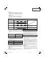
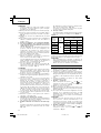
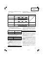
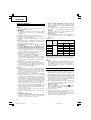
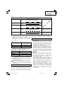
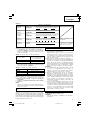
SPECIFICATIONS
POWER TOOL
Model DH24DVA
No-load speed Save/Power 0 – 520 min
–1
/ 0 – 1050 min
–1
Full-load impact rate Save/Power 0 – 2200 min
–1
/ 0 – 4500 min
–1
Concrete 24 mm
Capacity
Drilling Steel 13 mm
Wood 30 mm
Driving Wood screw 6.2 mm (diameter) × 40 mm (length)
EB2420: Ni-Cd 24 V (2.0 Ah 20 cells)
Rechargeable battery EB2430HA: Ni-MH 24 V (3.0 Ah 20 cells)
EB2433X: Ni-MH 24 V (3.3 Ah 20 cells)
Weight 4.1 kg
䡬 Do not use the “SAVE“ mode when boring holes with the wood drill. There is a likelihood that the motor
will burn out.
CHARGER
Model UC24YFB
Charging voltage 24 V
Weight 0.6 kg
01Eng_DH24DVA_WE 11/27/08, 13:367

8
English
DH24DVA (BFK)
(HFK)
(XFK)
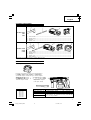
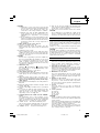
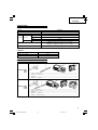
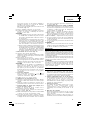
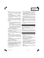
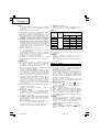
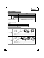
STANDARD ACCESSORIES
1 Side handle ...................................................................................................................... 1
2 Depth gauge .................................................................................................................... 1
3 Charger .............................................................................................................................. 1
4 Plastic case ....................................................................................................................... 1
DH24DVA (2BFK)
(2HFK)
(2XFK)
1 Side handle ...................................................................................................................... 1
2 Depth gauge .................................................................................................................... 1
3 Charger .............................................................................................................................. 1
4 Plastic case ....................................................................................................................... 1
5 Extra battery .................................................................................................................... 1
Standard accessories are subject to change without notice.
1
2
3
4
5
2
4
3
1
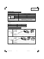
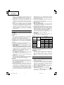
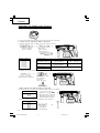
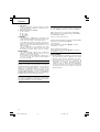
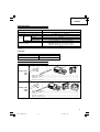
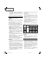
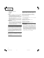
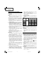
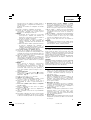
OPTIONAL ACCESSORIES (sold separately)
1. Battery (EB2420, EB2430HA, EB2433X)
It may be convenient to prepare some extra batteries.
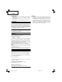
2. Drilling anchor holes (rotation + hammering)
䡬 Drill bit (taper shank) and taper shank adapter
Taper mode Applicable drill bit
Morse taper (No. 1) Drill bit (taper shank) 11.0 – 17.5 mm
Morse taper (No. 2) Drill bit (taper shank) 21.5 mm
A-taper
Taper shank adapter formed A-taper or B-taper
B-taper
is provided as an optional accessory, but drill bit
for it is not provided.
Outer diameter
11.0 mm
12.3 mm
12.7 mm
14.3 mm
14.5 mm
17.5 mm
21.5 mm
Taper shank adapter
(SDS plus shank)
Drill bit (taper shank)
Cotter
01Eng_DH24DVA_WE 11/27/08, 13:368

9
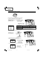
English
13 mm Hammer
Drill Chuck
(SDS plus shank)
Impact Drill Application
Straight Shank Bit
()
䡬 13 mm Hammer Drill chuck and Chuck wrench
Anchor size
W1/4"
W5/16"
W3/8"
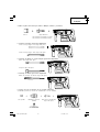
3. Anchor setting (rotation + hammering)
䡬 Anchor setting adapter (for rotary hammer)
Anchor setting adapter
(for rotary hammer)
(SDS plus shank)
Chuck wrench
䡬 Anchor setting adapter (for manual hammer)
Anchor size
W1/4"
W5/16"
W3/8"
W1/2"
W5/8"
Anchor setting adapter
(for manual hammer)
4. Bolt placing operation with Chemical Anchor. (rotation + hammering)
(SDS-plus shank)
12.7 mm Chemical Anchor Adapter
19 mm Chemical Anchor Adapter
Standard socket
on the market
( )
5. Demolishing operation (Hammering only)
Bull point (Round type) (SDS-plus shank)
Bull point (Square type) (SDS-plus shank)
01Eng_DH24DVA_WE 11/27/08, 13:369

10
English
6. Groove digging and edging (Hammering only)
Cold chisel (SDS-plus shank)
Cutter (SDS-plus shank)
7. Grooving (Hammering only)
Grooving chisel (SDS-plus shank)
Special
screw
8. Drilling holes and driving screws (rotation only)
䡬 Drill chuck, chuck adapter (G) and chuck wrench
Drill chuck (13VLR)
Chuck wrench
Chuck adapter (G)
(SDS plus shank)
䡬 13 mm drill chuck ass’y (include chuck wrench ass’y) and chuck (for drilling in steel or wood).
9. Drilling holes (rotation only)
Drill chuck (13VLA)
Chuck wrench
Chuck adapter (D)
(SDS plus shank)
01Eng_DH24DVA_WE 11/27/08, 13:3610

11
English
10. Driving Screws (rotation only)
Bit No. Screw Size Length
No. 2 3–5 mm 25 mm
No. 3 5–8 mm 25 mm
11. Dust cup, Dust collector (B)
Dust cup
Dust collector (B)
Bit
No.
Chuck adapter (D)
(SDS plus shank)
Optional accessories are subject to change without notice.
APPLICATIONS
Rotation and hammering function
䡬 Drilling anchor holes
䡬 Drilling holes in concrete
䡬 Drilling holes in tile
Rotation only function
䡬 Drilling in steel or wood
(with optional accessories)
䡬 Tightening machine screws, wood screws
(with optional accessories)
Hammering only function
䡬 Light-duty chiselling of concrete, groove digging
and edging.
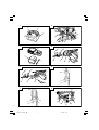
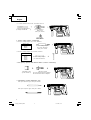
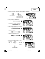
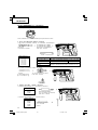
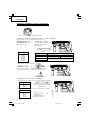
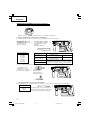
BATTERY REMOVAL/INSTALLATION
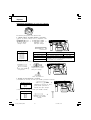
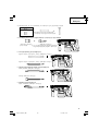
1. Battery removal
Hold the handle tightly and push the battery latches
to remove the battery (see Figs. 1 and 2).
CAUTION:
Never short-circuit the battery.
2. Battery installation
Insert the battery aligning both guide rail of battery
and body. Make sure the battery is fixed firmly.
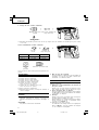
CHARGING
Before using the power tool, charge the battery as follows.
1. Connect the charger’s power cord to a receptacle.
When the power cord is connected, the charger’s
pilot lamp will blink in red. (At 1-second intervals).
2. Insert the battery into the charger.
Insert the battery into the charger as shown in Fig.
3. Make sure the battery is fully seated in the
charger.
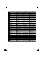
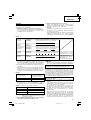
3. Charging
When inserting a battery in the charger, charging
will commence and the pilot lamp will light
continuously in red.
When the battery becomes fully recharged, the pilot
lamp will blink in red. (At 1-second intervals.) (See
Table 1)
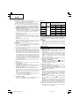
(1) Pilot lamp indication
The indications of the pilot lamp will be as shown
in Table 1, according to the condition of the charger
or the rechargeable battery.
01Eng_DH24DVA_WE 11/27/08, 13:3611

12
English
(2) Regarding the temperatures of the rechargeable
battery.
The temperatures for rechargeable batteries are as
shown in the table 2, and batteries that have become
hot should be cooled for a while before being
recharged.
Table 2
(3) Regarding recharging time
Depending on the type of the battery, the charging
time will become as shown in Table 3.
Table 3 Charging time (At 20°C)
NOTE: The charging time may vary according to ambient
temperature and power source voltage.
4. Disconnect the charger’s power cord from the
receptacle.
5. Hold the charger firmly and pull out the battery.
NOTE:
After operation, pull out batteries from the charger
first, and then keep the batteries properly.
Regarding electric discharge in case of new batteries,
etc.
As the internal chemical substance of new batteries and
batteries that have not been used for an extended period
is not activated, the electric discharge might be low when
using them the first and second time. This is a temporary
phenomenon, and normal time required for recharging
will be restored by recharging the batteries 2–3 times.
Lights for 0.5 seconds. Does not light for 0.5
seconds. (off for 0.5 seconds)
Lights continuously
Lights for 0.5 seconds. Does not light for 0.5
seconds. (off for 0.5 seconds)
Lights for 0.1 seconds. Does not light for 0.1
seconds. (off for 0.1 seconds)
Lights continuously
Before charging
While charging
Charging complete
Charging impossible
Charging impossible
Blinks
(RED)
Lights
(RED)
Blinks
(RED)
Lights
(GREEN)
Malfunction in the
battery or the charger
The battery temperature
is high, making recharg-
ing impossible.
Table 1
Indications of the pilot lamp
Temperatures at
Battery type which the battery
can be recharged
EB2420 –5°C – 60°C
EB2430HA, EB2433X 0°C – 45°C
How to make the batteries perform longer
(1) Recharge the batteries before they become
completely exhausted.
When you feel that the power of the tool becomes
weaker, stop using the tool and recharge its battery.
If you continue to use the tool and exhaust the
electric current, the battery may be damaged and
its life will become shorter.
(2) Avoid recharging at high temperatures.
A rechargeable battery will be hot immediately after
use. If such a battery is recharged immediately after
use, its internal chemical substance will deteriorate,
and the battery life will be shortened. Leave the
battery and recharge it after it has cooled for a
while.
CAUTION:
䡬 If the battery has been heated right after operation
(or due to sunlight, etc.), the charger’s pilot lamp
may not light in red. In such a case, first let the
battery cool, then start charging.
䡬 When the pilot lamp flikers in red (at 0.2–second
intervals), check for and take out any foreign objects
in the charger’s battery installation hole. If there are
no foreign objects, it is probable that the battery
or charger is malfunctioning. Take it to your
authorized Service Center.
䡬 Since the built-in micro computer takes about 3
seconds to confirm that the battery being charged
with UC24YFB is taken out, wait for a minimum of
3 seconds before reinserting it to continue charging.
If the battery is reinserted within 3 seconds, the
battery may not be properly charged.
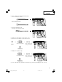
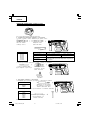
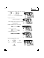
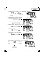
PRIOR TO OPERATION
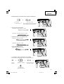
1. Mounting the drill bit (Fig. 4, 5)
CAUTION:
To prevent accidents, make sure to turn the switch
off.
NOTE:
When using tools such as drill bits, etc., make sure
to use the genuine parts designated by our company.
Battery type Recharging time
EB2420 Approx. 50 min.
EB2430HA Approx. 70 min.
EB2433X Approx. 75 min.
01Eng_DH24DVA_WE 11/27/08, 13:3612

13
English
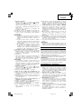
Table 4
These data are for the referential values. The number of
holes that can be drilled varies according to the sharpness
of the used bit or the conditions of the concrete being
drilled.
CAUTION:
When using this unit continuously, the unit may
overheat, leading to damage in the motor and switch.
Please leave it without using it for approximately
15 minutes.
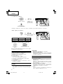
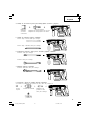
HOW TO USE
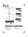
1. Switch operation
䡬 When the switch trigger is depressed, the tool
rotates. When the switch trigger is released, the
tool stops.
䡬 The rotational speed of the rotary hammer can be
controlled by varying the amount that the switch
trigger is pulled. Speed is low when the switch
trigger is pulled slightly and increases as the switch
trigger is pulled more.
䡬 When releasing the switch trigger, the brake will
be applied for immediate stopping.
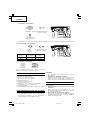
2. Rotation + Hammering
Align the “
” mark with the “ ” mark by
rotating the change lever to set the “Rotation +
Hammering” function. (Fig. 8)
(1) Mount the drill bit.
(2) Pull the trigger switch after applying the drill bit
tip to the drilling position. (Fig. 10)
(3) Pushing the rotary hammer forcibly is not necessary
at all. Pushing slightly so that drill dust comes out
gradually is just sufficient.
CAUTION:
When the drill bit touches construction iron bar, the
bit will stop immediately and the rotary hammer
will react to revolve. Therefore please grip the side
handle and handle tightly as shown in Fig. 10.
3. Rotation only
Align the “
” mark with the “ ” mark by rotating
the change lever to set the “Rotation only” function.
(Fig. 8)
To drill a wood or metal material using the optional
drill chuck and chuck adapter, proceed as follows.
Installing drill chuck and chuck adapter: (Fig. 11)
(1) Attach the drill chuck to the chuck adaptor.
(2) The part of the SDS-plus shank is the same as the
drill bit. Therefore, refer to the item of “Mounting
the drill bit” for attaching it.
(1) Clean the shank portion of the drill bit.
(2) Insert the drill bit in a twisting manner into the tool
holder until it latches itself. (Fig. 4)
(3) Check the latching by pulling on the drill bit.
(4) To remove the drill bit, fully pull the grip in the
direction of the arrow and pull out the drill bit.
2. Confirm that the battery is mounted correctly.
3. Installation of dust cup or dust collector (B) (Optional
accessories) (Fig. 6, Fig. 7)
When using a rotary hammer for upward drilling
operations attach a dust cup or a dust collector (B)
to collect dust or particles for easy operation.
䡬 Installing the dust cup
Use the dust cup by attaching to the drill bit as
shown in Fig. 6.
When using a bit which has big diameter, enlarge
the center hole of the dust cup with this rotary
hammer.
䡬 Installing dust collector (B)
When using dust collector (B), insert dust collector
(B) from the tip of the bit by aligning it to the
groove on the grip. (Fig. 7)
CAUTION:
䡬 The dust cup and dust collector (B) are for exclusive
use of concrete drilling work. Do not use them for
wood or metal drilling work.
䡬 Insert dust collector (B) completely into the chuck
part of the main unit.
䡬 When turning the rotary hammer on while dust
collector (B) is detached from a concrete surface,
dust collector (B) will rotate together with the drill
bit. Make sure to turn on the switch after pressing
dust cup on the concrete surface. When using dust
collector (B) attached to a drill bit that has more
than 190 mm of overall length, dust collector (B)
cannot touch the concrete surface and will rotate.
Therefore, please use dust collector (B) by attaching
to drill bits which have 166 mm, 160 mm, and 110
mm overall length.
䡬 Dump particles after every two or three holes when
drilling.
䡬 Please replace the drill bit after removing dust
collector (B).
4. Selecting the driver bit
Screw heads or bits will be damaged unless a bit
appropriate for the screw diameter is employed to
drive in the screws.
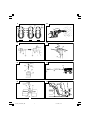
5. Confirm the direction of bit rotation (Fig. 9)
The bit rotates clockwise (viewed from the rear
side) by pushing the R-side of the push button. (Fig.
9-a)
The L-side of the push button is pushed to turn the
bit counterclockwise. (Fig. 9-b)
The motor does not rotate if the push button is set
to the center position. (Fig. 9-c)
6. Continuous drilling
The number of holes that can be drilled in concrete
after one recharge is shown in Table 4.
Possible continuous
Bit dia. Depth drilling number (holes)
(mm) (mm) EB2420 EB2430HA EB2433X
6.5 75 115 125
8.5 45 70 75
12.5 40 55 60
14.5
60
30 45 50
18 15 25 28
24 5 7 8
01Eng_DH24DVA_WE 11/27/08, 13:3613

14
English
CAUTION:
䡬 Application of force more than necessary will
not only expedite work at all, but will deteriorate
the tip edge of the drill bit and reduce the
service life of the rotary hammer in addition.
䡬 Drill bit may snap off while withdrawing the
rotary hammer from the drilled hole. For
withdrawing, it is important to use a pushing
motion.
䡬 Do not attempt to use the rotary hammer in the
rotation and striking mode with the drill chuck
and chuck adapter attached. This would seriously
shorten the service life of every component of
the machine.
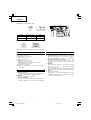
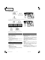
4. When driving wood screws (Fig. 13)
(1) Selecting a suitable driver bit
Employ plus-head screws, if possible, since the
driver bit easily slips off the heads of slotted-head
screws.
(2) Tightening wood screws
Prior to tightening wood screws, make pilot holes
suitable for them in the wooden board. Apply the
bit to the screw head grooves and gently drive the
screws in the holes.
CAUTION:
Exercise care in preparing a pilot hole suitable for
the wood screw taking the hardness of the wood
into consideration. Should the hole be excessively
small or shallow, requiring much power to drive
the screw into it, the thread of the wood screw may
sometimes be damaged.
5. Hammering only
Align the “
” mark with the “ ” mark by rotating
the change lever to set the “Hammering only”
function. (Fig. 8)
(1) Mount the bull point or cold chisel.
6. Using depth gauge (Fig. 12)
(1) Loosen the knob on the side handle, and insert the
depth gauge into the mounting hole on the side
handle.
(2) Adjust the depth gauge position according to the
depth of the hole and tighten the knob bolt securely.
7. How to use the drill bit (taper shank) and the taper
shank adapter
(1) Mount the taper shank adapter to the rotary hammer.
(Fig. 14)
(2) Mount the drill bit (taper shank) to the taper shank
adapter. (Fig. 14)
(3) Turn the switch ON, and drill a hole to prescribed
depth.
(4) To remove the drill bit (taper shank), insert the
cotter into the slot of the taper shank adapter and
strike the head of the cotter with a hammer
supporting on the rest. (Fig. 15)
8. Switching between the “SAVE“ and the “POWER“
modes
The hammering force of the hammer can be
increased or decreased to conform with intended
usage, by operating the shift knob as per Fig. 16.
Adjust the force to match the usage intended.
(1) “SAVE“ mode ... decreased hammering force
This can prevent thin drill bits which are less than
5 mm in diameter, from being bent or broken.
(2) “POWER“ mode ... increased hammering force
䡬 This can be used to speedily and efficiently drill
holes when the drill bits which are being used are
greater than 5 mm in diameter.
䡬 This can be used to drill holes into wood or metal.
CAUTION:
Do not drill holes in wood with the “SAVE“ mode.
There is a likelihood that the motor will burn out
because it can easily lock up due to the low power.
LUBRICATION
Low viscosity grease is applied to this rotary hammer so
that it can be used for a long period without replacing the
grease. Please contact the nearest service center for
grease replacement when any grease is leaking form
loosened screw.
Further use of the rotary hammer despite the grease
shortage causes damage to reduce the service life.
CAUTION:
A specific grease (FG-6A) is used with this machine,
therefore, the normal performance of the machine may
be badly affected by use of different grease. Please be
sure to let one of our service centers to undertake
replacement of the grease.
MAINTENANCE AND INSPECTION
1. Inspecting the tool
Since use of a dull tool will degrade efficiency and
cause possible motor malfunction, sharpen or
replace the tool as soon as abrasion is noted.
2. Inspecting the mounting screws
Regularly inspect all mounting screws and ensure
that they are properly tightened. Should any of the
screws be loose, retighten them immediately. Failure
to do so could result in serious hazard.
3. Maintenance of the motor
The motor unit winding is the very “heart” of the
power tool. Exercise due care to ensure the winding
does not become damaged and/or wet with oil or
water.
4. Cleaning on the outside
When the power tool is stained, wipe with a soft
dry cloth or a cloth moistened with soapy water.
Do not use chloric solvents, gasoline or paint thinner,
as they melt plastics.
5. Storage
Store the power tool in a place in which the
temperature is less than 40°C and out of reach of
children.
6. Service parts list
A: Item No.
B: Code No.
C: No. Used
D: Remarks
CAUTION:
Repair, modification and inspection of Hitachi Power
Tools must be carried out by a Hitachi Authorized
Service Center.
This Parts List will be helpful if presented with the
tool to the Hitachi Authorized Service Center when
requesting repair or other maintenance.
In the operation and maintenance of power tools,
the safety regulations and standards prescribed in
each country must be observed.
01Eng_DH24DVA_WE 11/27/08, 13:3614

15
English
MODIFICATION:
Hitachi Power Tools are constantly being improved
and modified to incorporate the latest technological
advancements.
Accordingly, some parts (i.e. code numbers and/or
design) may be changed without prior notice.
GUARANTEE
We guarantee Hitachi Power Tools in accordance with
statutory/country specific regulation. This guarantee does
not cover defects or damage due to misuse, abuse, or
normal wear and tear. In case of complaint, please send
the Power Tool, undismantled, with the GUARANTEE
CERTIFICATE found at the end of this Handling instruction,
to a Hitachi Authorized Service Center.
NOTE:
Due to HITACHI’s continuing program of research and
development, the specifications herein are subject to
change without prior notice.
IMPORTANT:
Correct connections of the plug
The wires of the mains lead are coloured in accordance
with the following code:
Blue: -Neutral
Brown: -Live
As the colours of the wires in the mains lead of this tool
may not correspond with the coloured markings
identifying the terminals in your plug proceed as follows:
The wire coloured blue must be connected to the terminal
marked with the letter N or coloured black.
The wire coloured brown must be connected to the
terminal marked with the letter L or coloured red.
Neither core must be connected to the earth termninal.
NOTE:
This requirement is provided according to BRITISH
STANDARD 2769: 1984.
Therefore, the letter code and colour code may not be
applicable to other markers except United Kingdom.
Information concerning airborne noise and vibration
The measured values were determined according to
EN60745 and declared in accordance with ISO 4871.
Measured A-weighted sound power level: 103 dB (A).
Measured A-weighted sound pressure level: 92 dB (A).
Uncertainty KpA: 3 dB (A).
Wear ear protection.
Vibration total values (triax vector sum) determined
according to EN60745.
Hammer drilling into concrete:
Vibration emission value
ah, HD = 17.6 m/s
2
Uncertainty K = 1.5 m/s
2
Equivalent chiselling value:
Vibration emission value
ah, Cheq = 14.2 m/s
2
Uncertainty K = 2.7 m/s
2
WARNING
䡬 The vibration emission value during actual use of
the power tool can differ from the declared value
depending on the ways in which the tool is used.
䡬 To identify the safety measures to protect the
operator that are based on an estimation of exposure
in the actual conditions of use (taking account of
all parts of the operating cycle such as the times
when the tool is switched off and when it is running
idle in addition to the trigger time).
01Eng_DH24DVA_WE 11/27/08, 13:3715

16
Deutsch
ALLGEMEINE SICHERHEITSHINWEISE FÜR
ELEKTROGERÄTE
WARNUNG
Lesen Sie sämtliche Sicherheitshinweise und
Anweisungen durch
Wenn die Warnungen und Anweisungen nicht befolgt
werden, kann es zu Stromschlag, Brand und/oder
ernsthaften Verletzungen kommen.
Bitte bewahren Sie alle Warnhinweise und Anweisungen
zum späteren Nachschlagen auf.
Der Begriff „Elektrowerkzeug“ bezieht sich in den
Warnhinweisen auf Elektrowerkzeuge mit Netz-
(schnurgebunden) oder Akkubetrieb (schnurlos).
1) Sicherheit im Arbeitsbereich
a) Sorgen Sie für einen sauberen und gut
ausgeleuchteten Arbeitsbereich.
Zugestellte oder dunkle Bereiche ziehen Unfälle
förmlich an.
b) Verwenden Sie Elektrowerkzeuge niemals an
Orten, an denen Explosionsgefahr besteht – zum
Beispiel in der Nähe von leicht entflammbaren
Flüssigkeiten, Gasen oder Stäuben.
Bei der Arbeit mit Elektrowerkzeugen kann es
zu Funkenbildung kommen, wodurch sich Stäube
oder Dämpfe entzünden können.
c) Sorgen Sie bei der Arbeit mit Elektrowerkzeugen
dafür, dass sich keine Zuschauer (insbesondere
Kinder) in der Nähe befinden.
Wenn Sie abgelenkt werden, können Sie die
Kontrolle über das Werkzeug verlieren.
2) Elektrische Sicherheit
a) Elektrowerkzeuge müssen mit passender
Stromversorgung betrieben werden.
Nehmen Sie niemals irgendwelche Änderungen
am Anschlussstecker vor.
Verwenden Sie bei Elektrowerkzeugen mit
Schutzkontakt (geerdet) niemals Adapterstecker.
Stecker im Originalzustand und passende
Steckdosen reduzieren das Stromschlagrisiko.
b) Vermeiden Sie Körperkontakt mit geerdeten
Gegenständen wie Rohrleitungen, Heizungen,
Herden oder Kühlschränken.
Bei Körperkontakt mit geerdeten Gegenständen
besteht ein erhöhtes Stromschlagrisiko.
c) Setzen Sie Elektrowerkzeuge niemals Regen oder
sonstiger Feuchtigkeit aus.
Wenn Flüssigkeiten in ein Elektrowerkzeug
eindringen, erhöht sich das Stromschlagrisiko.
d) Verwenden Sie die Anschlussschnur nicht
missbräuchlich. Tragen Sie das Elektrowerkzeug
niemals an der Anschlussschnur, ziehen Sie es
nicht damit heran und ziehen Sie den Stecker
nicht an der Anschlussschnur aus der Steckdose.
Halten Sie die Anschlussschnur von Hitzequellen,
Öl, scharfen Kanten und beweglichen Teilen fern.
Beschädigte oder verdrehte Anschlussschnüre
erhöhen das Stromschlagrisiko.
e) Wenn Sie ein Elektrowerkzeug im Freien
benutzen, verwenden Sie ein für den
Außeneinsatz geeignetes Verlängerungskabel.
Ein für den Außeneinsatz geeignetes Kabel
vermindert das Stromschlagrisiko.
f) Falls sich der Betrieb des Elektrowerkzeuges in
feuchter Umgebung nicht vermeiden lässt,
verwenden Sie eine Stromversorgung mit
Fehlerstromschutzeinrichtung (Residual Current
Device, RCD).
Durch den Einsatz einer
Fehlerstromschutzeinrichtung wird das Risiko
eines elektrischen Schlages reduziert.
3) Persönliche Sicherheit
a) Bleiben Sie wachsam, achten Sie auf das, was
Sie tun, und setzen Sie Ihren Verstand ein,
wenn Sie mit Elektrowerkzeugen arbeiten.
Benutzen Sie keine Elektrowerkzeuge, wenn Sie
müde sind oder unter Einfluss von Drogen,
Alkohol oder Medikamenten stehen.
Bei der Arbeit mit Elektrowerkzeugen können
bereits kurze Phasen der Unaufmerksamkeit zu
schweren Verletzungen führen.
b) Benutzen Sie eine persönliche Schutzausrüstung.
Tragen Sie immer einen Augenschutz.
Schutzausrüstung wie Staubmaske, rutschsichere
Sicherheitsschuhe, Schutzhelm und Gehörschutz
senken das Verletzungsrisiko bei angemessenem
Einsatz.
c) Vermeiden Sie unbeabsichtigten Anlauf. Achten Sie
darauf, dass sich der Schalter in der Aus- (Off-)
Position befindet, ehe Sie das Gerät mit der
Stromversorgung und/oder Batteriestromversorgung
verbinden, es aufheben oder herumtragen.
Das Herumtragen von Elektrowerkzeugen mit dem
Finger am Schalter oder das Herstellen der
Stromversorgung bei betätigtem Schalter zieht
Unfälle regelrecht an.
d) Entfernen Sie sämtliche Einstellwerkzeuge
(Einstellschlüssel), ehe Sie das Elektrowerkzeug
einschalten.
Ein an einem beweglichen Teil des Elektrowerkzeugs
angebrachter Schlüssel kann zu Verletzungen führen.
e) Sorgen Sie für einen festen Stand. Achten Sie
jederzeit darauf, sicher zu stehen und das
Gleichgewicht zu bewahren.
Dadurch haben Sie das Elektrowerkzeug in
unerwarteten Situationen besser im Griff.
f) Kleiden Sie sich richtig. Tragen Sie keine lose
Kleidung oder Schmuck. Halten Sie Haar, Kleidung
und Handschuhe von beweglichen Teilen fern.
Lose Kleidung, Schmuck oder langes Haar kann
von beweglichen Teilen erfasst werden.
g) Wenn Anschlüsse für Staubabsaug- und -
sammelvorrichtungen vorhanden sind, sorgen
Sie dafür, dass diese richtig angeschlossen und
eingesetzt werden.
Durch Entfernen des Staubes können
staubbezogene Gefahren vermindert werden.
4) Einsatz und Pflege von Elektrowerkzeugen
a) Überanspruchen Sie Elektrowerkzeuge nicht.
Benutzen Sie das richtige Elektrowerkzeug für
Ihren Einsatzzweck.
Das richtige Elektrowerkzeug erledigt seine Arbeit
bei bestimmungsgemäßem Einsatz besser und
sicherer.
b) Benutzen Sie das Elektrowerkzeug nicht, wenn es
sich nicht am Schalter ein- und ausschalten lässt.
Jedes Elektrowerkzeug, das nicht mit dem
Schalter betätigt werden kann, stellt eine Gefahr
dar und muss repariert werden.
c) Stecken Sie den Stecker der Stromversorgung
oder Batteriestromversorgung vom Gerät ab,
ehe Sie Einstellarbeiten vornehmen, Zubehörteile
tauschen oder das Elektrowerkzeug verstauen.
Solche präventiven Sicherheitsmaßnahmen
verhindern den unbeabsichtigten Anlauf des
Elektrowerkzeugs und die damit verbundenen
Gefahren.
d) Lagern Sie nicht benutzte Elektrowerkzeuge
außerhalb der Reichweite von Kindern, lassen
Sie nicht zu, dass Personen das Elektrowerkzeug
bedienen, die nicht mit dem Werkzeug selbst
und/oder diesen Anweisungen vertraut sind.
Elektrowerkzeuge in ungeschulten Händen sind
gefährlich.
02Ger_DH24DVA_WE 11/27/08, 13:3716

17
Deutsch
e) Halten Sie Elektrowerkzeuge in Stand. Prüfen
Sie auf Fehlausrichtungen, sicheren Halt und
Leichtgängigkeit beweglicher Teile,
Beschädigungen von Teilen und auf jegliche
andere Zustände, die sich auf den Betrieb des
Elektrowerkzeugs auswirken können.
Bei Beschädigungen lassen Sie das
Elektrowerkzeug reparieren, ehe Sie es benutzen.
Viele Unfälle mit Elektrowerkzeugen sind auf
schlechte Wartung zurückzuführen.
f) Halten Sie Schneidwerkzeuge scharf und sauber.
Richtig gewartete Schneidwerkzeuge mit scharfen
Schneidkanten bleiben weniger häufig hängen
und sind einfacher zu beherrschen.
g) Benutzen Sie Elektrowerkzeuge, Zubehör,
Werkzeugspitzen und Ähnliches in Übereinstimmung
mit diesen Anweisungen – beachten Sie dabei die
jeweiligen Arbeitsbedingungen und die Art und
Weise der auszuführenden Arbeiten.
Der Gebrauch des Elektrowerkzeuges für andere
als die vorgesehenen Anwendungen kann zu
gefährlichen Situationen führen.
5) Verwendung und Pflege der Batterie
a) Laden Sie das Gerät nur mit dem vom Hersteller
empfohlenen Ladegerät auf.
Ein Ladegerät für einen speziellen Batterietyp
kann bei Verwendung mit anderen Batterien zu
Gefahren führen.
b) Verwenden Sie für das Gerät nur die speziell
empfohlenen Batterien.
Eine Verwendung von anderen Batterien kann
zu Verletzungen und Bränden führen.
c) Ist die Batterie nicht in Gebrauch, achten Sie
darauf, dass sie nicht mit metallischen
Gegenständen, beispielsweise Büroklammern,
Münzen, Schlüssel, Nägel, Schrauben in Kontakt
kommt, da diese Gegenstände einen Kurzschluss
der Anschlüsse verursachen könnten.
Ein Kurzschluss der Batterieanschlüsse kann zu
Verbrennungen oder Bränden führen.
d) Im Falle von Störungen, kann Flüssigkeit aus
der Batterie austreten. Vermeiden Sie in diesem
Fall jeglichen Kontakt. Sollten Sie dennoch mit
der Batterie in Berührung kommen, waschen
Sie die betroffene Stelle gründlich mit Wasser
ab. Ist die Flüssigkeit ins Auge geraten, suchen
Sie einen Arzt auf.
Ausgetretene Batterieflüssigkeiten können zu
Reizungen oder Verbrennungen führen.
6) Service
a) Lassen Sie Elektrowerkzeuge durch qualifizierte
Fachkräfte und unter Einsatz passender,
zugelassener Originalteile warten.
Dies sorgt dafür, dass die Sicherheit des
Elektrowerkzeugs nicht beeinträchtigt wird.
VORSICHT
Von Kindern und gebrechlichen Personen fernhalten.
Werkzeuge sollten bei Nichtgebrauch außerhalb der
Reichweite von Kindern und gebrechlichen Personen
aufbewahrt werden.
SICHERHEITSHINWEISE FÜR DEN
SCHNURLOSEN AKKU-BOHRHAMMER
1. Tragen Sie Ohrenschützer
Starke und/oder dauerhafte Lärmbelastung kann
zu Gehörverlust führen.
2. Benutzen Sie die mit dem Werkzeug gelieferten
Zusatzgriffe.
Wenn Sie die Kontrolle über das Werkzeug
verlieren, kann es zu Verletzungen kommen.
3. Wenn dieses Gerät ununterbrochen betrieben wird,
kann Überhitzung auftreten und zu Schäden an
Motor und Schalter führen. Lassen Sie das Gerät
bitte etwa 15 Minuten lang zum Abkühlen
unbenutzt liegen.
4. Beim Bohren von Wand, Boden oder Decke, nach-
prüfen, ob keine versenkten Kabel, usw. vorhanden
sind.
5. Bringen Sie die Batterie zum Geschäft, wo Sie
diese gekauft haben sobald die Lebensdauer der
Batterie abrinnt. Die erschöpfte Batterie nicht
wegwerfen.
6. Die Bohrerspitze nicht während oder unmittelbar
nach dem Betrieb berühren. Die Bohrerspitze wird
während des Betriebs sehr heiß, und es könnte
zu ernsthaften Verbrennungen kommen.
7. Immer den Körper-Handgriff und Seiten-Handgriff
des Elektrowerkzeugs festhalten, weil sonst die
entstehende Gegenkraft zu einem ungenauen und
sogar gefährlichem Arbeiten führen kann.
8. Tragen Sie eine Staubschutzmaske
Atmen Sie die schädlichen Stäube nicht ein, die
beim Bohren und Meißeln entstehen. Die Stäube
können Ihre und die Gesundheit von Zuschauern
gefährden.
9. Die Batterie immer bei einer Temperatur von 0
– 40°C laden.
Laden bei einer Temperatur die niedriger als 0°C
is twird gefährliche Überladung verursachen. Bei
einer Temperatur über 40°C kann die Batterie nicht
geladen werden. Die beste Temperatur zum Laden
wäre von 20 – 25°C.
10. Das Ladegerät nicht fortlaufend laden.
Nach Beendung einer Ladung, lassen Sie das Lade-
gerät ungefähr 15 Minuten ruhen bevor die nächste
Batterieladung unternommen wird.
11. Keine Fremdkörper durch das Anschlußloch der
Batterie eindringen lassen.
12. Niemals die Batterie und das Ladegerät
auseinandernehmen.
13. Niemals die Batterie kurzschließen. Kurzschluß der
Batterie verursacht eine zu große Stromzufuhr
und Überhitzung, wodurch Durchbrennen oder
Schaden beider Batterien entsteht.
14. Die Batterie nicht ins Feuer werfen.
Sie könnte dabei explodieren.
15. Darauf achten, daß keine Gegenstände durch
Belüftungsschlitze des Aufladers in das Gerät
eindringen.
Wenn Metallobjekte oder entzündliche Gegen-
stände durch die Belüftungsschlitze des Aufladers
eindringen, kann dies zu elektrischen Schlägen
führen oder den Auflader beschädigen.
16. Benutzung verbrauchter Batterie beschädigt den
Auflader.
02Ger_DH24DVA_WE 11/27/08, 13:3717

18
Deutsch
LADEGERÄT
Modell UC24YFB
Ladespannung 24 V
Gewicht 0,6 kg
DH24DVA (BFK)
(HFK)
(XFK)
STANDARDZUBEHÖR
1
3
4
2
2
1 Handgriff ........................................................................................................................... 1
2 Tiefenmesser ....................................................................................................................1
3 Ladegerät .......................................................................................................................... 1
4 Plastikgehäuse ..................................................................................................................1
DH24DVA (2BFK)
(2HFK)
(2XFK)
1 Handgriff ........................................................................................................................... 1
2 Tiefenmesser ....................................................................................................................1
3 Ladegerät .......................................................................................................................... 1
4 Plastikgehäuse ..................................................................................................................1
5 Zusatzbatterie ................................................................................................................... 1
Das Standardzubehör kann ohne vorherige Bekanntmachung jederzeit geändert werden.
1
3
4
5
Modell DH24DVA
Leerlaufdrehzahl Save/Power 0 – 520 min
–1
/ 0 – 1050 min
–1
Voll-Last-Schlagrate Save/Power 0 – 2200 min
–1
/ 0 – 4500 min
–1
Beton 24 mm
Kapazität
Bohren Stahl 13 mm
Holz 30 mm
Einschrauben Holzschraube 6,2 mm (durchschnitt) × 40 mm (länge)
EB2420: Ni-Cd 24 V (2,0 Ah, 20 Zellen)
Wiederaufladbare Batterie EB2430HA: Ni-MH 24 V (3,0 Ah, 20 Zellen)
EB2433X: Ni-MH 24 V (3,3 Ah, 20 Zellen)
Gewicht 4,1 kg
TECHNISCHE DATEN
ELEKTRO-WERKZEUG
䡬 Beim Bohren von Löchern mit dem Holzbohrer nicht den „SAVE” -Modus verwenden. Es besteht die Möglichkeit,
dass der Motor ausbrennt.
02Ger_DH24DVA_WE 11/27/08, 13:3718

19
Deutsch
2. Bohren von Ankerlöchern (dreh- und schlagbohren)
䡬 Bohrer (Kegelschaft) und Konusschaftadapter
Bohrer (kegelschaft) Konusschaftadapter
(SDS-Plus Schaft)
Dorn
Außendurchmesser
11,0 mm
12,3 mm
12,7 mm
14,3 mm
14,5 mm
17,5 mm
21,5 mm
Konusschaftadapter Anwendbarer Bohrer
Morsekonus (Nr. 1) Bohrer (Konusschaft) 11,0 – 17,5 mm
Morsekonus (Nr. 2) Bohrer (Konusschaft) 21,5 mm
A-Konus
Der Konusschaftadapter in Form von A-Konus oder
B-Konus
B-Konus wird wahlweise geliefert, aber der
passende Bohrer ist nicht mitgeliefert.
Gerade Meißelspitze
für Schlagbohrer
䡬 13 mm Bohrhammerfutter und Bohrfutterschlüssel
()
13 mm Bohrhammerfutter
(SDS-Plus Schaft)
Bohrfutterschlüssel
Ankergröße
W1/4"
W5/16"
W3/8"
Ankergröße
W1/4"
W5/16"
W3/8"
W1/2"
W5/8"
3. Ankereinsatz (dreh- und schlagbohren)
䡬 Adapter für Ankerbefestigung (mit Bohrhammer)
Adapter für
Ankerbefestigung
(mit Bohrhammer)
(SDS-Plus Schaft)
䡬 Adapter für Ankerbefestigung (mit dem Handhammer)
Adapter für
Ankerbefestigung
(mit dem Handhammer)
SONDERZUBEHÖR (separat zu beziehen)
1. Batterie (EB2420, EB2430HA, EB2433X)
Es kann praktisch sein, zusätzliche Batterien bereit zu halten.
02Ger_DH24DVA_WE 11/27/08, 13:3719
La page est en cours de chargement...
La page est en cours de chargement...
La page est en cours de chargement...
La page est en cours de chargement...
La page est en cours de chargement...
La page est en cours de chargement...
La page est en cours de chargement...
La page est en cours de chargement...
La page est en cours de chargement...
La page est en cours de chargement...
La page est en cours de chargement...
La page est en cours de chargement...
La page est en cours de chargement...
La page est en cours de chargement...
La page est en cours de chargement...
La page est en cours de chargement...
La page est en cours de chargement...
La page est en cours de chargement...
La page est en cours de chargement...
La page est en cours de chargement...
La page est en cours de chargement...
La page est en cours de chargement...
La page est en cours de chargement...
La page est en cours de chargement...
La page est en cours de chargement...
La page est en cours de chargement...
La page est en cours de chargement...
La page est en cours de chargement...
La page est en cours de chargement...
La page est en cours de chargement...
La page est en cours de chargement...
La page est en cours de chargement...
La page est en cours de chargement...
La page est en cours de chargement...
La page est en cours de chargement...
La page est en cours de chargement...
La page est en cours de chargement...
La page est en cours de chargement...
La page est en cours de chargement...
La page est en cours de chargement...
La page est en cours de chargement...
La page est en cours de chargement...
La page est en cours de chargement...
La page est en cours de chargement...
La page est en cours de chargement...
La page est en cours de chargement...
La page est en cours de chargement...
La page est en cours de chargement...
La page est en cours de chargement...
La page est en cours de chargement...
La page est en cours de chargement...
La page est en cours de chargement...
La page est en cours de chargement...
La page est en cours de chargement...
La page est en cours de chargement...
La page est en cours de chargement...
La page est en cours de chargement...
La page est en cours de chargement...
La page est en cours de chargement...
La page est en cours de chargement...
La page est en cours de chargement...
La page est en cours de chargement...
La page est en cours de chargement...
La page est en cours de chargement...
La page est en cours de chargement...
La page est en cours de chargement...
La page est en cours de chargement...
La page est en cours de chargement...
La page est en cours de chargement...
La page est en cours de chargement...
La page est en cours de chargement...
La page est en cours de chargement...
-
 1
1
-
 2
2
-
 3
3
-
 4
4
-
 5
5
-
 6
6
-
 7
7
-
 8
8
-
 9
9
-
 10
10
-
 11
11
-
 12
12
-
 13
13
-
 14
14
-
 15
15
-
 16
16
-
 17
17
-
 18
18
-
 19
19
-
 20
20
-
 21
21
-
 22
22
-
 23
23
-
 24
24
-
 25
25
-
 26
26
-
 27
27
-
 28
28
-
 29
29
-
 30
30
-
 31
31
-
 32
32
-
 33
33
-
 34
34
-
 35
35
-
 36
36
-
 37
37
-
 38
38
-
 39
39
-
 40
40
-
 41
41
-
 42
42
-
 43
43
-
 44
44
-
 45
45
-
 46
46
-
 47
47
-
 48
48
-
 49
49
-
 50
50
-
 51
51
-
 52
52
-
 53
53
-
 54
54
-
 55
55
-
 56
56
-
 57
57
-
 58
58
-
 59
59
-
 60
60
-
 61
61
-
 62
62
-
 63
63
-
 64
64
-
 65
65
-
 66
66
-
 67
67
-
 68
68
-
 69
69
-
 70
70
-
 71
71
-
 72
72
-
 73
73
-
 74
74
-
 75
75
-
 76
76
-
 77
77
-
 78
78
-
 79
79
-
 80
80
-
 81
81
-
 82
82
-
 83
83
-
 84
84
-
 85
85
-
 86
86
-
 87
87
-
 88
88
-
 89
89
-
 90
90
-
 91
91
-
 92
92


Hikoki DH 24DVA Manuel utilisateur
- Catégorie
- Outils électroportatifs
- Taper
- Manuel utilisateur
- Ce manuel convient également à
dans d''autres langues
- italiano: Hikoki DH 24DVA Manuale utente
- English: Hikoki DH 24DVA User manual
- español: Hikoki DH 24DVA Manual de usuario
- Deutsch: Hikoki DH 24DVA Benutzerhandbuch
- Nederlands: Hikoki DH 24DVA Handleiding
- português: Hikoki DH 24DVA Manual do usuário
Documents connexes
-
Hitachi DH24DV Manuel utilisateur
-
-
Hitachi DV24DV Manuel utilisateur
-
-
-
-
-
Hitachi DL18DLA Le manuel du propriétaire
-
Autres documents
-
-
Hitachi DH 36DL Le manuel du propriétaire
-
-
-
-
Panasonic RXD55AEG Mode d'emploi
-
Hager h3 x160 User Instructions