Danby DAC080BAUWDB Le manuel du propriétaire
- Catégorie
- Climatiseurs split-system
- Taper
- Le manuel du propriétaire

OWNER’S USE AND CARE GUIDE
GUIDE D’UTILISATION ET D'ENTRETIEN
GUÍA DE UTILIZACIÓN Y CUIDADO PARA EL PROPIETARIO
MODEL • MODÈLE • MODELO
DANBY PRODUCTS LIMITED, ONTARIO, CANADA N1H 6Z9
DANBY PRODUCTS INC., FINDLAY, OHIO, USA 45840
2016.11.14
AIR CONDITONER
CLIMATISEUR
AIRE ACONDICIONADO
DAC080BAUWDB

TO OBTAIN WARRANTY SERVICE YOU MUST PROVIDE A VALID PROOF OF
PURCHASE. PLEASE STAPLE YOUR RECEIPT TO THIS PAGE FOR FUTURE
REFERENCE.
_____________________________________________________________________
POUR OBTENIR LE SERVICE SUR GARANTIE VOUS DEVEZ FOURNIR UNE
PREUVE D’ACHAT VALIDE. VEUILLEZ AGRAFER VOTRE REÇU À CETTE PAGE
POUR RÉFÉRENCE FUTURE.
_____________________________________________________________________
PARA OBTENER SERVICIO DE GARANTÍA, DEBE PROVEER UN RECIBO ORIG-
INAL. POR FAVOR ENGRAPE SU RECIBO A ÉSTA PÁGINA EN CASO QUE
NECESITE HACER UN RECLAMO.
Este producto viene equipado con un cable eléctrico que tiene un enchufe de tres patas conexión a tierra.
Este debe colocarse en una toma de corriente con conexión a tierra de acuerdo con el Código nacional de
electricidad y códigos y ordenanzas locales correspondientes. Si el circuito no cuenta con una toma de
corriente con conexión a tierra, es responsabilidad y obligación del cliente sustituir la toma de corriente
actual de acuerdo con el Código nacional de electricidad u códigos u ordenanzas locales correspondientes.
Bajo ninguna cicunstancia se debe cortar o eliminar la tercera pata de conexión a tierra. Nunca utilice el
cable, el enchufe o el artefacto cuando muestre un signo de daño visible. No utilice el artefacto con una
extensión salvo que un proveedor eléctrico o electricista califi cado la inspeccione y la pruebe.
IMPORTANTE - MÉTODO DE CONEXIÓN A TIERRA
This product is factory equipped with a power supply cord that has a three-pronged grounded plug. It must
be plugged into a mating grounding type receptacle in accordance with the National Electrical Code and
applicable local codes and ordinances. If the circuit does not have a grounding type receptacle, it is the
responsibility and obligation of the customer to exchange the existing receptacle in accordance with the
National Electrical Code and applicable local codes and ordinances. The third ground prong should not,
under any circumstances, be cut or removed. Never use the cord, the plug or the appliance when they show
any sign of damage. Do not use your appliance with an extension cord unless it has been checked and test-
ed by a qualifi ed electrician or electrical supplier.
IMPORTANT - GROUNDING METHOD
Ce produit arrive d’origine avec un cordon d’alimentation équipé d’une prise à trois fi ches. Il doit être
branché dans une prise avec une fi che de mise à la terre en conformité avec le Code national de l’électricité
et les codes et règles locaux applicables. Si la prise murale n’a pas de mise à la terre, il est de la
responsabilité et l’obligation du client de changer la prise existante pour la rendre conforme au Code
national de l’électricité et aux codes et règles locaux applicables. La fi che de mise à la terre ne doit pas, en
aucune circonstance, être coupée ou retirée. Si vous apercevez des signes de dommage, n’utilisez jamais le
cordon d’alimentation, la prise ou l’appareil. N’utilisez jamais l’appareil avec une rallonge sauf si elle a été
vérifi ée et testée par un électricien qualifi é ou un fournisseur de matériel électrique.
IMPORTANT - MÉTHODE POUR LA MISE À LA TERRE

AIR CONDITIONER
Owner’s Use and Care Guide ................................ 1-10
• Welcome
• Important Safety Information
• Features
• Installation Instructions
• Operation Instructions
• Care and Maintenance
• Troubleshooting
• Warranty
CLIMATISEUR
Guide d’utilisation et d’entretien du propriétaire.... 11-20
• Bienvenue
• Consignes de sécurité importantes
• Caractéristiques
• Consignes d’installation
• Consignes d’utilisation
• Soins et entretien
• Dépannage
• Garantie
AIRE ACONDICIONADO
Guía de utilización y cuidado para el propietario.. 21-30
• Bienvenido
• Información importante sobre seguridad
• Características
• Instrucciones de instalación
• Instrucciones de funcionamiento
• Cuidado y mantenimiento
• Solución sugerida
• Garantía
CONTENTS
Model • Modèle • Modelo
DAC080BAUWDB
CAUTION:
Read and follow all safety rules and operating
instructions before fi rst use of this product.
PRÉCAUTION :
Veuillez lire attentivement les consignes de
sécurité et les instructions d’utilisation avant
l’utilisation initiale de ce produit.
PRECAUCIÓN:
Lea y observe todas las relgas de seguridad y
las instrucciones de operación antes de usar
este producto por la primera vez.
TABLE DES MATIÈRES
ÍNDICE

WELCOME
1
Welcome to the Danby family. We are proud of our quality products, and we believe in dependable service, like you will
fi nd in this Owner’s Use and Care Guide, and like you will receive from our friendly customer service department. Best of
all, you will experience these values each and every time you use your Danby appliance. That is important, because your
new appliance will be a part of your family for a long time.
For easy reference, we suggest you attach a copy of your sales slip/receipt to this page, along with the following
information, located on the manufacturer’s nameplate on the right side of the unit above the powercord.
Note the information below; you will need this information to obtain service under warranty.
To receive service, you must provide the original receipt.
NOTE: THIS UNIT IS NOT DESIGNED FOR “THROUGH-THE-WALL” INSTALLATION.
Model No:
Serial No:
Date Purchased:
NEED HELP?
Before you call for service, here are a few things you can do to
help us serve you better:
Read this Owner’s Use and Care Guide:
It contains instructions to help you use and maintain your
appliance properly.
If you received a damaged appliance:
Immediately contact the retailer (or builder) that sold you the
appliance.
Save time and money:
Check the Troubleshooting section at the end of the guide
before calling. This section helps you solve common problems
that may occur.
If you do need service, you can relax, knowing help is only a
phone call away.
WARNING
Improper connection of the grounding plug can result in risk of
fi re, electric shock and/or injury to persons associated with the
appliance. Check with a qualifi ed service representative if in doubt
that the appliance is properly grounded.
1-800-26-
(1-800-263-2629)

2
Important Safety Information
READ AND FOLLOW ALL SAFETY INSTRUCTIONS
FOR YOUR SAFETY: Read these instructions carefully before operating the unit.
1. All wiring must comply with local and national electrical codes and must be installed by a qualifi ed electrician. If you
have any questions regarding the following instructions, contact a qualifi ed electrician.
2. Check available power supply and resolve any wiring problems BEFORE installing and operating this unit.
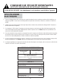
3. This 115V air conditioner uses 6.5 or less nameplate amps and may be used in any properly wired, general-purpose
household receptacle. See Table 1 for the specifi cations for the individual branch circuit.
4. For your safety and protection, this unit is grounded through the powercord plug when plugged into a matching wall
outlet. If you are not sure whether your wall outlet is properly grounded, please consult a qualifi ed electrician.
5. The wall outlet must match the 3-prong plug on the service cord supplied with the unit. DO NOT use plug adapters.
See Table 2 for receptacle and fuse information.
6. The rating plate on the unit contains electrical and other technical data. The rating plate is located on the right side of
the unit, above the powercord.
ELECTRICAL
REQUIREMENTS
TABLE 1 DAC080BAUWDB
Suggested Individual Branch Circuit
Nameplate Amps
6.5
*AWG Wire Size
16
AWG- American Wire Gauge
*Based on copper wire at 60°C temperature rating
TABLE 2
Receptacle and Fuse Types
Rated Volts 125
Amps 15
Wall Outlet
Fuse Size 15
Time Delay Fuse Plug Type
(or Circuit Breaker)

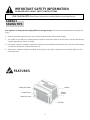
FEATURES
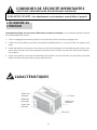
Your appliance is designed to be highly effi cient in energy savings. Follow these recommendations for greater effi -
ciency.
1. Select a thermostat setting that suits your comfort needs and leave at that chosen setting.
2. The air fi lter is very effi cient in removing airborne particles. Keep the air fi lter clean at all times. (Usually cleaned every
2 weeks depending on indoor air quality.)
3. Use drapes, curtains or shades to keep direct sunlight from penetrating and heating the room, but do not allow drapes
or curtains to obstruct the air fl ow around the unit.
4. Start your air conditioner before the outdoor air becomes hot, to avoid an initial period of discomfort while the unit is
cooling the room.
IMPORTANT SAFETY INFORMATION
READ AND FOLLOW ALL SAFETY INSTRUCTIONS
FOR YOUR SAFETY: Read these instructions carefully before operating the unit.
ENERGY
SAVING TIPS
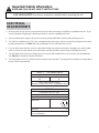
Air Filter
Cabinet
Air Filter
Exterior
Air Inlet
Interior Air Inlet
Control Panel
Interior Air Outlet
3

INSTALLATION INSTRUCTIONS
TOOLS NEEDED FOR INSTALLATION:
• Screwdrivers: Phillips and fl at head.
• Power Drill: 1/8” (3.2mm) diameter drill bit
• Pencil
• Measuring Tape
• Scissors
• Carpenter’s Level
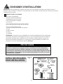
NOTE: Save the shipping carton and packing materials for future storage or transportation. From
the carton, remove the plastic bag containing the installation hardware kit necessary for the in-
stallation of your air conditioner. Please check the contents of the hardware kit against the corre-
sponding model check list, prior to installation of the unit. See Fig. 1.
ELECTRIC SHOCK HAZARD
To avoid the possibility of personal
injury, disconnect power to the unit
before installing or servicing.
NOTE: Your Room Air Conditioner is designed for easy installation in a single or double-hung window. This unit is NOT
designed for vertical (slider type) windows and/or through-the-wall applications.
Because the compressor is located on the controls side of the unit (left side), this side
will be heavier and more awkward to manipulate. Inadequate support on control side of
the unit can result in personal injury and damage to your unit and property. Therefore, it
is recommended that you have someone assist you during the installation of this unit.
CAUTION
1/2in. (13 mm)
screws (7)
Safety Lock (1)
3/8in. (9.5mm) screws
(4) *Factory installed
on some models
“L” Shaped
mounting
bracket (1)
* Factory installed
on some models
Sash bracket (2)
Adhesive
Foam Seal(1)
Side Curtain LH (1)
Side Curtain RH (1)
Regular
Foam Seal(1)
Foam insert
2 pieces
Weather-stripping
(5)
Fig. 1
4
INSTALLATION
HARDWARE

1. This room air conditioner is designed to fi t easily into a single or double hung window. However, since window designs
vary, it may be necessary to make some modifi cations for safe, proper installation.
2. Make sure window and frame are structurally sound and free from dry and rotted wood.
3. For maximum effi ciency, install the air conditioner on a side of the house or building which favours more shade than
sunlight. If the unit is in direct sunlight, it is advisable to provide an awning over the unit.
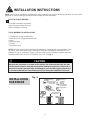
4. Provide suffi cient clearance around the cabinet to allow for ample air circulation through the unit (See Fig. 2). The
rear of the unit should be outdoors. It should not be in a garage, or inside a building. Keep unit as far away as possi-
ble from obstacles/obstructions and at least 30” above the fl oor or ground. Curtains and other objects within the room
should be prevented from blocking the air fl ow.
5. Be certain that the proper electrical outlet is within reach of the installation. Use only a single outlet circuit rated at 15
amps. All wiring should be in accordance with local and national electrical codes.
6. DO NOT install unit where leakage of combustible gas is suspected. Your air conditioner may fail to operate in air
containing oils (including machine oils), sulfi de gas, near hot springs, etc.
NOTE: Your unit is designed to evaporate condensation under normal conditions. However, under extreme humidity con-
ditions, excess condensation may cause basepan to overfl ow to the outside. The unit should be installed where conden-
sation run-off cannot drip on pedestrians or neighbouring properties.
NOTE: It is normal for your unit to drip a small amount of water, especially on excessively humid days.
5
INSTALLATION INSTRUCTIONS
Awning
Fence,
wall, or
other
obstacle
Ground
Side
Obstruction
20 in.
(50.8 cm)
Min
30 in. (76.2 cm)
Min
Min
12 in. (30.5 cm) Min
20 in.
(50.8 cm)
Fig. 2
LOCATION

6
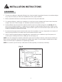
1. Assembly of the upper channel to the cabinet (factory installed on some units).
• “L” Shaped Top Channel: install the “L” shaped channel to the top of the cabinet as shown in Fig. 3, using four (4) 3/8”
screws.
2. Assembly of the side curtains to the cabinet.
• Extend the shutter from the shutter frame and slide it into the shutter tabs on the side channel of the air conditioner,
as shown in Fig. 4.
• Slide the shutters into the top (“L” shaped) and bottom (“U” shaped) channels. The shutters are identifi ed (on frame)
as left and right.
3/8” screws
“L” shaped mounting
bracket
“U” shaped Channel
(Factory Installed)
Fig. 3
Slide down into tabs
Shutter tabs
Shutter
Shutter frame
Fig. 4
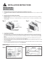
3. Completing the installation.
• Carefully place the air conditioner into the window with the “L” shaped mounting bracket (on top) positioned in front
of the upper window sash. The bottom of the cabinet should be positioned on the “recessed” portion of the window
frame. Pull the window down until it rests just behind the front fl ange of the (top) “L” shaped mounting bracket (See
Fig. 5).
• Expand the shutter frames (fully) on each side and secure the top of the frames to the window sash using one 1/2”
screw on each side and one in the “L” shaped mounting bracket (Fig. 5).
• Secure the shutter clamp on each side of the lower part of the shutter, and secure to window sill using one 1/2” screw
on each side (Fig. 5).
• Place the second foam sealing strip to fi t the opening between the inside and outside windows, then attach the safety
lock to the outside window frame using one 1/2” screw (See Fig. 6).
PLEASE NOTE: Window applications come in a variety of different styles. Therefore, it may be necessary to modify your
particular installation.
Window sash
“L” Shaped
Mounting
Bracket
Shutter clamps
1/2” screws
Safety Lock
1/2” screw
Foam Seal
Fig. 6Fig. 5
INSTALLATION
INSTRUCTIONS
INSTALLATION INSTRUCTIONS

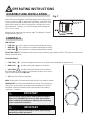
OPERATING INSTRUCTIONS
Turn the selector switch slowly, allowing the unit to adjust.
When using THERMOSTAT, be sure to allow three minutes
before changing the temperature. Adjusting too quickly may
cause compressor to overload.
IMPORTANT
7
Check that the air conditioner is tilted downwards to the outside, about
3° to 4°, as shown in Fig. 7. After proper installation, condensed water
should not drain from the overfl ow drain hole during normal use. If you
notice water leaking out, check the angle of tilt, and make any neces-
sary adjustments. However, on a very humid day, water leakage can
occur – this is normal.
Measure the tilt angle from the cabinet’s edge. The distance H should
be approximately 3/4” to 1”.
Measure the tilt angle from the cabinet’s edge
WINDOW
: approximately
5/8” to 3/4”
Fig. 7
FAN SPEEDS:
• LOW FAN will circulate air at minimum speed without cooling.
• MED FAN will circulate air at a medium speed without cooling.
• HIGH FAN will circulate air at maximum speed without cooling.
SELECTOR SWITCH: The selector switch controls cooling mode. Simply rotate the SELECTOR knob to one of the two
settings described below.
COOLING MODES:
• LOW COOL provides cooling with minimum air circulation. Recommended for night-time use.
• MED COOL provides cooling with medium air circulation.
• HIGH COOL provides cooling with maximum air circulation.
Recommended for quick cooling or for extremely hot days. Once room is
cooled, reduce setting to LOW COOL.
• OFF shuts the unit down completely.
NOTE: Always allow 3 minutes before switching from one mode to another.
THERMOSTAT: The thermostat automatically controls the (compressor)
cooling cycle and maintains the selected room temperature. To set the
thermostat, rotate the thermostat knob to the desired cooling setting
(1 warmest - 7 coldest).
3/4” to 1”
1
O
Arrêt
7
2
3
4
5
6
ASSEMBLY AND INSTALLATION
CONTROLS
Control panel may not be exactly as shown. Panel can vary
depending on model purchased.
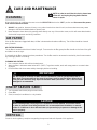
IMPORTANT

When cleaning the air conditioner be sure to turn the SELECTOR knob to the “OFF” position and disconnect the power
cord from the electrical outlet.
1. DO NOT use gasoline, benzene, thinner, or any other chemicals to clean this unit, as these substances may cause
damage to the fi nish and deformation of plastic parts.
2. Never attempt to clean the unit by pouring water directly over any of the surface areas, as this will cause deterioration
of electrical components and wiring insulation.
If the air fi lter becomes clogged with dust, air fl ow is obstructed and reduces effi ciency. The air fi lter should be cleaned
every 2 weeks.
AIR FILTER REMOVAL:
The air fi lter is located behind the air intake front grill. To remove the air fi lter, grasp the fi lter handle on the front of the grill
and slide it out to the right.
To reinstall the air fi lter, reverse the above procedures. The air fi lter must be vacuumed or washed by hand in warm water.
Dry thoroughly before re-installing.
CLEANING AIR FILTER:
1. Use a vacuum cleaner with soft brush attachment.
2. Wash the fi lter in lukewarm water below 40°C (104°F). To get best results, wash with soapy water or a neutral clean-
ing agent.
3. Rinse the fi lter with clean water and dry thoroughly before re-installing.
1. Turn off power and remove plug from wall socket.
2. Clean fi lter.
3. Store (covered) air conditioner in a dry location.
CLEANING
END OF SEASON CARE
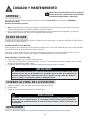
CARE AND MAINTENANCE
IMPORTANT
DO NOT forget to install the air fi lter. If the air conditioner is left to operate without the air
fi lter, dust is not removed from the room air and may result in machine failure. When the air
inlet grill and cabinet are dirty, wipe with lukewarm water (below 40°C / 104°F). Use of a mild
detergent is recommended.
CAUTION
When installing and/or removing the air conditioner from the window, ensure that caution
is taken to prevent it from falling backward. It is recommended that installation or removal
of the air conditioner is done with assistance, to prevent injury to persons or damage to the
unit or property.
DISPOSAL
Check for local regulatory compliance regarding the approved and safe disposal of this appliance.
NOTE: In order to avoid electric shock, please turn
off the A/C and unplug the plug before mainte-
nance or repair.
8
AIR FILTER

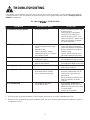
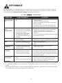
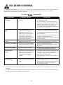
TROUBLESHOOTING
9
PROBLEM POSSIBLE CAUSE SOLUTION
Air conditioner will not operate • No power to the unit • Check connection of power cord
to power source.
• Check fuse or circuit breaker.
• Set SELECTOR SWITCH to
position other than “OFF”. The
power cord “RESET” button must
always be pushed in (engaged)
for correct operation.
Ineffi cient or no cooling • Dirty air fi lter
• Unit size inappropriate for appli-
cation
• Blocked air fl ow
• Power interruption, settings
changed too quickly, or compres-
sor overload tripped
• Clean/replace air fi lter
• Check with dealer to determine
proper unit capacity for application
• Remove obstruction from grill or
outdoor louvres
• Turn the unit off and wait 5 min-
utes before attempting to restart
Noisy unit • Loose parts
• Inadequate support
• Tighten loose parts
• Provide additional support to unit
Odors • Formation of mold, mildew, or
algae on wet surfaces
• Clean unit thoroughly
• Place algaecide tablet in base pan
Water dripping outside • Hot and humid weather • Condensation run-off is normal
under these conditions.
Water dripping inside • Unit is not properly angled to
allow water to drain outside
• It is an extremely humid day
• Unit must be installed on an angle
for proper condensation run-off.
Check the unit and make any
adjustments.
• On an extremely humid day, this
effect is expected. No action
required.
Ice or frost build-up • Low outside temperature
• Unit air fi lter is dirty
• When outdoor temperature is
approximately 18.3°C (65°F) or
below, frost may form when unit is
in cooling mode.
• Remove and clean fi lter
NOTES:
1. If circuit breaker is tripped repeatedly, or fuse is blown more than once, contact a qualifi ed technician.
2. When the unit is installed using proper installation steps, the unit is properly tipped toward the outdoors to allow for
condensation run-off.
Occasionally, a minor problem may arise, and a service call may not be necessary- use this troubleshooting guide for
a possible solution. If the unit continues to operate improperly, call an authorized service depot or Danby’s Toll Free
Number for assistance.
Tel: 1-800-26- (1-800-263-2629)

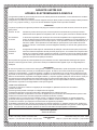
LIMITED IN-HOME APPLIANCE WARRANTY
This quality product is warranted to be free from manufacturer’s defects in material and workmanship, provided that the unit is used under the normal operating
conditions intended by the manufacturer.
This warranty is available only to the person to whom the unit was originally sold by Danby Products Limited (Canada) or Danby Products Inc. (U.S.A.) (hereafter
“Danby”) or by an authorized distributor of Danby, and is non-transferable.
TERMS OF WARRANTY
Plastic parts, are warranted for thirty (30) days only from purchase date, with no extensions provided.
First Year
During the rst twelve (12) months, any functional parts of this product found to be defective, will be repaired or replaced, at warrantor’s
option, at no charge to the ORIGINAL purchaser.
To obtain
Danby reserves the right to limit the boundaries of “In Home Service” to the proximity of an Authorized Service Depot. Any app liance
Service
requiring service outside the limited boundaries of “In Home Service” , it will be the consumer’s responsibility to transport the appliance (at
their own expense) to the original retailer (point of purchase) or a service depot for repair. See “Boundaries of In Home Serv ice” below.
Contact your dealer from whom your unit was purchased, or contact your nearest authorized Danby service depot, where service
must be performed by a qualied service technician.
If service is performed on the units by anyone other than an authorized service depot, or the unit is used for commercial appli cation, all
obligations of Danby under this warranty shall be void.
Boundaries of
If the appliance is installed in a location that is 100 kilometers (62 miles) or more from the nearest service center your unit must be
In Home Service
delivered to the nearest authorized Danby Service Depot, as service must only be performed by a technician qualied and certif ied for
warranty service by Danby. Transportation charges to and from the service location are not protected by this warranty and are t he
responsibility of the purchaser.
Nothing within this warranty shall imply that Danby will be responsible or liable for any spoilage or damage to food or other c ontents of this appliance, whether due
to any defect of the appliance, or its use, whether proper or improper.
EXCLUSIONS
Save as herein provided, Danby, there are no other warranties, conditions, representations or guarantees, express or implied, m ade or intended by Danby or its
authorized distributors and all other warranties, conditions, representations or guarantees, including any warranties, conditio ns, representations or guarantees
under any Sale of Goods Act or like legislation or statue is hereby expressly excluded. Save as herein provided, Danby shall no t be responsible for any damages
to persons or property, including the unit itself, howsoever caused or any consequential damages arising from the malfunction o f the unit and by the purchase of
the unit, the purchaser does hereby agree to indemnify and hold harmless Danby from any claim for damages to persons or propert y caused by the unit.
GENERAL PROVISIONS
No warranty or insurance herein contained or set out shall apply when damage or repair is caused by any of the following:
1) Power failure.
2) Damage in transit or when moving the appliance.
3) Improper power supply such as low voltage, defective house wiring or inadequate fuses.
4) Accident, alteration, abuse or misuse of the appliance such as inadequate air circulation in the room or abnormal operating con ditions
(extremely high or low room temperature).
5) Use for commercial or industrial purposes (ie. If the appliance is not installed in a domestic residence).
6) Fire, water damage, theft, war, riot, hostility, acts of God such as hurricanes, oods etc.
7) Service calls resulting in customer education.
8) Improper Installation (ie. Building-in of a free standing appliance or using an appliance outdoors that is not approved for out door application).
Proof of purchase date will be required for warranty claims; so, please retain bills of sale. In the event warranty service is required, present this document to our
AUTHORIZED SERVICE DEPOT.
Danby Products Limited
PO Box 1778, Guelph, Ontario, Canada N1H 6Z9
Telephone: (519) 837-0920 FAX: (519) 837-0449
Danby Products Inc.
PO Box 669, Findlay, Ohio, U.S.A. 45840
Telephone: (419) 425-8627 FAX: (419) 425-8629
04/09
1-800-263-2629
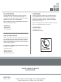
Warranty Service
In-home
If the appliance is installed in a location that is 100 kilometres (62 miles) or more from the nearest
service centre your unit must be delivered to the nearest authorized Danby Service Depot, as service
must only be performed by a technician qualified and certified for warranty service by Danby. Transpor-
tation charges to and from the service location are not protected by this warranty and are the responsi-
bility of the purchaser.
During the first twelve (12) months, any functional parts of this product found to be defective, will be
repaired or replaced, at warrantor’s option, at no charge to the ORIGINAL purchaser.
Danby reserves the right to limit the boundaries of “In Home Service” to the proximity of an Authorized
Service Depot. Any appliance requiring service outside the limited boundaries of “In Home Service” ,it
will be the consumer’s responsibility to transport the appliance (at their own expense) to the original
retailer (point of purchase) or a service depot for repair. See “Boundaries of In Home Service” below.
Contact your dealer from whom your unit was purchased, or contact your nearest authorized Danby
service depot, where service must be performed by a qualified service technician. If service is performed
on the units by anyone other than an authorized service depot, or the unit is used for commercial
application, all obligations of Danby under this warranty shall be void.
First year
To obtain
service
Boundaries of
in-home service
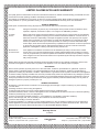
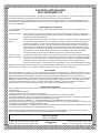
LIMITED IN-HOME APPLIANCE WARRANTY
This quality product is warranted to be free from manufacturer’s defects in material and workmanship, provided that the unit is
used under the normal operating conditions intended by the manufacturer.
This warranty is available only to the person to whom the unit was originally sold by Danby Products Limited (Canada) or
Danby Products Inc. (U.S.A.) (hereafter “Danby”) or by an authorized distributor of Danby, and is non-transferable.
TERMS OF WARRANTY
Plastic parts, are warranted for thirty (30) days only from purchase date, with no extensions provided.
Nothing within this warranty shall imply that Danby will be responsible or liable for any spoilage or damage to food or other
contents of this appliance, whether due to any defect of the appliance, or its use, whether proper or improper.
EXCLUSIONS
Save as herein provided, by Danby, there are no other warranties, conditions, representations or guarantees, express or
implied, made or intended by Danby or its authorized distributors and all other warranties, conditions, representations or
guarantees, including any warranties, conditions, representations or guarantees under any Sale of Goods Act or like legislation
or statute is hereby expressly excluded. Save as herein provided, Danby shall not be responsible for any damages to persons
or property, including the unit itself, howsoever caused or any consequential damages arising from the malfunction of the unit
and by the purchase of the unit, the purchaser does hereby agree to indemnify and hold harmless Danby from any claim for
damages to persons or property caused by the unit.
GENERAL PROVISIONS
No warranty or insurance herein contained or set out shall apply when damage or repair is caused by any of the following:
1) Power failure.
2) Damage in transit or when moving the appliance.
3) Improper power supply such as low voltage, defective house wiring or inadequate fuses.
4) Accident, alteration, abuse or misuse of the appliance such as inadequate air circulation in the room or abnormal operating
conditions (extremely high or low room temperature).
5) Use for commercial or industrial purposes (i.e., If the appliance is not installed in a domestic residence).
6) Fire, water damage, theft, war, riot, hostility, acts of God such as hurricanes, floods etc.
7) Service calls resulting in customer education.
8) Improper Installation (i.e., building-in of a free standing appliance or using an appliance outdoors that is not approved for
outdoor application). Proof of purchase date will be required for warranty claims; so, please retain bills of sale. In the event
warranty service is required, present this document to our AUTHORIZED SERVICE DEPOT.
Warranty Service
In-home
Danby Products Limited
PO Box 1778, Guelph, Ontario, Canada N1H 6Z9
Telephone: (519) 837-0920 FAX: (519) 837-0449
Danby Products Inc.
PO Box 669, Findlay, Ohio, U.S.A. 45840
Telephone: (419) 425-8627 FAX: (419) 425-8629
1-800-263-2629
07/14

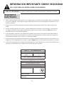
BIENVENUE
11
Bienvenue dans la famille Danby. Nous sommes fi ers de la qualité de nos produits et nous croyons fermement au service
par une assistance fi able. Vous découvrirez au travers de ce quide, facile d’utilisation et vous en aurez la confi rmation par
notre service d’assistance à la clientèle. Mais ce qui est encore mieux, vous pourrez bénéfi cier de ces valeurs à chaque
utilisation de votre appareil. Ceci est important parce que votre nouvel appareil fera partie de votre famille pour long-
temps.
À titre de référence, vous pouvez agrafer à cette page une copie de votre fi che d’achat de l’appareil. Inscrivez les rensei-
gnements suivants fournis (sur la plaque signalétique du fabricant sur le côté droit de l’appareil au-dessus du cordon
d’alimentation). Vous aurez besoin de ces renseignements si vous contactez un représentant du service à la clientèle.
S’il vous plaît écrivez informations ci-dessous; ces renseignements seront nécessaires si votre appareil a besoin
d’entretien ou pour les demandes de renseignements généraux. Pour bénéfi cier d’une opération de maintenance
ou dépannage, le reçu original sera exigé.
REMARQUE : CET APPAREIL N’A PAS ÉTÉ CONÇU POUR UNE INSTALLATION À TRAVERS UNE PAROI.
Numéro de modèle :
Numéro de série :
Date d’achat :
BESOIN D’ASSISTANCE ?
Veuillez trouver quelques conseils avant de faire appel à nos
services, cela nous aidera à mieux vous servir :
Lisez ce guide :
Il comprend des instructions pour l’utilisation et l’entretien
adapté de votre unité.
Si votre nouvel appareil est endommagé :
Contactez immédiatement le revendeur (ou le fabricant).
Gagnez du temps et de l’argent :
Avant de faire appel à nos services, consultez à nouveau
la section « “Dépannage ». Cette section vous aidera à
solutionner des problèmes courants.
Si une réparation est nécessaire, ne vous inquiétez pas, la
solution est au bout de l’appel téléphonique.
AVERTISSEMENT :
Une fi che de mise à la terre mal branchée peut entraîner un risque d’incendie, de
choc électrique ou de blessures aux personnes qui utilisent l’appareil. Si vous
n’êtes pas certain que l’appareil est correctement mis à la terre, consultez un
préposé du service qualifi é.
1-800-26-
(1-800-263-2629)

12
CONSIGNES DE SÉCURITÉ IMPORTANTES
LISEZ TOUTE L’INFORMATION DE SÉCURITÉ AVANT UTILISATION
POUR VOTRE SÉCURITÉ : Lire attentivement ces instructions avant d’utiliser l’appareil.
1. Tous les câblages doivent être conformes aux codes électriques locaux et nationaux et doivent être installés par un
électricien qualifi é. Si vous avez la moindre question au suject des instructions ci-dessous, contactez un électricien
qualifi é.
2. Vérifi ez la fourniture d’alimentation électrique disponsible et résolvez tout problème de câblage AVANT d’installer et
de faire fonctionner cet appareil.
3. Ce climatiseur à 115V utilise 6,5 ampères ou moins de puissance nominale et peut être utilisé dans toute prise de
courant domestique de but général adéquatement câblée. Reportez-vous au Tableau 1 pour les spécifi cations con-
cernant le circuit de dérivation individuel.
4. Pour votre sécurité et votre protection, cet appareil est mis à la masse par la fi che du cordon d’alimentation lorsqu’elle
est branchée dans une prise murale qui lui correspond. Si vous n’êtes pas certain que votre prise de courant murale
est mise à la masse adéquatement, veuillez consulter un électricien qualifi é.
5. La prise murale doit correspondre à la fi che à 3 broches sur le cordon de service fourni avec l’appareil. N’utilisez PAS
de fi ches d’adaptation. Voir Tableau 2 pour les renseignements sur les prises de courant et les fusibles.
6. La plaque signalétique sur l’appareil contient des données électriques et techniques; elle se trouve sur le côté droit de
l’appareil, au-dessus du cordon d’alimentation.
SPECIFICATIONS
ELECTRIQUES
TABLEAU 1 DAC080BAUWDB
Circuit de distribution individuel suggéré
Ampères de plaque
d’identifi cation
6,5
Calibre de fi l AWG*
16
AWG – American Wire Gauge
(Calibre de fi l américain)
*Basé sur le fi l en cuivre à une température nominale
de 60°C
TABLEAU 2
Types de fusibles et de réceptacles
Tension nominale 125
Ampères 15
Prise de courant
Intensité de fusible 15
Fusible temporisé Type fi che
(ou disjoncteur de circuit)

CARACTÉRISTIQUES
L’ÉCONOMIE DE
L’ÉNERGIE
Air FilterFiltre à air
Entrée d’air
extérieure
Entrée d’air
intérieure
Tableau de
commande
Sortie d’air
intérieure
Caisson
13
Votre appareil ménager est conçu pour l’effi cacité en économie de l’énergie. Pour le rendement maximal, observer
les recommandations qui suivent.
1. Choisir un réglage du thermostat qui répond à vos besoins de confort et le laisser au réglage choisi.
2. Le fi ltre à air est très effi cace pour éliminer les particules qui fl ottent dans l’air. Conserver le fi ltre à air propre en tout
temps.
3. Utiliser des draperies, des rideaux ou des stores pour prévenir la pénétration et le réchauffement de la pièce par les
rayons directs du soleil, mais ne pas permettre la restriction de la circulation d’air autour de l’unité par les draperies
ou les rideaux.
4. Activer votre climatiseur avant que la température de l’air extérieur ne soit très chaude. Ceci préviendra une période
initiale d’inconfort avant que l’unité ne puisse refroidir la pièce.
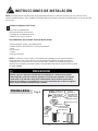
CONSIGNES DE SÉCURITÉ IMPORTANTES
LISEZ TOUTE L’INFORMATION DE SÉCURITÉ AVANT UTILISATION
POUR VOTRE SÉCURITÉ : Lire attentivement ces instructions avant d’utiliser l’appareil.

CONSIGNES D’INSTALLATION
OUTILS NÉCESSAIRES POUR INSTALLATION :
• Tournevis à tête Phillips et plate
• Perceuse électrique Mèche de 1/8 po de diam.
• Crayon
• Ruban à mesure
• Ciseaux
• Clé réglable
REMARQUE : Conservez le carton d’expédition et le matériel d’emballage pour futur entreposage
ou transport de l’appareil. Ôtez l’appareil du carton, le sac en plastique qui contient la trousse de
quincaillerie nécessaire pour l’installation de votre climatiseur. Veuillez vérifi er le contenu de la
trousse de quincaillerie d’installation en le comparant à la liste de vérifi cation du modèle corre-
spondant, et ce, avant l’installation de l’appareil. Voir Fig. 1.
RISQUE DE CHOC ÉLECTRIQUE
Pour éviter la possibilité de
blessures corporelles, débrancher
l’alimentation de courant à l’unité
avant d’entreprendre l’installation
ou le service.
Comme le compresseur se trouve du côté des commandes de l’unité (côté gauche),
ce côté est plus lourd et plus diffi cile à manipuler. Un soutien inapproprié du côté des
commandes de l’appareil peut causer des blessures et endommager l’appareil et d’autres
biens mobiliers. C’est pourquoi il est recommandé que quelqu’un vous aide au cours de
l’installation de cet appareil.
MISE EN GARDE
Vis de 1/2po
(13mm)(7)
Serrure de
Sûreté (1)
Vis de 3/8po (9.5mm)
(4) *Préinstallé sur
certain modèles
Canal supérieur
(1) *Préinstallé
sur certain
modèles
Support de
fermeture (2)
Scellement
mousse
(1)
adhésif
Rideau latéral
gauche (1)
Rideau latéral droit (1)
Scellement
mousse
régulière
(1)
Fig. 1
14
REMARQUE : Votre climatiseur de chambre a été conçu pour une installation facile dans une fenêtre à châssis à
guillotine simple ou double. Cet appareil n’a pas été conçu pour des fenêtres verticales (de type coulissant) ou pour être
installé à travers une paroi.
OUTILS NÉCESSAIRES
POUR INSTALLATION

1. Ce climatiseur pour chambre a été conçu pour être installé facilement dans une fenêtre à châssis à guillotine simple
ou double. Cependant, comme le design de la fenêtre peut varier, it peut être nécessaire d’y faire quelques modifi ca-
tions pour une installation sécuritaire et appropriée.
2. Assurez-vous que la fenêtre et son châssis sont structurellement solides et exempts de bois sec et pourri.
3. Pour un maximum d’effi cacité, installez le climatiseur sur le côté de la maison ou de l’immeuble qui se trouve plus
souvent à l’ombre qu’au soleil. Si l’appareil est directement sous les rayons du soleil, installer un auvent pour protéger
l’unité.
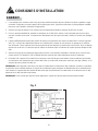
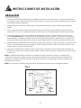
4. Laissez suffi samment d’espace libre autour du caisson pour permettre une ample circulation d’air à travers l’appareil.
Voir Fig. 2. L’arrière de l’appareil doit donner sur l’extérieur de la maison et non pas dans un garage ou à l’intérieur
d’un immeuble. Tenez l’appareil aussi loin que possible de tout obstacle ou obstruction et à au moins 30 po au-dessus
du plancher ou du sol. Il ne faut pas que les rideaux ou d’autres objets à l’intérieur de la pièce puissent bloquer le fl ux
d’air.
5. Assurez-vous que la prise électrique appropriée se trouve à la portée de l’installation. N’utilisez qu’un circuit à prise
unique calculé à 15 ampères. Tout le câblage doit être conforme aux codes électriques locaux et nationaux.
6. N’insallez PAS l’appareil à un endroit où on soupçonne une fuite de gaz combustibles. Votre climatiseur peut tomber
en panne dans une atmosphère qui contient des huiles (y compris des huiles pour machines), des gaz sulfurés, ou s’il
est près de sources d’eau chaude, etc.
REMARQUE : Votre appareil a été conçu pour que la condensation s’évapore dans des conditions normales. Cependant,
en présence d’une humidité extrême, un surplus de condensation peut provoquer un débordement de la cuvette de base
vers l’exterieur. L’appareil doit être installé de telle sorte que l’écoulement de la condensation ne se déverse pas sur des
passants ou sur des proriètés avoisinantes.
REMARQUE : Il est normal que l’appareil coule légèrement, surtout lors des journées excessivement humides.
15
CONSIGNES D’INSTALLATION
Auvent
Clôture,
mur ou
autre
obstacle
Sol
Obstacle
latéral
20 po
(50,8
cm)
min.
30 po (76 cm)
min.
20 po (50,8 cm)
12 po (30,5 cm) min.
min.
Fig. 2
ENDROIT

16
CONSIGNES D’INSTALLATION
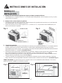
1. Montage de canaux supérieur sur le caisson (préinstallé sur certain modèles).
• Canal supérieur en forme de “L”: Installez le canal en forme de “L” au-dessus du caisson tel que montré à la Fig. 3,
un utilisant quatre (4) vis de 3/8 po.
2. Montage des rideaux latéraux au caisson.
• Étendez les volets et glissez-le dans les support de volets sur le canal latéral du climatiseur comme montré dans Fig.
4.
• Faites glisser les cadre des volets dans les canaux supérieur (en formede “L”) et inférieur (en forme de “U”) Ces vo-
lets sont identifi és (sur le cadre) en tant que volets gauches et droits.
Vis de 3/8 po
Canal en form de
“L”
Canal en forme de “U”
Fig. 3
Glissez
vers le bas
Support
Volets
Cadre des volets
de volets
Fig. 4
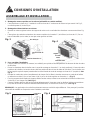
3. Pour compléter l’installation
• Coupez la lisière à calfeutrer en mousse (non adhésif) pour qu’elle se fi xe adéquatement au dessous du bas du cadre
de la fenêtre.
• Placez le climatiseur dans la fenêtre avec le canal de montage en forme de “L” (en haut) positionné à l’avant du cadre
supérieur de la fenêtre. Le bas du caisson doit être positionné dans le bas du cadre de la fenêtre. Tirez la fenêtre vers
le bas jusqu’à ce qu’elle repose juste derrière le rebord frontal du canal de montage en forme de “L” (supérieur). Voir
Fig. 5.
• Étendez les cadres des volets (complètement) de chaque côté, et fi xez le haut des structures au cadre de la fenêtre
en utilisant une vis de 1/2 po, et une autre vis de ½ po sur le canal supérieur en forme de « L » (Fig. 5).
• Fixez les supports de fermeture de chaque côté du bas des volets, et fi xez-lez au rebord de la fenêtre en utilisant une
vis de 1/2 po, sur chaque côté (Voir Fig. 6).
• Coupez la bande adhésive afi n qu’elle s’ajuste adéquatement à l’ouverture entre les fenêtres intérieure et extérieure.
Puis, fi xez la serrure de sureté au cadre de fenêtre extérieure, en utilisant une vis de 1/2 po (Voir Fig. 6).
REMARQUE : Les applications à une fenêtre présentent toute une variété de styles différents. C’est pourquoi il peut être
nécessaire de modifi er ou d’improviser votre installation particulière.
Cadre de la
fenêtre
Canal supérieur
en forme de “L”
Support de fermeture
Vis de 1/2 po
Serrure de sûreté
Vis de 1/2 po
Scellement
mousse
(adhésif)
Fig. 6Fig. 5
ASSEMBLAGE ET INSTALLATION

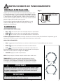
CONSIGNES D’UTILISATION
Tournez le commutateur de sélection lentement pour que le climatiseur se
règle bien. Quand vous utilisez le THERMOSTAT, assurez-vous d’attendre
trois minutes avant de passer d’une température à une autre. En le réglant
trop rapidement, on peut provoquer une surcharge du compresseur.
IMPORTANTE
17
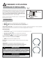
Mesurez l’angle d’inclination du bord du caisson.
FENÊTRE
EXTÉRIEUR
INTÉRIEUR
: environ
5/8 po à 3/4 po
Vérifi ez que le climatiseur est incliné vers le bas à l’extérieur, environ 3°
à 4°, selon Fig. 7. Après une installation adéquate, l’eau condensée ne
devrait pas s’écouler du trou de drainage pendant une utilisation nor-
male. Si vous remarquez d’égouttement d’eau, vérifi ez l’angle d’incli-
nation et exécutez tout ajustement. Pourtant, lorsqu’il fait très humide,
l’égouttement d’eau peut arriver – cela est normale.
Mesurez l’angle d’inclination du bord du caisson. L’intervalle H devrait
être environ 3/4 à 1 pouces.
Fig. 7
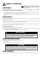
VITESSE DU VENTILATEUR :
• BAS l’air circule à une vitesse minimum, sans refroidissement.
• MOYENNE l’air circule à une vitesse moyenne, sans refroidissement.
• HAUT l’air circule à une vitesse maximum, sans refroidissement.
FONCTION DE SÉLECTION : Le commutateur de sélection commande le mode du refroidissement. Tournez simplement
le bouton du SÉLECTEUR pour le positionner sur l’un des deux réglages décrits ci-dessous.
REFROIDISSEMENT :
• BAS REFROIDIT avec un min. de circulation d’air. Recommandé pour la nuit.
• MOYENNE REFROIDIT avec un moyenne de circulation d’air.
• HAUT REFROIDIT avec une circulation d’air max. Recommandé
pour un refroidissement rapide ou en temps de canicules. Une fois la pièce
refroidie, il faut réduire le refroidissement à FAIBLE.
• ARRÊT cette fonction éteint complètement l’unité.
REMARQUE : Il faut toujours attendre 3 minutes avant de passer d’un réglage
à un autre.
THERMOSTAT : Le thermostat contrôle complètement le cycle de
refroidissement (compresseur) et maintient la température choisie pour la
chambre. Pour régler le thermostat, tournez le bouton du thermostat au
reglage de refroidissement désiré (1 le plus chaud - 7 le plus froid).
3/4 po à 1 po
1
O
Arrêt
7
2
3
4
5
6
ASSEMBLAGE ET INSTALLATION
COMMANDES
Le panneau de contrôle peaut paraître différemment qu’indiqué.
Le panneau peut varier selon le modèle acheté.
IMPORTANTE
La page est en cours de chargement...
La page est en cours de chargement...
La page est en cours de chargement...
La page est en cours de chargement...
La page est en cours de chargement...
La page est en cours de chargement...
La page est en cours de chargement...
La page est en cours de chargement...
La page est en cours de chargement...
La page est en cours de chargement...
La page est en cours de chargement...
La page est en cours de chargement...
La page est en cours de chargement...
La page est en cours de chargement...
La page est en cours de chargement...
La page est en cours de chargement...
-
 1
1
-
 2
2
-
 3
3
-
 4
4
-
 5
5
-
 6
6
-
 7
7
-
 8
8
-
 9
9
-
 10
10
-
 11
11
-
 12
12
-
 13
13
-
 14
14
-
 15
15
-
 16
16
-
 17
17
-
 18
18
-
 19
19
-
 20
20
-
 21
21
-
 22
22
-
 23
23
-
 24
24
-
 25
25
-
 26
26
-
 27
27
-
 28
28
-
 29
29
-
 30
30
-
 31
31
-
 32
32
-
 33
33
-
 34
34
-
 35
35
-
 36
36


Danby DAC080BAUWDB Le manuel du propriétaire
- Catégorie
- Climatiseurs split-system
- Taper
- Le manuel du propriétaire