Sauder Storage Organizer 422647 Mode d'emploi
- Taper
- Mode d'emploi

sauder.com
Storage Organizer
Model 422647
NOTE: THIS INSTRUCTION
BOOKLET CONTAINS IMPORTANT
SAFETY INFORMATION.
PLEASE READ AND KEEP FOR
FUTURE REFERENCE.
English pg 1-18
Français pg 19-21
Español pg 22-24
Lot # 531686 07/17/19
Purchased: __________________
sauder.com
CONTACT US FIRST
BEFORE MAKING ANY RETURNS TO THE STORE.
Share your journey!
sauder.com
CONTACT US FIRST
BEFORE MAKING ANY RETURNS TO THE STORE.
Visit sauder.com/service to order replacement parts, view video assembly tips, or chat with a live rep.
Prefer the phone? Give us a ring at
1-800-445-1527.
Customer Service is available Monday-Friday - 9 a.m. to 5:30 p.m. EST (except holidays)
You'll love what we
have in storage.

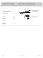
Part Identifi cation
Hardware Identifi cation
Assembly Steps
Français
Español
Safety
Warranty
No. 2 Phillips Screwdriver
Tip Shown Actual Size
Table of Contents Assembly Tools Required
Skip the power trip.
This time.
3
4
5-18
19-21
22-24
25-26
27
Page 2 www.sauder.com 422647

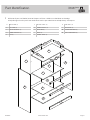
å While not all parts are labeled, some of the parts will have a label or an inked letter on the edge
to help distinguish similar parts from each other. Use this part identifi cation to help identify similar parts.
Part Identifi cation
Now you know
our ABCs.
A RIGHT END (1)
B LEFT END (1)
C UPPER UPRIGHT (1)
D LOWER UPRIGHT (1)
E TOP (1)
F UPPER SHELF (1)
G LOWER SHELF (1)
H BOTTOM (1)
I BACK (1)
J FRONT SKIRT (1)
K SIDE RAIL (2)
L BACK RAIL (1)
M FRONT MOLDING (1)
N SHELF MOLDING (2)
A
B
C
D
F
H
I
J
K
M
N
E
G
L
K
N
Page 3www.sauder.com422647

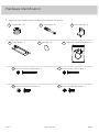
Hardware Identifi cation
å Screws are shown actual size. You may receive extra hardware with your unit.
FURNITURE TIPPING RESTRAINT KIT - 1
99
Page 4 www.sauder.com 422647
HIDDEN CAM - 20
1
CAM SCREW - 20
2
METAL BRACKET - 9
3
CARD HOLDER - 4
4
APPLIQUE - 16
5
BLACK 7/8" FLAT HEAD SCREW - 3
7
BLACK 5/16" MACHINE SCREW - 8
9
BLACK 1-3/16" FLAT HEAD SCREW - 11
6
BLACK 1/2" PAN HEAD SCREW - 43
8

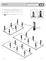
Step 1
Look for this icon. It means a
video assembly tip is available at
www.sauder.com/services/tips
å
Assemble your unit on a carpeted fl oor or on the empty
carton to avoid scratching your unit or the fl oor.
å
Turn eighteen CAM SCREWS (2) into the ENDS (A and B)
and TOP (E).
å
NOTE: Be sure to use the exact holes shown in the TOP.
Page 5www.sauder.com422647
A
B
E
(18 used)
2

UP
UP
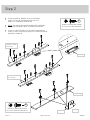
å
Fasten nine METAL BRACKETS (3) to the FRONT
SKIRT (J) and SHELF MOLDINGS (N). Use nine
BLACK 1/2" PAN HEAD SCREWS (8).
å
NOTE: The short end of the METAL BRACKET should be
fastened to the FRONT SKIRT and SHELF MOLDINGS.
å
Fasten the CARD HOLDERS (4) to the SHELF MOLDINGS (N)
exactly as shown in the enlarged diagram. Use eight BLACK 5/16"
MACHINE SCREWS (9).
Step 2
Page 6 www.sauder.com 422647
J
N
N
3
(9 used)
BLACK 1/2" PAN HEAD SCREW
(9 used for the METAL BRACKETS)
8
BLACK 5/16" MACHINE SCREW
(8 used for the CARD HOLDERS)
9
Curved edge
Short end
UP
Open end
The hole is closer
to this edge.
The hole is closer
to this edge.

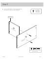
å
Fasten the UPPER SHELF (F) to the UPPER UPRIGHT (C).
Use two BLACK 1-3/16" FLAT HEAD SCREWS (6).
Step 3
Page 7www.sauder.com422647
C
F
Notched edge
Surface with holes
Surface with
more holes
BLACK 1-3/16" FLAT HEAD SCREW
(2 used in this step)
6
Remember:
Righty tighty.
Lefty loosey.

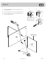
å
Turn two CAM SCREWS (2) into the exact holes shown in
the UPPER SHELF (F).
å
Push two HIDDEN CAMS (1) into the LOWER UPRIGHT (D).
å
Fasten the LOWER UPRIGHT (D) to the UPPER SHELF (F).
Tighten two HIDDEN CAMS.
Step 4
Page 8 www.sauder.com 422647
F
D
Surface with holes
Arrow
3
21
1
2
Finished edge
1
The arrow must
point toward the
edge of the board.

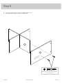
Step 5
Page 9www.sauder.com422647
D
G
å
Fasten the LOWER SHELF (G) to the LOWER UPRIGHT (D).
Use two BLACK 1-3/16" FLAT HEAD SCREWS (6).
Surface with
more holes
BLACK 1-3/16" FLAT HEAD SCREW
(2 used in this step)
6

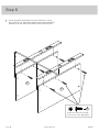
å
Fasten the SHELF MOLDINGS (N) to the SHELVES (F and G).
Use six BLACK 1/2" PAN HEAD SCREWS (8) through the METAL
BRACKETS on the SHELF MOLDINGS and into the SHELVES.
Step 6
Page 10 www.sauder.com 422647
F
G
N
N
BLACK 1/2" PAN HEAD SCREW
(6 used for the SHELF MOLDINGS)
8

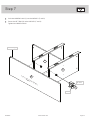
å
Push four HIDDEN CAMS (1) into the SHELVES (F and G).
å
Fasten the LEFT END (B) to the SHELVES (F and G).
Tighten four HIDDEN CAMS.
Step 7
Page 11www.sauder.com422647
F
G
B
Surface without CAM SCREWS
Notched edge
Arrow
(4 used)
1

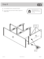
å
Push two HIDDEN CAMS (1) into the BOTTOM (H).
å
Fasten the BOTTOM (H) to the LEFT END (B). Tighten two
HIDDEN CAMS.
Step 8
Page 12 www.sauder.com 422647
Don't worry. It isn't
Rome. This can be built
in a day.
H
B
Surface with holes
These holes
must be here.
Arrow
1

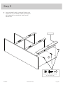
å
Fasten the FRONT SKIRT (J) to the BOTTOM (H). Use
three BLACK 1/2" PAN HEAD SCREWS (8) through the
METAL BRACKETS on the FRONT SKIRT and into
the BOTTOM.
Step 9
Page 13www.sauder.com422647
H
J
Curved edge
BLACK 1/2" PAN HEAD SCREW
(3 used in this step)
8

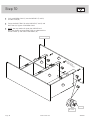
Step 10
Page 14 www.sauder.com 422647
H
G
F
A
Surface with
CAM SCREWS
Notched edge
1
Arrow
(6 used)
å
Push six HIDDEN CAMS (1) into the SHELVES (F and G)
and BOTTOM (H).
å
Fasten the RIGHT END (A) to the SHELVES (F and G) and
BOTTOM (H). Tighten six HIDDEN CAMS.
å
NOTE: You may need to lift up on the SHELVES and
BOTTOM slightly to let the RIGHT END sit underneath the
FRONT SKIRT (J) and SHELF MOLDINGS (N).
J
N
N

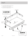
å
Fasten the FRONT MOLDING (M) to the TOP (E). Use
three BLACK 7/8" FLAT HEAD SCREWS (7).
å
Fasten the RAILS (K and L) to the TOP (E). Use seven
BLACK 1-3/16" FLAT HEAD SCREWS (6).
Step 11
Page 15www.sauder.com422647
E
K
M
L
K
Curved edge
BLACK 1-3/16" FLAT HEAD SCREW
(7 used in this step)
6
BLACK 7/8" FLAT HEAD SCREW
(3 used in this step)
7
Surface without CAM SCREWS
Finished edge
Finished edge
Unfi nished
edge

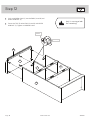
Step 12
Page 16 www.sauder.com 422647
å
Push six HIDDEN CAMS (1) into the ENDS (A and B) and
UPPER UPRIGHT (C).
å
Fasten the TOP (E) to the ENDS (A and B) and UPPER
UPRIGHT (C). Tighten six HIDDEN CAMS.
A
B
E
Hey! It's starting to look
like something!
C
Arrow
(6 used)
M
1

UP
Step 13
Page 17www.sauder.com422647
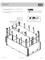
å
Carefully turn your unit over onto its front edges. Lay the
BACK (I) over your unit.
å
Fasten the BACK (I) to your unit using the BLACK 1/2" PAN
HEAD SCREWS (8).
Do not stand the unit upright without the
BACK fastened. The unit may collapse.
Caution
I
BLACK 1/2" PAN HEAD SCREW
(25 used in this step)
8
Do not use this hole.
The label
should be here.

Step 14
Page 18 www.sauder.com 422647
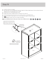
å
Carefully stand your unit upright.
å
We recommend using the FURNITURE TIPPING RESTRAINT KIT (99) for added stability. Fasten a bracket to the back
edge of the TOP (E) using the 5/8" screw as shown.
å
Place your unit in its fi nal location against a wall.
å
Follow the instructions included in the KIT to fasten your unit to the wall.
å
Peel the backing of each APPLIQUE (5) and stick them onto each visible HIDDEN CAM.
å
NOTE: Please read the back pages of the instruction booklet for important safety information.
å
This completes assembly. Clean with a damp cloth. Wipe dry.
99
Use the 5/8" screw through the
small hole in a bracket and into
the back edge of the TOP (E).
Small hole
25 lbs.
30 lbs. total
30 lbs. total
50 lbs.
5
(16 used)
To cover HIDDEN CAMS
E
And to celebrate, why not share your success story at Walmart.com or

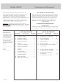
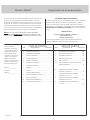
LISTE DE PIÈCES
REFERENCE DESCRIPTION QUANTITÉ
LISTE DE PIÈCES
REFERENCE DESCRIPTION QUANTITÉ
NOUS SOMMES LA POUR VOUS AIDER!
Nous faisons de notre mieux pour nous assurer que votre meuble
arrive dans d’excellentes conditions. Nos représentants du service
Clientèle sont aimables et prêts à vous aider au cas où une pièce
aurait été endommagée ou manquerait (ou si vous aviez besoin
d’aide pour l’assemblage). NE RAMENEZ PAS LE MEUBLE AU
MAGASIN. Au Canada, composez ce numéro d’appel gratuit:
1-800-445-1527
Du lundi au vendredi, de 9 heures du matin à
5:30 heures du soir (horaire Côte Est)
(sauf jours fériés)
Si une pièce a besoin d’être remplacée, la pièce de remplacement
sera envoyée dans les 48 heures. (Sauf week-ends et jours fériés)
Utilisez les instructions d’assemblage en français avec les
schémas étape par étape du manuel d’instruction en anglais.
Chaque étape en français correspond à la même étape
en anglais. La pièce devant être attachée à l’élément est
représentée en gris sur les schémas de chaque étape pour plus
de précision. Comparer la “Liste de pièces” ci-dessous avec
la “PART IDENTIFICATION” du manuel en anglais pour vous
familiariser avec les pièces avant l’assemblage.
REMARQUE : CE MANUEL D’INSTRUCTIONS CONTIENT
D’IMPORTANTES INFORMATIONS RELATIVES À LA SÉCURITÉ.
À LIRE ET CONSERVER POUR TOUTE RÉFÉRENCE FUTURE.
Noter la date d’achat
de cet élément et
conserver le livret pour
future référence. Pour
contacter Sauder en
ce qui concerne cet
élément, faire référence
au numéro de lot et
numéro de modèle en
appelant notre numéro
sans frais.
Lot nº : ____________
Date de
l'achet : ____________
1 EXCENTRIQUE ESCAMOTABLE .................20
2 VIS D'EXCENTRIQUE ...........................................20
3 CONSOLE EN MÉTAL .............................................9
4 PORTE-CARTES ..........................................................4
5 AUTO-COLLANT ..................................................... 16
99
KIT DE RETENUE ANTI-BASCULEMENT
POUR MOBILIER
.............................................................1
6 VIS TÊTE PLATE 30 mm NOIRE ...................11
7 VIS TÊTE PLATE 22 mm NOIRE .....................3
8 VIS TÊTE GOUTTE DE SUIF
13 mm NOIRE ............................................................ 43
9 VIS À MÉTAUX 8 mm NOIRE ............................8
A EXTRÉMITÉ DROITE ..................................................1
B EXTRÉMITÉ GAUCHE ...............................................1
C MONTANT SUPÉRIEUR ...........................................1
D MONTANT INFÉRIEUR .............................................1
E DESSUS ...............................................................................1
F TABLETTE SUPÉRIEURE ........................................1
G TABLETTE INFÉRIEURE ..........................................1
H DESSOUS ...........................................................................1
I ARRIÈRE ..............................................................................1
J PLINTHE AVANT ...........................................................1
K TRAVERSE LATÉRALE.............................................2
L TRAVERSE ARRIÈRE ..................................................1
M MOULURE AVANT .......................................................1
N MOULURE DE TABLETTE ....................................2
Organisateur de RangementModèle 422647
Page 19www.sauder.com422647

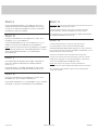
ÉTAPE 8
Enfoncer deux EXCENTRIQUES ESCAMOTABLES (1) dans
le DESSOUS (H).
Fixer le DESSOUS (H) à l’EXTRÉMITÉ GAUCHE (B). Serrer deux
EXCENTRIQUES ESCAMOTABLES.
ÉTAPE 7
Enfoncer quatre EXCENTRIQUES ESCAMOTABLES (1) dans les
TABLETTES (F et G).
Fixer l'EXTRÉMITÉ GAUCHE (B) aux TABLETTES (F et G). Serrer
quatre EXCENTRIQUES ESCAMOTABLES.
ÉTAPE 6
Fixer les MOULURES DE TABLETTE (N) aux TABLETTES (F et G).
Utiliser six VIS TÊTE GOUTTE DE SUIF 13 mm NOIRES (8) à travers
les CONSOLES EN MÉTAL sur les MOULURES DE TABLETTE et
dans les TABLETTES.
ÉTAPE 5
Fixer la TABLETTE INFÉRIEURE (G) au MONTANT INFÉRIEUR (D).
Utiliser deux VIS TÊTE PLATE 30 mm NOIRES (6).
ÉTAPE 4
Faire tourner deux VIS D'EXCENTRIQUE (2) dans les trous exacts
illustrés dans la TABLETTE SUPÉRIEURE (F).
Enfoncer deux EXCENTRIQUES ESCAMOTABLES (1) dans le
MONTANT INFÉRIEUR (D).
Fixer le MONTANT INFÉRIEUR (D) à la TABLETTE SUPÉRIEURE (F).
Serrer deux EXCENTRIQUES ESCAMOTABLES.
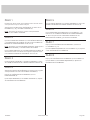
ÉTAPE 3
Fixer la TABLETTE SUPÉRIEURE (F) au MONTANT SUPÉRIEUR (C).
Utiliser deux VIS TÊTE PLATE 30 mm NOIRES (6).
ÉTAPE 2
Fixer neuf CONSOLES EN MÉTAL (3) à la PLINTHE AVANT (J)
et aux MOULURES DE TABLETTE (N). Utiliser neuf VIS TÊTE
GOUTTE DE SUIF 13 mm NOIRES (8).
REMARQUE : L'extrémité courte de la CONSOLE EN MÉTAL doit
être fi xé à la PLINTHE AVANT et aux MOULURES DE TABLETTE.
Fixer les PORTE-CARTES (4) aux MOULURES DE TABLETTE (N)
exactement comme l'indique le schéma agrandi. Utiliser huit VIS
À MÉTAUX 8 mm NOIRES (9).
ÉTAPE 1
Assembler l'élément sur un sol à moquette ou sur le carton vide
pour éviter d'endommager l'élément ou le sol.
Faire tourner dix-huit VIS D'EXCENTRIQUE (2) dans les
EXTRÉMITÉS (A et B) et le DESSUS (E).
REMARQUE : S’assurer d’utiliser les trous exacts illustrés dans
le DESSUS.
Page 20 www.sauder.com 422647
La page est en cours de chargement...
La page est en cours de chargement...
La page est en cours de chargement...
La page est en cours de chargement...
La page est en cours de chargement...
La page est en cours de chargement...
La page est en cours de chargement...
La page est en cours de chargement...
-
 1
1
-
 2
2
-
 3
3
-
 4
4
-
 5
5
-
 6
6
-
 7
7
-
 8
8
-
 9
9
-
 10
10
-
 11
11
-
 12
12
-
 13
13
-
 14
14
-
 15
15
-
 16
16
-
 17
17
-
 18
18
-
 19
19
-
 20
20
-
 21
21
-
 22
22
-
 23
23
-
 24
24
-
 25
25
-
 26
26
-
 27
27
-
 28
28


Sauder Storage Organizer 422647 Mode d'emploi
- Taper
- Mode d'emploi
dans d''autres langues
Documents connexes
-
Sauder Storage Cabinet Mode d'emploi
-
-
-
-
-
-
-
-
-