AMC SMILE 16/P Guide de démarrage rapide
- Catégorie
- Détecteurs de mouvement
- Taper
- Guide de démarrage rapide

www.amcelettronica.com
Installation Instructions v1.1
SMILE 16 Digital Pir Detector
1
SMILE 16 è un sensore ad infrarosso pet immune fino a 10kg di tipo digitale con microcontrollore. Grazie
all’ innovativo sistema di acquisizione e elaborazione numerica del segnale (AMC DMS - Digital Modulation
System) proveniente dal piroelettrico (2 elementi) è in grado di garantire una copertura in lunghezza di ol-
tre 18 mt e in larghezza di oltre 90°, garantendo un’assoluta sicurezza contro i falsi allarmi. E’ dotato di un
regolatore di portata con il quale è possibile settare la sensibilità da 3 a 18 mt, ha un contatore a doppio im-
pulso con finestra di tempo di 5”, attivabile in caso di installazioni dove sia richiesta una protezione maggiore
contro i falsi allarmi. L’ingegnerizzazione meccanica è stata realizzata in modo tale da non utilizzare viti, sia
per il fissaggio della scheda all’interno della cover che per l’apertura del sensore stesso. Per accedere alla
scheda elettronica sarà sufficiente fare pressione su un tasto sul fondo della cover (vedi figura) e, facendo
leva sui blocchetti in ABS, si potrà estrarre la scheda elettronica e lavorare in piena libertà. Grazie all’ingres-
so di BLOCCO SENSORE (B/S) è possibile attivare e disattivare il led di Walk Test senza aprire la cover.
1. INTRODUZIONE
SMILE 16/P
SENSORE INFRAROSSO DIGITALE PET IMMUNE
DIGITAL PIR DETECTOR PET IMMUNE
DETECTEUR INFRAROUGE ANIMAUX IMMUNIS
INSTALLAZIONE
INSTALLATION
ITALIANO
2. INSTALLAZIONE
- Utilizzando uno strumento sottile (esempio mini cacciavite a taglio), spingere il tastino tondo sul lato ante-
riore del sensore (vedi figura 1) e aprire la cover.
- rimuovere la scheda elettronica dal fondo della cover facendo leva sulla clips lato morsetti
(figura)
- forare gli sfondabili che si desidera utilizzare per il fissaggio, oppure utilizzare l’apposito snodo (opzionale).
Altezza consigliata per il fissaggio 2m
- fare scorrere il cavo di collegamento attraverso l’apposita guida sul retro della cover facendolo uscire dal
foro in alto (figura)
- cablare il circuito seguendo la guida ai collegamenti (figura 3).
ATTENZIONE: Non oscurare parzialmente o totalmente il campo di visione del rivelatore.
3. COLLEGAMENTO E REGOLAZIONE
Per quanto riguarda il collegamento alla centrale fare riferimento allo schema 3.
- Per disabilitare completamente il LED WALK TEST è necessario fornire una tensione 13.8 VDC fissa al
morsetto B/S, al contrario se si desidera disabilitarlo solo a sistema disarmato collegare un positivo solo a
centrale disinserita, oppure fare un pull up con una resistenza da 1 KΩ sul morsetto B/S e collegarlo ad una
uscita open collector di stato impianto della centrale. (vedi schema 3.)
- Con il JUMPER 1 è possibile configurare il sensore a dare allarme con 1 o 2 rilevazioni (JP1 APERTO =
1 impulso, CHIUSO = 2 impulsi in 5”)
- E’ possibile regolare la portata da 3 mt a 18 mt, normalmente in un impiego di tipo residenziale dove i
locali protetti non sono eccessivamente grandi è consigliato regolare il trimmer a metà corsa.
1. INTRODUCTION
ENGLISH
COMPLIANT
EN50131-2-2:2008
SMILE 16 is a pet immune 10kg digital, microprocessor-controlled PIR. Due to its innovative numerical
sampling and processing (AMC DMS - Digital Modulation System) of the PIR signal (2 elements), it has a
detection range of up to 18 m away from the detector with an angle of over 90° and allows to distinguish the

www.amcelettronica.com
Installation Instructions v1.1
SMILE 16 Digital Pir Detector
1
2. INSTALLATION PROCEDURE
- By using a thin screwdriver, push the round tooth on the bottom (see figure 1) and open the housing
- Remove the PCB from the base (figure)
- Use a screwdriver to pierce the knockouts on the side of the base where you wish to attach the detector to
the wall or use the optional swivel bracket. (height)
- Route the wires via the rear channel into the base and let them pass through the hole on the top of the
housing (see figure)
- Wire up the terminals following the connections shown in figure 3.
CAUTION: Do not partially or totally obscure the field of view of the detector
3. CONNECTIONS AND SETTINGS
As for the connections with the control unit please refer to figure 3.
- To disable the LED WALK TEST you have to apply a voltage of +13,8 VDC at terminal B/S, while if you
want to disable it only when the control unit is disarmed connect a plus voltage only when the system is
disarmed. If the control unit does not have a plus voltage command, but a ground voltage command, con-
nect the terminal B/S to both the power supply plus, through a 1 KΩ resistor, and to a system status open
collector output (ground voltage output) of the control unit (see figure 3)
- With JUMPER 1 it is possible to determine if the detector trigger an alarm after 1 or 2 consecutive motions
(JP1 OPEN = 1 impulse, CLOSED = 2 impulses within 5 sec.)
- It is possible to adjust the coverage within the range 3 m to 18 m. In an usual residential premise it is sug-
gested to regulate the trimmer at half its range.
1. INTRODUCTION
FRANÇAIS
Le SMILE 16 est un détecteur infrarouge digital avec animaux immunisés jusqu’à 10 kg . Grâce à l’innovant
système d’acquisition et de traitement numérique du signal (AMC DMS - Digital Modulation System) du
détecteur pyroélectrique (2 éléments), une portée de 18m et un angle de couverture de 90° garantissent
une protection optimale contre les déclenchements intempestifs.
Le SMILE 16 est équipé d’un régulateur de portée avec lequel il est possible de règler la sensibilité de 3 à
18 m et d’un comptage d’impulsion avec une fenêtre de temps de 5” activable dans les cas où est requise
une haute protection contre les déclenchements intempestifs.
La conception mécanique a été réalisée de telle façon à ne pas utiliser de vis pour la fixation de la platine
électronique à l’intérieur du détecteur et pour l’ouverture du capot du SMILE 16.
2 INSTALLATION
Pour l’installation, ouvrir le détecteur en pressant sur le petit clip se trouvant dans la partie inférieure à l’aide
d’un petit tournevis (voir fig1) puis déclipser la platine électronique (voir fig 2).
Défoncer les pré-percements ou utiliser une rotule suivant le type d’installation puis faire sortir le cable de
raccordement dans la partie supérieure et fixer le fond.
ATTENTION: Ne pas occulter partiellement ou totalement le champ de vision du détecteur.
true motion from any other disturbances causing false alarms. It features a regulator to adjust its range from
3 m to 18 m and a double-impulse event counter with a time window of 5 sec., selectable in installations
where an improved protection against false alarms is required. The housing does not require any screws
neither to fasten the electronic board to the base nor to open the detector. To disassemble the detector just
press the tooth on the bottom of the case (see figure) and pull out the PCB by pushing the clip and by lever-
ing on the ABS supports (see figure). In this way it will be possible to freely work on the PCB. Thanks to the
terminal BLOCK SENSOR (B/S) it is possible to activate and disable the Walk Test LED without opening
the housing.
3 CABLAGE ET REGLAGE
Cabler le détecteur en respectant la polarité (voir fig 3).
Il est possible de désactiver la LED de test en activant l’entrée B/S par une tension (voir fig 3).
Sélection du comptage d’impulsion grâce au jumper JP1(voir fig 4) Ouvert = 1 impulsion; Fermé = 2 impul-
sions de 5”. Pour le réglage de la portée de l’infrarouge de 3 m à 18 m, procéder comme suit :
- Mettre le potentiomètre “COVERAGE” au minimum (sens anti horaire) puis augmenter celui-ci (sens horai-
re) pas à pas afin d’obtenir la portée desirée.

www.amcelettronica.com
Installation Instructions v1.1
SMILE 16 Digital Pir Detector
2
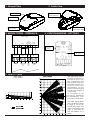
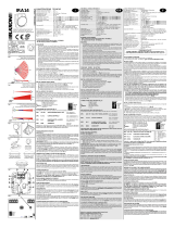
5. LENTE / LENS
AMC DMS (Digital Modula-
tion System) permette una
copertura di 18 mt, la spe-
ciale conformazione della
lente permette un’apertura
orizzontale di oltre 90° con
29 fasci su 5 livelli. (5 an-
tiavvicinamento, 6 a corta
portata,7 a media portata,6
a media lunga portata,5 a
lunga portata).
Si raccomanda di non
oscurare ne parzialmente
ne completamente il cam-
po di visione del rilevatore.
AMC DMS (Digital
Modu-
lation System) it allows
a range of 18 mt, the
special lens shape pro-
vides a horizontal cove-
rage of more than 90°
with 29 patterns on 5
levels.
1. General View 2. Inside View
3. MORSETTIERA - TERMINALS 4. CONFIGURAZIONE - SETTINGS
Premere qui per aprire
Press here to open
Led WALK TEST
Lente / Lens
Sfondabili per fissaggio
Mounting knockouts
Fissaggio circuito
Clip for electronic board
CENTRALE
CONTROL PANNEL
24H 13.8VDC
-+
OPEN
COLLECTOR
ARM/DISARM
ALARM
CONTACT
TAMPER
SUPPLY B/S N.C.
TAMPER
ALLARME
ALARM
ALIMENTAZIONE
SUPPLY
13.8
STOP
WALK
TEST
1K
N.O. 1 count
N.C. 2 count
COVERAGE
From 3 mt
to 18 mt

www.amcelettronica.com
Installation Instructions v1.1
SMILE 16 Digital Pir Detector
3
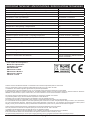
Alimentazione / Input Voltage / Alimentation 9 to 15 Vdc
Consumo / Current Drain / Consommation: (Alarm/Stand-By) (7.6 mA/10 mA) @ 13.8 Vdc
Portata in lunghezza / Coverage / Portee: from 3 to 18 m
Portata in larghezza / Angle / Angle de couverture 90°
Piroelettrico / PIR / Pyroelettrique 2 elementi / 2 elements
Lente / Lens / Lentille 29 patterns on 5 levels
Durata allarme / Alarm period / Duree alarme 4 sec.
Compesazione termica / Thermical compesation / Compensation thermique
✔
Antiapertura / Anti-opening / Autoprotection
✔
Antistrisciamento / Creep zone / Detection sous le detectour
✔
Contatto di allarme / Alarm contact / Contact d’alarme max 100 mA - 40 Vdc - 16 Ω
Contatto di tamper / Tamper switch / Contatct d’auto-protection max 40 mA - 30 Vdc
Contatore impulsi / Event counter / Comptage d’impulsion 2 count. for 5 sec. (selectable)
Temperatura di esercizio / Operating temperature / Temperature de fonction-
nement
from -10 °C to +55 °C
Temperatura di stoccaggio / Storage temperature / Temperature de stockage from -20 °C to +60 °C
RFI Protezione / Protection / Protection 10 V / m (20 MHz - 2000 MHz)
Led WALK TEST
✔
WALK TEST Ingresso / Input:/ entreé
✔
Cover / Housing / Boiter ABS
Accessori / Accessories / Accessoires snodo orientabile / Swivel bracket /
Rotule orientable*
Dimensioni / Dimensions 110 x 60 x 46 mm
SPECIFICHE TECNICHE / SPECIFICATIONS / SPECIFICATIONS TECHNIQUES
Prodotto conforme alla Direttiva 99/5/CE. La dichiarazione di conformità è disponibile presso la nostra sede.
Tutti i ns. prodotti sono conformi ai requisiti richiesti dalla norma CEI 79-2 2°ed. 1998 + Ab 2000.
L’installazione deve essere eseguita a regola d’arte da personale specializzato.
Il produttore declina ogni responsabilità nel caso in cui il prodotto venga manomesso da persone non autorizzate.
Si raccomanda di verificare il corretto funzionamento del sistema d’allarme almeno una volta al mese, tuttavia un sistema di allarme elettronico
affidabile non evita intrusioni, rapine, incendi o altro, ma si limita a diminuire il rischio che tali situazioni si verifichino.
This product comply the 99/5/CE directive. The declaration of conformity is available at our offices.
Our products/systems comply with the essential requirements of EEC directives.
Installation must be carried out following the local installation norms by qualified personnel.
The manufacturer refuses any responsibility when changes or unauthorized repairs are made to the product/system.
It is recommended to test the operation of the alarm product/system at least once a month. Despite frequent testing and due to, but not limited to,
any or all of the following: tampering, electrical or communication disruption or improper use, it is possible for the product/system to fail to prevent
burglary, rubbery, fire or otherwise. A properly installed and maintained alarm system can only reduce the risk that this happens.
Produit conforme à la Directive 99/5/CE. La déclaration de conformité est disponible chez notre société.
Tous nos produits sont conformes aux requises prévu par la norme CEI 79-2°ed. 1998 + Ab 2000.
L’installation doit ètre effectuée dans les règles de l’art par un installateur qualifié.
AMC Elettronica S.r.l. décline toute responsabilité en cas d’utilisation des produits par des personnes non habilitées.
Il est recommandé de vérifier le bon fonctionnement du système d’alarme au moins une fois par mois.
Un système d’alarme électronique n’exclut pas le risque d’intrusion, de vol, d’incendie mais limite et diminue fortement celui-ci
Meets the requirements:
Conforme ai requisiti:
R&TTE 99/5/CE
EN 50131-2-2: 2008
EN 50131-2-2 Grade 2
EN 50131-2-2 Class 2
CEI 79-2: I° Level
*: Non coperto da omologazione .
-
 1
1
-
 2
2
-
 3
3
-
 4
4


AMC SMILE 16/P Guide de démarrage rapide
- Catégorie
- Détecteurs de mouvement
- Taper
- Guide de démarrage rapide
dans d''autres langues
- italiano: AMC SMILE 16/P Guida Rapida
- English: AMC SMILE 16/P Quick start guide
Autres documents
-
 Elkron IRA 14 Guide d'installation
-
Marmitek MS845 Manuel utilisateur
-
-
Pyronix KX15DT Manuel utilisateur
-
Ris RWT312PR800A Manuel utilisateur
-
-
Risco Industrial LuNAR RK200DTG3 Guide d'installation
-
DSC LC-104-PIMW Le manuel du propriétaire
-
Risco BWare RK515DTGL Manuel utilisateur
-
