
SHARP
&
000
NNW
SERVICE
MANUAL/SERVICE-ANLEITUNG/
MANUEL
DE
SERVICE
“’
,_
-,
I
1
--^
ATSM282021PLY
FOTO:
RP-2m-l
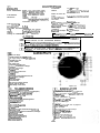
GENERAL
Power supply source:
Power rating:
Dimensions:
Weight
(including dust cover)
:
DRIVING SYSTEM
Type:
Motor:
Speeds:
Wow and flutter:
RP-200H
RP-200HB
RP2OOE
-
In the interests of user-safety the set should be restored to its
original condition and
only
parts identical to those specified be
used.
-
Im lnteresse der
Benutzer-Sicherheit
sollte dieses
Gerlt
wieder
auf seinen
ursprikglichen
Zustand
eingestellt
und
nur
die
vorgeschriebenen Teile
verwendet
werden.
-
Dans
I’interbt
de la securite de
I’utilisateur,
I’appareil
devra
etre
reconstitue
dans
sa
condition premiere et
seules
des pieces
identiques
a
celles
specifiees,
doivent
Btre utilisees.
i
SPECIFICATIONS
AC 1
lOV~12OV/22OV~24OV,
50 Hz or 60 Hz
(RP-200H/HB)
AC
24OV,
50 Hz
(RP-200E)
low
Width; 390 mm
Height (including dust cover);
123 mm
Depth; 350 mm
4.2 kg
Rumble:
Turntable:
TONEARM
Type:
Effective length:
CARTRIDGE
Type:
Frequency response:
output:
Channel separation:
60
dB (DIN
“B”)
30 cm die-cast
aluminium
Statically balanced tubular arm
215 mm
Magnetic type
20 Hz
-
20,000 Hz
Somali
volts (1
kHz,
50
mm/set.)
Belt drive
4-pole synchronous
33-l
I3
rpm and 45 rpm
&0.15%
(DIN)
Tracking force:
Impedance:
’
Compliance:
2 grams, (recommended)
47 kilo ohms
7
x
10e6
cm/dyne
Specifications for this model are subject to change without
prior notice.
TECHNISCHE
DATEN
ALLGEMEINE
DATEN
Spannungsversorgung:
Netzspannung 11
OV.
12OV/22OVa
24OV,
50 Hz oder 60 Hz
(RP-200H/HB)
Netzspannung
24OV,
50 Hz
(RP-200E)
Leistungsaufnahme:
low
Abmessungen: Breite; 390 mm
Hohe (einschlieRlich Abdeckhaube);
123 mm
Tiefe; 350 mm
Gewicht (einschlieRlich
Abdeckhaube)
:
4,2
kg
ANTRIEBSSYSTEM
TYP:
Riemenantrieb
Motor:
4-polig,
Synchronmotor
Drehzahlen:
33-l/3
und 45
U/min
Gleichlaufschwankungen:
&0,15%
(DIN)
Rumpelabstand:
Plattenteller:
60
dB
(DIN “B”)
30cm-Plattenteller
aus
Alminium.
spritzguS
TONARM
TYP:
Tonarmltinge:
Statischbalanceirter Rohrarm
215 mm
TONABNEHMERSYSTEM
TYP:
Magnet
Frequenzgang:
20
-
20
000
Hz
Ausgang:
Kanaltrennung:
;oMd;volt
(1
kHz,
50 mm/sek.)
Auflagekraft:
2 Gramm (empfohlener Wert)
Impedanz: 47
Kiloohm
Nachlaufvermdgen:
7
x
10m6
cm/dyne
Anderungen der technischen Daten dieses Modelles jederzeit
vorbehalten.

CD
CARACTERISTIQUES
GENERALITES
Ronflement:
60
dB
(DIN
“B”)
Source d’alimentation: Secteur 1
lOV.12OV/22OV.24OV,
Plateau: 30
cm de
diametre en aluminium
50Hz
ou
60Hz
(RP-200H/HB)
coule
sous
pression
Secteur
24OV,
50Hz
(RP-200E)
BRAS DE PICK-UP
Consommation:
IOW
Type:
Tubulaire equiiibre
statiquement
Dimensions: Largeur;
390 mm
Longueur efficace:
215 mm
Hauteur (y compris
le
cache-poussiere);
123
mm
Profondeur; 350 mm
CELLULE
Type:
Reponse
en frequence:
Tension de sortie:
Separation des canaux:
Poids
(y
compris
le
cache-poussiere):
4,2
kg
SYSTEME D’ENTRAINEMENT
Type
:
Entrainement par courroie
Moteur:
Quadripolaire,
synchrone
Force d’appui:
Impedance:
Elasticite acoustique:
Magnetique
20
Hz
a
20.000 Hz
3
mV
(1
kl-iz, 50
mm/set.)
20
dB
2 grammes (recommandes)
47k
ohms
7 x
10v6
cm/dyne
1
Les caracteristiques de ce modele sont sujettes
$
modifica-
tion sans
preavis.
Vitesses:
33-l/3
et 45
tours/mn.
Pleurage et scintillement:
iO,15%
(DIN)
m
1
FOR A COMPLETE DESCRIPTION OF THE OPERATION
OF
THIS
UNIT,
1
w
PLEASE REFER TO THE OPERATION MANUAL
CD
DIE
BEDIENUNGSWEISE
DIESES
GERATES
IST IN DER
BEDIENUNGS-
ANLEITUNG
AUSFUHRLICH
BESCHRIEBEN.
CD
POUR UNE DESCRIPTION COMPLETE
DU
FONCTIONNEMENT
DE CET
APPAREIL.
SE REPORTER AU MODE D’EMPLOI.
GB
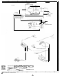
NAMES
OF
PARTS
Dust Cover Hinge
Spindle Adaptor for 45
rpm
Records
AC Supply Voltage Selector
(RP-200H/HB)
Turntable and Mat
Centre Spindle
AC Supply Cord
Output Socket with Lead
Tonearm Counterbalance Weight
Tracking Force Gauge
Tonearm
Lifter
Cuing/Pause Control Lever
Tonearm
Rest
Tonearm
Automatic Lead-in Adjustment Screw
@
Headshell
and Cartridge
@
Play Start Button
0
Cut-out Button
@
Record Size Selector Button
@
Speed Selector Button
@J
Anti-skating control knob
a
TEILEBEZEICHNUNG
@
Scharnier der Abdeckungshaube
@
Mittelstiick
fijr 45
U/min-Schallplatten
(Adaptor)
@
Netzspannungswahler
(RP-200H/HB)
@
Plattenteller
und
Auflage
@
Mittelachse
@
Netzzuleitungskabel
@
Ausgangsbuchsen
mit Verbindungskabel
@
Tonarmgegengewicht
@
Auflagekraftskala
@
Tonarmlifter
(J
Tonarmlift-/Pausenhebel
@
Tonarmstiitze
@
Tonarm
@
Einstellschraube
der automatischen
Einfiihrung
(Rtickfiihrung)
@
Tonabnehmertrtiger
und Tonabnehmer (Cartridge)
@
Abspieltaste
@
Unterbrechungstaste
@
Schallplattengrol3enwahler
@
Drehzahlenwlhler
@
Antiskatingssteller
Figure 2-l
CD
NOMENCLATURE
$
Charniere du
cache-poussieres
@
Adaptateur de mandrin pour
disques
45 tours
(3
Selecteur de tension de secteur
(RP-200H/HB)
(3
Plateau et tapis
(5)
Mandrin central
!@
Cordon d’alimentation de secteur
fa
Douille
de sortie
avec
fils
@)
Contrepoids du bras
:$
Jauge de force d’appui
(6)
Leve-bras
$@
Levier de commande de mise en pile/pause
173
Repose-bras
i”J
Bras acoustique
@
Vis de
reglage
d’entree
automatique
@
Coque de tdte et cellule
@
Bouton de depart en lecture
f@
Bouton de retranchement
@
Sdlecteur de
taille
du disque
/@
Selecteur de
vitesse
@
Bouton de commande antiskating
-2-
0

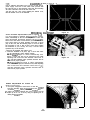
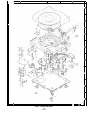
DISASSEMBLY
(Refer to Figure
3-1)
Prior to removing the bottom cover, be sure to draw the AC
power supply cord from a wall outlet. Then proceed with
the removal work in the following order after disconnecting
all of the connection cords at the rear of the unit.
Turn the unit over, nine screws retaining the bottom cover,
then the bottom cover can be detached.
L
MECHANICAL
ADJUSTMENT
Figure 3-l
AUTO RETURN ADJUSTMENT
(Refer to Figure
3-2)
If a record playing is finished, the tonearm must, usually,
return automatically to the rest stand by the aid of the auto
return mechanism functioning. However, the tonearm may
start to move even when a record doesn’t yet reach its extreme
end or there arises no return operation even after a record
play: in this case, take the following steps to correct it. (More,
the important to note is that if other record than meeting
the Standard of your country are used, a normal return
operation may not be ensured.
1. Remove the turntable and bottom cover.
2. Reset the turntable to its place, play a record and check
for the automatically return starting position.
* If the tonearm begins to return automatically even
before a record play has not yet reached its end, rotate
adjusting cam A and move the automatic return lever to
@
, until the automatic return operation becomes able to
start from its proper position.
* If the tonearm doesn’t begin to return automatically
even after a record play has reached its end, rotate adjusting
cam A and move the automatic return lever to
@
,
until the automatic return operation becomes able to
start from its proper position.
HEIGHT ADJUSTMENT OF STYLUS TIP
(Refer to Figure 3-3)
il
1. Lift up the cuing/pause control lever to raise the tonearm
and then manually bring the tonearm over the turntable
so that the
tonearm
will be put onto the tonearm lifter.
2..
Adjust the interval between the record surface and the
stylus tip to be 4 to 8 mm by using an adjusting nut re-
taining the tonearm lifter.
Figure 3-2
-3-
Figure 3-3

m
ZER
LEGEN
(Siehe Abbildung
3-l
1
Vor den Zerlegungsarbeiten mu8 unbedingt darauf geachtet
werden,
da13
das Netzzuleitungskabel
aus
der Steckdose vorher
entfernt wurde. Nach weiterem Entfernen der AnschluRkabel
auf der Riickseite des
Gerates
kann dann der
Zerlegungsvor-
gang in der folgenden Reihenfolge vorgenommen werden.
Das Gerat umdrehen
und
die 9 Befestigungsschrauben der
Bodenplatte durch Herausschrauben entfernen, wonach die
Bodenplatte abgenommen werden kann.
MECHANISCHE
EINSTELLUNG
EINSTELLUNG
DER
AUTOMATISCHEN
RUCKFUHRUNG
(Siehe Abbildung
3-2)
Bei
Beendigung des Abspielvorganges einer
Schailplatte
muR
der
Tonarm
normalerweise von der automatischen Ruckfiih-
rungsvorrichtung automatisch auf seine Tonarmstiitze zurijck-
gebracht werden.
Jedoch
konnte
es vorkommen,
daR
der
Ton-
arm
schx
vor Erreichen des Schallplattenendes mit dem
Rijckftihrvorgang beginnt oder selbst
nach
Beendigung des
Ab-
spielvorganges
nicht
automatisch auf die Tonarmstiitze zuriick-
gefiihrt wird. Dieses Vorkommen kann auf folgende Weise
korrigiert werden:
(Hierbei
muR
jedoch beachtet werden,
daR
bei
Verwendung
von ungenormten SchallplattengrGRen ein normaler Riickfiih-
rungsvorgang
nicht
gewahrleistet werden kann.)
1. Den
Plattenteller
und
die Bodenabdeckung abnehmen.
2. Den Plattenteller wieder an seinem Platz anbringen, eine
Schallplatte entsprechend abspielen und die Einsetzposi-
tion der automatischen Riickftihrung
Ciberpriifen.
* Falls der
Tonarm
schon
vor Erreichen des Schallplatten-
endes mit dem Rtickfiihrungsvorgang beginnen sollte, die
Einstellnocke A drehen
und
den automatischen
Rtickfiih-
rungshebel
auf die
la
Stellung
bewegen, bis der auto-
matische Rijckfiihrungsbetrieb von der richtigen Stelle an
einsetzen kann.
* Falls der
Tonarm
nach
dem Erreichen des Schallplatten-
endes nicht automatisch zurtickgefuhrt wird, die Einstell-
nocke A drehen und den automatischen
Ri.ickfBhrungs-
hebel
auf die
0
Stellung
bewegen, bis der automatische
Rtickfiihrungsbetrieb von der richtigen Stelle an einsetzen
kann.
‘-
HCHENEINSTELLUNG
DER
NADELSPITZE
(Siehe Abbildung 3-3)
1. Den
Tonarmlift-/Pausenhebel
betatigen,
urn
den
Tonarm
anzuheben. Den Tonarm dann manuell iiber den Platten-
teller bewegen, so
daR
der
Tonarm
auf den Tonarmlifter
gebracht wird.
2. Den Abstand zwischen der Schallplattenoberflache und der
Nadelspitze des Tonabnehmers dann auf 4 bis 8 mm
durch
entsprechendes Drehen der Einstellschraube des
Tonarmlif-
ters einstellen.
CED
DEMQNTAGE
(Voir la Figure
3-1)
Avant de deposer
le
couvercle de base, s’assurer de retirer
le
cordon d’alimentation de secteur, de la sortie murale.
Puis
proceder au travail de depose, dans I’ordre suivant
apres
avoir debranchd tous
les
cordons de connexion
situ&
au
dos de I’appareil.
Puis
retourner I’appareil, deposer
les
9 vis de retenue du
couvercle de base et deposer
le
couvercle de base.
REGLAGE
DU
MECANIQUE
REGLAGE DU
RETOUR
AUTOMATIQUE
(Voir la Figure 3-2)
Si la lecture d’un disque est terminee,
le
bras
doit
generalement
revenir automatiquement
sur
son appui
grace
au
fonctionne-
ment
du
mecanisme de retour automatique. Toutefois,
le
bras
peut commencer
a
se deplacer avant que
le
disque soit
totale-
ment termine
ou
bien I’operation de retour n’a pas lieu meme
apres
la fin de la lecture
du
disque: dans ce cas suivre
les
etapes
ci-dessous pour corriger cet
&at.
(II est
t&s
important de noter
que
si
un
disque ne satisfait pas
les
Normes
du
pays d’utilisa-
tion, I’operation normale de retour ne peut pas
Btre
assuree.)
1. Deposer
le
plateau et
le
couvercle de base.
2. Remettre
le
plateau
B
sa place, iire
un
disque et verifier la
position de demarrage du retour automatique.
“Si
le
bras acoustique commence
a
revenir
automatique-
ment avant la fin de la lecture du disque tourner la came
de
reglage
A et deplacer
le
levier de
retour
automatique
vers
@
, jusqu’a ce
que
I’operation de
retour
automatique
puisse demarrer
B
I’endroit approprie.
“Si
le
bras acoustique ne commence pas
B
revenir auto-
matiquement
aprbs
la fin de la lecture d’un disque, tourner
la came de
reglage
A et deplacer
le
levier de retour auto-
matique vers
0
jusqu’a ce que
I’operation
de
retour
automatique puisse demarrer
a
I’endroit approprie.
REGLAGE DE LA HAUTEUR DE LA
POINTE
DE
L’AIGUILLE (Voir la Figure 3-3)
1. Lever
le
levier de commande de mise en pile/pause pour
lever
le
bras et porter
a
la main,
le
bras au-dessus
du
plateau
de telle sorte que
le
bras
soit
place sur
le
live-bras.
2. A I’aide de l’ecrou de
reglage
de retenue du
l&e-bras,
regler
de telle sorte que I’intervalle entre la surface du
disque
et
la pointe de I’aiguille, soit de 4
a
8 mm.
-4-

CARTRIDGE
nr-L”“I
I
R
P-200H
B
31
Yy//
OUTPUT SOCKET
n
::
-i-
I
I
I
I
I
I
NOTE:
Parts marked with
“A”
(0
1
are important for maintaining the
safety of the set.
Be
sure to replace these parts with specified ones
for maintaining the safety and performance of the set.
(Specifications or wiring diagrams of this model are subject to change
for improvement without prior notice.)
Die mit
n
(
0)
bezeichneten Teile sind besonders
die
Aufrechterhaltung
der Sicherheit. Beim
Wechseln
c
sollten
die vorgeschriebenen Teile immer
verwendet
werden,
die Sicharheit
als
such die
Leistung
des
Gerates
aufrecht
(Anderungen
der technischen Daten oder Verdrahtungsp
Modelles
im Sinne der Verbesserung jederzeit
vorbehalten.)
1
/
2
I
3
I
4
I
5
I
6
Figure 5 SCHEMATIC
DIAGRA
-5-

RP-200E
TURNTABLE
I
WHITE
I
Y
OUTPUT SOCKET
-
“_
d
I,.
I
SW I
:
b
I
I
i,m
T’-.:
6;
.::
24OV
50H.s
dichtig fiir
eser
Teile
lrn
sowohi
:uerhalten.
ane
dieses
Les pieces
portant
une marque
A
(m)
sont
particulierement
importantes par securite. S’assurer de
les
remplacer par
des
pieces du
numero
de piece
specific
pour maintenir la securite et la performance
de
I’appareil.
(Les specifications des
schemas
de montage de ce modele
sont
sujettes
a
modification et amelioration
sans
preavis.)
v1
AND WIRING CONNECTION
-6-

r-l
I
2
3
4 5
/
6
I
1
1
2
3
I
4 5
r
6
L
I
L
-
E
-
C
-
0
-
E
-
F
-
3
-
-I
Figure 7 EXPLODED VIEW
-7-

Fixing position of
Connection
AC supply cord
AC supply cord holder
8
EC
Figure
QACCVOOOIAGZZ
Blue
Brown ,
+T
w*
QACCB0054AF09
Blue
Brown
G
e
QACCL0052AFZZ
Brand
Projection
stamp
stripe
w*
QACCZ0053AFOO
+z
Black
Black
w*
QACCZ0056AFOO
Brown
Brown
TABLE
1
AC SUPPLY CORD WIRING CONNECTIONS
0
\’
Supporting Plate
Caution Card
(912890816)
Mat, Turntable
Turntable
(912620076)
Turntable Spacer
Player Unit
Packing Add.
Left.
(912852681)
\
Counterbalance
Spindle Adaptor
-
(912890876)
Accessory Pad
Packing Add. Right
(912852681)
, Dust Cover
(GCOVAI
194AFSA)
Packing Case
(912852711-2
PACKING METHOD
(RP-ZOOE)

aREPLACEMENT
=ERSATZTElLLlSTE
OLISTE
DES PIECES
PARTS LIST
1
/
DE RECHANGE
“HOW TO ORDER REPLACEMENT
PARTS”
To have your order filled promptly and
correctly, please furnish the following
information.
1. MODEL NUMBER
2. REF. NO.
3. PART NO.
4. DESCRIPTION
“BESTELLEN VON ERSATZTELEN”
Urn lhren
Auftrag
sch’nell
und richtig
ausfiihren
zu
konnen,
bitten wir urn die
folgenden
Angaben.
1.
MODELLNUMMER
2.
REF.-NR.
3.
TEIL-NR.
4.
BESCHREIBUNG
“COMMENT
COMMANDER
DES
PIECES DE RECHANGE”
Pour
voir
votre
commande
e&cut&s
de
maniere rapide et
correcte,
veuillez
\es
renseignements suivants.
1. NUMERO DU MODELE
2.
No
DE REFERENCE
3.
No
DE LA PIECE
4. DESCRIPTION
Parts marked with “A
”
are important for
Die mit
A
bezeichneten Teile sind besonders
Les
pieces
portant
une marque
n
sont
parti-
maintaining the safety of the set. Be sure wichtig
fur
die
Aufrechterhaltung
der Sicher-
culierement
importantes
par
s&xi-ite.
S’assurer
to replace these parts with specified ones
heit.
Beim Wechseln dieser Teile
sollten
die
de
les
remplacer par des pieces du
numero
de
for maintaining the safety and performance vorgeschriebenen
Teile immer
verwendet
piece
specific
pour maintenir la
securite
et
of the set.
werden,
urn
sowohl
die Sicherheit
als
such la performance de
I’appareii
die Leistung des Gerates
aufrechtzuerhalten.
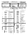
REF. NO.
PART NO.
DESCRIPTION CODE REF. NO. PART NO.
DESCRIPTION
CODE
MECHANICAL PARTS
21
22
1
2
3
J
912848945
)
912848945-1
91Z910578
912899734
23
24
25
912912197
91
z912279
912910712-2
9128967584
912891443-1
4
912891432
5
912891947-I
6 912891474
7
912899735
a
9 12899744
26
91z912310
27
91z912311
28
912910138-1
29
912897247
9
10
11
12
912873052-2
912899745
912873051-2
912891443-I
91 z912295
Cabinet
Assembly(RP-200H/E)
Cabinet Assembly
(RP-200HB)
Gear Assembly
Shaft,
Tonearm
Lifter
Cam with Gear
Lever, Switching Operation
(Large)
Lever, Clutch
Spring, Clutch Lever
Spring, Switching Lever
Lever, Switching
Lever, Play Start/Cut-out
Operation
Lever, Play Start/Cutout
Spring, Play Start/Cut-out
Lever
Screw, Play Start/Cut-out
30 912912198
31
912912199
32
91
Z912301
33
912912302
34
912896267-3
35
912832780
Guide, Power Switch Button
Cam, Play Start/Cut-out
Cam, Record Size Selector
Screw, Cam
Spring, Play Start/Cutout
Lever
Spring, 1
Spring, 2
Lever, Power Switch Guide
Bracket, Power Switch Guide
Lever/Cue Control Lever.
Guide, Turntable Belt
Cam, Speed Selector
Rod, Play Start/Cutout
Rod, Record Size Selector
Shaft, Tonearm Lifter
Spring, Tonearm Lifter
(Large)
Tonearm
Lifter
Nut,
Tonearm
Lifter
(Adjusting)
Spring, Tonearm Lifter
(Small)
Terminal Strip,
4-lug/2ground
Nylone
Band
Lug, Ground (with Lead)
Fiber
Tonearm Rest Assembly
Tonearm
Assembly
36
912899754-l
37
912896268
12-2 91
Z910862
123
912891485-l
124 912891850-l
125
912891005-1
13
912912293
14 912891435
Lever, Play Start/Cut-out
Switching
Spring, Play Start/Cut-out
Switching Lever
Clutch, Cam with Gear
Guide, Clutch
Screw, Gear
Record Size Selector
38
9lZ287680
39 912891849
912852712
42 912894408
91 ZMB-2570
44
91z912309
45
91
Z912308
46
91
Z910589
47
47-1
/
Assembly
Arm, Record Size Selector
Pin, Record Size Selector
Spring, Record Size Selector
Arm (Small
1
Guide, Record Size Selector
Arm
Pin, Record Size Selector Arm
47-2
BBMCART-126
,473
BBMSTY -120
48
91
Z910854-1
49
912891443-2
50
51
91Z912296
912872669-I
91
Z912330
52
911099-I
53
912897554
54
910633-5
55 912897547
56
91
ZE-10002-31
58 912912307
59 912893914
60
912873378
Weight with Tracking
Force Gauge
Cartridge
Stylus
Tonearm
Counterbalance
Lever, Record Size Selector
Spring, Record Size Selector
Lever
Lever, Tonearm Control
Lever, Automatic Return
Knob, Anti-skating Control
(RP-200H/E)
Knob, Anti-skating Control
(RP-200HB)
Washer, Anti-skating Control
Knob
Spring, Anti-skating Control
Cam, Anti-skating Control
Terminal Strip,
2-log/l-ground
Lever, Cuing/Pause Control
Knob, Cuing/Pause Control
Lever, Cuing/Pause Control
Operation
912891433
&l4-2
912891058-2
15
912891443-3
16
91
Z910861
17
912912292
18
912872667
Rotation Plate Assembly
18-1
912899750
Rotation Base
18-2
18-3
184
185
186
18-7
18-B
19
Spring, Rotation Ease
Pin, Rotation Base
Rotation Arm
Shaft, Friction Drive
Spring, Friction Drive Shaft
Rubber Tip, Friction Drive
Shaft, Rotation Arm
Screw, Rotation Plate
Button, Play Start, Cut-out
Record Size Selector, Speed
Selector
(RP-200-H/E)
Button, Play Start, Cut-out
Record Size Selector, Speed
Selector
(RP-200HB)
912895021
91
Z910085-1
912872666
912910086
91
Z910087-1
912891452-l
912891064
912912294
I
912912196
912912196-I
20
-9-

REF. NO. PART NO.
DESCRIPTION
CODE
REF. NO.
PART NO. DESCRIPTION
CODE
n
62
63
912852672-I
64
912892227
65
912620076
66
912872641
67
9127005158
68
91z912300
70
71
73
74
75
76
78
n
Cl
912898550-i
GCOVAI
194AFSB
GCOVAI
194AFSA
91
Z912303
912896147-I
91
Z703740-2A
912703740-28
912702230
9128930574
91
Z912304
91
Z912304-1
Holder AC Supply
Cord
Cover, Bottom
Leg, Rubber
Turntable
Rubber Mat, Turntable
Belt, Turntable
Bearing Assy, Turntable
Shaft Assembly
Dust Cover
(RP-200H/HB)
Dust Cover
(RP-200E)
Hinge, Dust Cover
Braket, Motor
Pulley, 50 Hz
Pulley, 60 Hz
Cushion, Rubber, Motor
Screw, Motor Retaining
Specification Label
(RP-200H)
Specification Label
(RP-200HB)
91
Z912304-2
Specification Label
(RP-200E)
912890876
Spindle Adaptor
912892674
No Card
AX
MISCELLANEOUS
RCKZ067CAFZZ
O.OlMFD,
4OOV. +lOO
-0%,
AG
Ceramic
Ml
:
912632163
912632162
912895891
912870270
QSW-S0285AFZZ
912897940
912890816
912893062-l
912852681
912852711
91285271 l-1
912852711-2
QACCL0052AFZZ
QACCVOOI AGZZ
QACCZ0053AFOO
QACCZ0056AFOO
QACCB0054AF09
TCAUH0249AFZ.Z
TCAUSO076AFZZ
TCAUH0056AGZZ
TCAUZOO39AFZZ
TINSZ0359AFZZ
TINSE0775AFZZ
Motor
(IMS2758D)
(RP-200H/HB)
Motor
(IMS-275i3C)
(RP-200E)
Output
Socket with Lead
Switch, Main
Switch, Voltage Selector
(RP-200H/HB)
Turntable Spacer
Caution Card
Screw, Motor Retaining
Packing Add. (Right, Left)
Packing Case
(RP-200H)
Packing Case
(RP-200HB)
Pacing Case
(RP-200E)
AC
Suply
Cord
)
AC
Suply
Cord
Refer
to
AC
SAPPY
Cord ,
TABLE
,
AC
Suply
Cord
AC
Suply
Cord
(Page
a)
(RP-200E)
]
Caution Card, Voltage
Selector
(RP-200H)
Caution Card
(RP-200H)
Caution Card
(RP-200E)
Caution Card
(RP-200E)
Operation Manual
(RP-200H/HB)
Operation Manual
(RP-200E)
Writer and Editor: Engineering Administration of Audio Systems Group, Sharp Corp.
AH
AL
AK
AK
AB
AA
AF
[A82028289N
K
Printed
in
Japan
In Japan
gedrhck.
Imprime
au
Japol
-
 1
1
-
 2
2
-
 3
3
-
 4
4
-
 5
5
-
 6
6
-
 7
7
-
 8
8
-
 9
9
-
 10
10


Sharp RP-200HB Manuel utilisateur
- Taper
- Manuel utilisateur
dans d''autres langues
- English: Sharp RP-200HB User manual
- Deutsch: Sharp RP-200HB Benutzerhandbuch
Autres documents
-
Dual 1254 Le manuel du propriétaire
-
Hitachi HT-L55 Manuel utilisateur
-
Rotel RP-560 Le manuel du propriétaire
-
-
-
Grundig PS2500 Le manuel du propriétaire
-
Denon DP-30L Le manuel du propriétaire
-
-
-
Marantz TT-42 Manuel utilisateur