
Professional
UHF Wireless Systems
ATW-DA600
Diversity UHF Antenna Distribution System, 656-680 MHz
ATW-DA700
Diversity UHF Antenna Distribution System, 728-752 MHz
Installation and Operation

Front Panel Controls and Functions (Fig. A)
1. POWER SWITCH: Press switch On ( I ) to apply AC power to unit.
2. POWER INDICATOR: Shortly after power is applied, the indicator will light.
Figure A: ATW-DA600 front view
ATW-DA600 and ATW-DA700 Installation and Operation
AVIS
RISQUE DE CHOC
ÉLECTRIQUE
NE PAS OUVRIR
CAUTION
RISK OF ELECTRIC
SHOCK
DO NOT OPEN
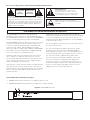
Caution/Avis:
Replace with same type 2.5A 250V fuse.
Utiliser un fusible de rechange de même type de
2.5A 250V.
2.5A 250V
To prevent electric shock, do not remove the cover. There are no
user-serviceable parts inside. Internal adjustments are for qualified
professionals only. Refer all servicing to qualified service personnel.
Pour prévenir un choc électrique, ne pas ouvrir le couvercle. Il n’y
aucune pièces de rechanges à l’intérieur. Tout ajustement interne
doit être fait par une personne qualifié seulement. Référez tout
réparation au personnel qualifié.
Warning/Attention:
To prevent fire or shock hazard, do not
expose this appliance to rain or moisture.
Pour prévenir feu ou choc électrique, ne pas
exposé l’appareil à la pluie ou à l’humidité.
Prior to use of this product, review all safety markings and instructions.
The ATW-DA600 is a UHF active unity-gain antenna
distribution system operating over the 656-680 MHz range.
The ATW-DA700 is identical in all respects to the ATW-DA600
except for its operating frequency range: 728-752 MHz.
The ATW-DA600 provides two identical sections, one for each
antenna of a UHF diversity wireless system. Each section
in the unit comprises an antenna input, four bandpassed,
isolated receiver outputs, and a bandpassed “cascade”
directional coupler to supply signal to additional ATW-DA600
units. All RF connectors are BNC-type. Ten BNC-to-BNC RF
interconnect cables are included with the unit.
Antennas can be remotely located from the unit. However,
due to signal loss in cables at UHF frequencies, use the
lowest-loss RF cable type(s) practical for any cable runs over
25 feet. RG-8 is a good choice. Use only copper-shielded
cable, not CATV-type foil-shielded wire.
Either passive or active antennas may be used. Both antenna
input jacks provide +12V DC output on their center pins to
operate Audio-Technica powered antennas or other in-line RF
devices, if desired. Up to 250 mA can be drawn from each
antenna input jack.
Additionally, four jacks on the rear panel provide 12V DC
(center
positive
) to power as many as four receivers operating
on 12 volts at 350 mA each. Included with the unit are four
polarity-inverting DC cables appropriate for use with ATW-R73
(or like-powered) receivers.
The 12-volt supplies for powering receivers and in-line devices
are short-circuit protected.
The unit’s switching power supply is designed to operate
properly from any AC power source 100-240V, 50/60 Hz
without adjustment. Simply connect to a standard AC power
outlet, using an IEC input cordset approved for the country of
use. The unit normally is supplied with a 120V cordset.
The unit includes pre-installed rack adapters (“rack-mount
ears”) for mounting in a standard 19" rack. (#10-32 rack-
mounting screws are not included.) If rack mounting is not
required, the adapters may be removed by simply taking out
the three screws holding each adapter in place. Save the
adapters and screws for possible future use.
1
2

Specifications
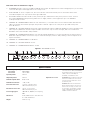
Figure B: ATW-DA600 rear view
ANTENNA A OUTPUT
1
2
3
4
1
2
3 4
POWER
INPUT
100-240V AC
50-60 Hz
60 W
OUTPUT
12V DC
350 mA
CLASS 2
CASCADE
ANTENNA B
INPUT
CASCADE
ANTENNA A
INPUT
OUTPUT
12V DC
350 mA
CLASS 2
+
+
12V DC
250 mA CLASS 2
ANTENNA B OUTPUT
12V DC
250 mA CLASS 2
Useable Frequency Range
ATW-DA600 656-680 MHz
ATW-DA700 728-752 MHz
Input Impedance 50 ohms
Output Impedance 50 ohms
Nominal Amplifier Gain 0 dB, ±3 dB
Nominal Cascade Gain –3 dB, ±3 dB
In-line Antenna Power +12V DC on RF input jacks,
250 mA maximum per jack
External Receiver Power 12V DC, center
positive
,
350 mA maximum per jack
Power Supply Input 100-240V AC, 50/60 Hz, auto-adjusting,
60W
Dimensions 16.93" (430.0 mm) W x 1.92" (48.8 mm)
H x 7.60" (193.0 mm) D
Weight 5.9 lbs (2.7 kg)
3
Rear Panel Controls and Functions (Fig. B)
3. AC POWER: IEC-type connector for 100V to 240V AC power input. No adjustment for mains voltage/frequency is necessary;
connect an IEC input cordset approved for the country of use.
4. FUSE HOLDER: To check or replace fuse, disconnect the AC cordset and carefully remove the holder with a small
screwdriver. Replace fuse only with the same type 250V 2.5A.
5. DC OUTPUT JACKS: Provides 12V DC (center
positive
) at up to 350 mA from each jack to power receivers. Connect
the included ATW-RDCP polarity-inverting cables here to supply 12V DC (center
negative
) to up to four ATW-R73
(or like-powered) receivers.
6. CHANNEL “B” ANTENNA INPUT: Attach the “B” antenna here, or extend it with a low-loss antenna cable. (Antenna and
cable not included.) The antenna input jack also provides +12V DC output on its center pin at up to 250 mA to power
in-line RF devices.
7. CHANNEL “B” CASCADE OUTPUT: Directional coupler provides RF output to additional distribution systems operating in the
same frequency band. Each cascade output should be connected to only one other unit input, and no more than three
distribution units total should be “daisy-chained.”
8. CHANNEL “B” DISTRIBUTION OUTPUTS: Four jacks provide RF distribution to receivers operating in the same frequency
band. Each output should be connected to only one other antenna input, without “daisy-chaining.” Unused outputs do not
require termination.
9. CHANNEL “A” ANTENNA INPUT: See #6 above.
10. CHANNEL “A” CASCADE OUTPUT: See #7.
11. CHANNEL “A” DISTRIBUTION OUTPUTS: See #8.
Accessories Included 1 120V power cordset, 10 BNC-to-BNC
1.5' interconnect cables, 4 ATW-RDCP
DC polarity-inverting 1.5' interconnect
cables, 2 rack-mount adapters
(installed), 4 self-adhesive feet.
Optional Accessories ATW-RDCN: Non-polarity-inverting DC
interconnect cables (set of four). For
use with receivers that have center
positive
DC jacks.
ATW-RA1: Rack-mount antenna kit
brings antenna inputs to the front of
unit for ease of setup, or when unit
is enclosed in a metal rack. Includes
a pair of adjustable-length antennas
suitable for UHF or VHF use.
4
6
7 8
9
10
11 55

Extensive information about using wireless systems and accessories is available on the Audio-Technica Web site at
www.audio-technica.com
Audio-Technica U.S., Inc.,
1221 Commerce Drive, Stow, Ohio 44224 330/686-2600
Audio-Technica Limited, Old Lane, Leeds LS11 8AG England (0)113 277 1441
P51317-B/W ©2001 Audio-Technica U.S., Inc. Printed in U.S.A.
One-Year Limited Warranty
Audio-Technica professional wireless systems purchased in the U.S.A. are warranted for one year from date of purchase by Audio -Technica U.S., Inc.
(A.T.U.S.) to be free of defects in materials and workmanship. In event of such defect, product will be repaired promptly without charge or, at our
option, replaced with a new product of equal or superior value if delivered to A.T.U.S. or an Authorized Service Center, prepaid, together with the
sales slip or other proof of purchase date.
Prior approval from A.T.U.S. is required for return.
This warranty excludes defects due to normal wear,
abuse, shipping damage, or failure to use product in accordance with the instructions. This warranty is void in the event of unauthorized repair or
modification, or removal or defacing of the product labeling.
For return approval and shipping information,
contact the Service Dept., Audio-Technica U.S., Inc., 1221 Commerce Drive, Stow, Ohio 44224.
Except to the extent precluded by applicable state law,
A.T.U.S. will have no liability for any consequential, incidental, or special damages; any
warranty of merchantability or fitness for particular purpose expires when this warranty expires.
This warranty gives you specific legal rights, and you may have other rights which vary from state to state.
Outside the U.S.A., please contact your local dealer for warranty details.
-
 1
1
-
 2
2
-
 3
3
-
 4
4


Audio Technica ATW-DA700 Installation And Operation
- Taper
- Installation And Operation
- Ce manuel convient également à
dans d''autres langues
- English: Audio Technica ATW-DA700
Documents connexes
-
Audio Technica ATW-D90 Installation And Operation
-
-
-
-
-
-
-
-
Audio Technica 700 Series Manuel utilisateur