Audio Technica MCB4 Installation And Operation
- Taper
- Installation And Operation

MCB4
Antenna Combiner, 440 to 865 MHz
Installation and Operation
POWER
ON
MCB4
ANTENNA COMBINER SYSTEM
440 to 865 MHz
OFF
Prior to use of this product, review all safety markings and
instructions.
AVIS
RISQUE DE CHOC
ÉLECTRIQUE
NE PAS OUVRIR
CAUTION
RISK OF ELECTRIC
SHOCK
DO NOT OPEN
WARNING: This apparatus must be grounded.
This product is a safety class 1 product. There must be an
uninterruptible safety earth ground from the main power
source to the product’s AC input. Whenever it is likely that
the protection has been impaired, disconnect the power cord
until the ground has been restored.
ATTENTION: Cet appareil doit être mise à la terre.
Cet appareil est de classe de sûreté 1. Il doit y avoir un
ininterrompable de mise à la terre de sécurité provenant de
la source principale de courant de l’appareil de l’entrée du
courant alternatif. Quand la protection a été affaiblie, débrancher
le fil de courant jusqu’à la mise à terre a bien été réétablie.
To prevent electric shock, do not remove the cover. There are no
user-serviceable parts inside. Internal adjustments are for qualified
professionals only. Refer all servicing to qualified service personnel.
Pour prévenir un choc électrique, ne pas ouvrir le couvercle. Il n’y
aucune pièces de rechanges à l’intérieur. Tout ajustement interne
doit être fait par une personne qualifié seulement. Référez tout
réparation au personnel qualifié.
The detachable IEC type power input cord supplied is intended for
use in regions with mains voltage in the range of 100–125VAC
only. Use only the furnished power cord that includes the
appropriate NEMA 5-15P/ANSI C73.11 type attachment plug.
For use in geographical areas with mains voltage outside of the
range 100–125VAC, it is necessary for the user to utilize a power
cord rated and configured for operation in their region. Replace the
supplied power cord with a cord rated for correct voltage operation.
Warning/Attention:
To prevent fire or shock hazard, do not
expose this appliance to rain or moisture.
Pour prévenir feu ou choc électrique, ne pas
exposé l’appareil à la pluie ou à l’humidité.
The Audio-Technica MCB4 Antenna Combiner allows the signals of up
to four M3 Wireless In-Ear Monitor stereo transmitters to be combined
onto a single transmitting antenna, reducing rack clutter.
A wide-band unit that operates over the 440-865 MHz range, the MCB4
is designed to complement Audio-Technica M3 Wireless In-Ear Monitor
Systems. It is also suitable for many other in-ear wireless systems (with
external BNC antenna connections) operating within the 440 to 865
MHz range.
The MCB4 provides one output and four isolated transmitter inputs. All
RF connectors are BNC-type.
Four jacks on the rear panel (controlled by the unit's power switch)
provide 12V DC (center positive) to power as many as four transmitters
operating on 12 volts at up to 600 mA each. Included with the unit
are four DC cables appropriate for use with M3T (or like-powered)
transmitters. The 12-volt supplies for powering transmitters are short-
circuit protected. The unit features all-metal construction for extreme
durability and protection from radio frequency interference.
• Broadband UHF operation (440-865 MHz range)
• Combines the signals of up to four wireless in-ear monitor
transmitters into one antenna
• Centralized power supply with ability to power four individual
transmitters
• Maintains clean signals with low distortion
• Includes hardware for front-mounting the antenna for improved
performance
• Includes adapters to allow the unit to be mounted into a single
rack space

MCB4 Installation and Operation
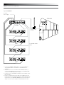
Fig. A—Connections
To 12VDC
Power Supply
1. Use the included BNC-to-BNC cables to connect the RF OUT of
each M3T Transmitter to the INPUTS of the MCB4 Antenna
Combiner.
2. Attach the antenna (one included with each M3T Transmitter), or
an optional ATW-A49S directional antenna, to the ANTENNA FEED
connector on the MCB4 Antenna Combiner.
3. If desired, connect the MCB4 DC OUTPUT to the DC INPUT of each
M3T transmitter.
4. Plug the included desktop power supply of the MCB4 into the DC
power input. The power supply is designed to operate properly from
any AC power source 100-240V, 50/60 Hz without user adjustment.
Simply connect the power supply to a standard AC power outlet.
1 INPUTS 2
3 4
OUTPUT
+12V DC
600 mA
1 2
ANTENNA FEED
MCB4
ATW-A49
M3T
M3T
M3T
M3T
3 INPUTS 4
INPUT
+12V DC
5A
Whip or Paddle
Antenna
Included BNC-to-BNC
Cables
Included DC Interconnect Cables

MCB4 Installation and Operation
POWER
ON
MCB4
ANTENNA COMB
INER SYS
TEM
440 to 865 MHz
OFF
POWER
ON
MCB4
ANTENNA COMBINER SYSTEM
440 to 865 MHz
OFF
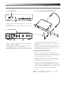
Fig. D—Front-mount Antenna–Rack Mount Hardware Kit
Antenna not included
7. The included rack-mount hardware kit (includes rack ears and
hardware) is provided to permit attachment in a standard 19" audio
equipment rack.
8. The antenna may be mounted on the front of the long rack ear. The
following parts are included in the kit: Long rack ear; short rack ear;
one BNC bulkhead connector with mounting hardware; one 34"
BNC-to-BNC cable; six rack-mount screws.
Assembling the Rack Mount Hardware Kit
• Remove the nut and lock-washer from the bulkhead connector.
Install the connector from the front into one of the two holes in the
long rack ear (see Fig. D). Note that the at on the threaded section
must be aligned with the at in the panel hole.
• Install the lock-washer and nut (included) over the back of the
bulkhead connector. Secure the connector from the back with its
lock-washer and nut, tightening the nut rmly.
• Connect one end of the provided BNC-BNC cable to the antenna
feed input jack on the back of the MCB4. Attach the other end of
the cable to the back of the BNC bulkhead connector. Make certain
the bayonet twist-ring is fully latched on the connector at both ends.
• Finally, mount the transmitter antenna to the BNC bulkhead
connector.
Note: To mount two MCB4 units side by side in a single rack space,
use Audio-Technica AT8630 Joining-plate Kit.
7
8
1 INPUTS 2
3 4
OUTPUT
+12V DC
600 mA
1 2
ANTENNA FEED 3 INPUTS 4
INPUT
+12V DC
5A
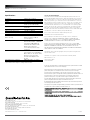
Fig. B—Front Panel Controls
1. POWER SWITCH: Press switch to apply power to unit. Press again
to turn unit off.
2. POWER INDICATOR: The indicator will light when power is applied.
Fig. C—Rear Panel Controls
3. INPUTS 1 - 4: BNC isolated transmitter antenna inputs. Maximum
RF input is +20 dBm or 100mW.
4. DC OUTPUT JACKS: Provides +12V DC (center positive) at up to
600 mA from each jack to power M3T transmitters.
5. DC POWER INPUT: 3-pin header connector for +12V DC power input.
6. ANTENNA FEED: Attachment point for a standard 50 ohm antenna.
1
3
2
64 5

MCB4 Installation and Operation
Audio-Technica U.S., Inc.
1221 Commerce Drive, Stow, Ohio 44224 USA +1 (330) 686-2600
Audio-Technica Limited
Old Lane, Leeds LS11 8AG England +44 (0) 113 277 1441
Audio-Technica (Greater China) Limited
Unit K, 9/F., Kaiser Est. (Ph.2) 51 Man Yue St. Kowloon, HK. +852-2356-9268
Audio-Technica (S.E.A.) Pte. Ltd.
No 1 Ubi View, #01-14 Focus One, Singapore 408555 +65-6749-5686
Audio-Technica Corporation
2206, Naruse Machida, Tokyo Japan
©2010 Audio-Technica U.S., Inc. audio-technica.com P52098
Specications
†
Description 4-Way Active Combiner
Bandwidth 440–865 MHz
VSWR < 1.7:1(within specied bandwidth)
System Gain (per channel) 0dB Typical
(within specied bandwidth)
Impedance 50 ohms, typical (within specied
bandwidth)
Termination Type BNC Female (5 total)
Maximum RF Input Power +20 dBm or 100 mW
Third Order Intercept Point Greater than 25 dBm
Weight 1.0 kg (2.2 lbs.)
Dimensions 210 mm (8.27") W x 176 mm
(Base unit only) (6.93") D x 46 mm (1.80") H
(one rack space)
Power Supply Desktop Switching Power Supply
Rated at 5A @ 12VDC or 60 Watts
Input Voltage 100-240VAC via
detachable IEC 320/C14 cable
Output is provided on an
overmolded 3-pin Molex style
termination
Accessories IEC 320/C14 power cable (for
power supply); 5 - 22" RF (BNC to
BNC) cables; 4 – DC power cables;
Rack kit for front-mounting
antennas and adaptation to a
19" rack
Transmitter power (optional) 600mA @ 12VDC – 4 outputs
† Specications are subject to change without notice.
U.S. Two-Year Limited Warranty
This product and selected Audio-Technica brand products purchased in the U.S.A.
from an authorized Audio-Technica (A.T.U.S.) dealer are warranted for two years from
date of purchase by A.T.U.S. to be free of defects in materials and workmanship. To
identify those products, go to www.audio-technica.com/usawarranties. In event of a
defect, End-User’s exclusive remedy is at A.T.U.S.’ election, the cost of repair, refund
of the purchase price in the form of credit or cash, or replacement of the product.
The product must be delivered to A.T.U.S. or an Authorized Service Center, prepaid,
together with the sales slip or other proof of purchase date. This warranty excludes
defects due to normal wear, abuse, shipping damage, or failure to use product in
accordance with instructions. This warranty is void in the event of unauthorized repair
or modication, or removal or defacing of the product labeling.
For U.S. service return instructions and procedure please go to:
www.audio-technica.com/returninstructions.
A.T.U.S.’ warranty is to the End User only. Except for A.T.U.S.’ said express
warranty, A.T.U.S. MAKES NO WARRANTIES, EXPRESS OR IMPLIED, WITH
RESPECT TO THE PRODUCTS. A.T.U.S. SPECIFICALLY MAKES NO WARRANTY
OF MERCHANTABILITY OR FITNESS FOR A PARTICULAR PURPOSE.
Except to the extent precluded by applicable state law, A.T.U.S. IS NOT LIABLE
FOR CONSEQUENTIAL, INCIDENTAL, DIRECT OR SPECIAL DAMAGES ARISING,
DIRECTLY OR INDIRECTLY, IN RESPECT OF SUCH PRODUCTS OR USE OR
FAILURE THEREOF, WHETHER BASED ON BREACH OF WARRANTY, NEGLIGENCE,
STRICT LIABILITY, TORT OR OTHERWISE.
This warranty gives you specic legal rights, and you may have other rights which
vary from state to state.
Outside the U.S.A., please contact your local dealer for warranty details.
Audio-Technica U.S., Inc.
1221 Commerce Drive
Stow, Ohio 44224
To reduce the environmental impact of a multi-language printed document, product information is available
online at www.audio-technica.com in a selection of languages.
An de réduire l’impact sur l’environnement de l’impression de plusieurs, les informations concernant les
produits sont disponibles sur le site www.audio-technica.com dans une large sélection de langue.
Para reducir el impacto al medioambiente, y reducir la producción de documentos en varios leguajes,
información de nuestros productos están disponibles en nuestra página del Internet: www.audio-technica.com.
Para reduzir o impacto ecológico de um documento impresso de várias linguas, a Audio-Technica
providência as informações dos seus produtos em diversas linguas na www.audio-technica.com.
Per evitare l’impatto ambientale che la stampa di questo documento determinerebbe, le informazioni sui
prodotti sono disponibili online in diverse lingue sul sito www.audio-technica.com.
Der Umwelt zuliebe nden Sie die Produktinformationen in deutscher Sprache und weiteren Sprachen auf
unserer Homepage: www.audio-technica.com.
Om de gevolgen van een gedrukte meertalige handleiding op het milieu te verkleinen, is productinformatie in
verschillende talen “on-line” beschikbaar op: www.audio-technica.com.
-
 1
1
-
 2
2
-
 3
3
-
 4
4


Audio Technica MCB4 Installation And Operation
- Taper
- Installation And Operation
dans d''autres langues
- English: Audio Technica MCB4
Documents connexes
-
Audio Technica ATW-CHG2 Manuel utilisateur
-
-
-
-
-
-
-
-