
Installation
Guide
02/16 EINS 516664
PLEASE READ THESE INSTRUCTIONS BEFORE COMMENCING SITE SURVEY
OR INSTALLING THIS APPLIANCE.
IMPORTANT : SAVE INSTRUCTIONS FOR FUTURE REFERENCE
IMPORTANT : CONSERVER CES INSTRUCTIONS POUR REFERENCE FUTURE
For use in USA/Canada
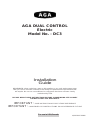
AGA DUAL CONTROL
Electric
Model No. - DC3
REMEMBER: when replacing a part on this appliance, use only replacement parts
that you can be assured conform to the safety and performance specification that
we require. Do not use reconditioned or copy parts that have not been clearly
authorized by AGA.

2
SECTION PAGE
PRODUCT SAFETY 3
GENERAL NOTES 4
DELIVERY REQUIREMENTS 4
GENERAL INSTALLATION REQUIREMENTS 4
APPLIANCE DIMENSIONS - AGA DC3 5
INSTALLATION 6 - 7
CONNECTION TO THE POWER SUPPLY - AGA DC3 8
MAINS SUPPLY LOCATION - AGA DC3 9
AGA DC3 HANDRAIL CONNECTION 10
WIRING DIAGRAM - AGA DC3 11
INSTRUCTIONS 12
CONTENTS

3
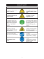
PRODUCT SAFETY
MEANING/DESCRIPTION SIGNIFICATION/DESCRIPTIONSYMBOL
WARNING/CAUTION
An appropriate safety instruction
should be followed or caution to a
potential hazard exists.
AVERTISSEMENT
Une consigne de sécurité
appropriée doivent être suivies
ou garde d’un danger potentiel
exists.
DANGEROUS VOLTAGE
To indicate hazards arising from
dangerous voltages.
TENSION DANGEREUSE
Pour indiquer les dangers
résultant des tensions
dangereuses.
PROTECTIVE EARTH (GROUND)
To identify any terminal which
is intended for connection to an
external conductor for protection
against electric shock in case
of a fault, or the terminal of
a protective earth (ground)
electrode.
TERRE DE PROTECTION
Pour marquer bornes destin
ées à
être raccordées à un conducteur
de protection extérieur contre les
chocs éclectiques en cas de
défaut d’isolement, ou pour
marquer la borne de la terre de
protection.
HEAVY
This product is heavy and
reference should be made to the
safety instructions for provisions
of lifting and moving.
LOURD
Ce produit est lourd et doit
être
fait référence auc consignes de
sécurité relatives aux dispositions
de soulever et déplacer.
DISCONNECT MAINS SUPPLY
Disconnect incoming supply
before inspection or maintenance.
APPAREIL À LASER DE
CLASSE 2
Alimentation d’entr
ée Débrancher
avant inspection ou d’entretien.
REFER TO MANUAL
Refer to relevant instructions
detailed within the product
manual.
ATTENTION, SURFACE TRÉS
CHAUDE
Reportez-vous aux instructions
applicables, indiquées dans le
manuel du produit.

4
GENERAL NOTES
NOTE: THESE INSTALLATION INSTRUCTIONS SHOULD BE LEFT WITH THE RANGE AND
THE USER TO RETAIN FOR FUTURE REFERENCE.
Before installation of an AGA can be made, the site is inspected for suitability by an authorized
AGA distributor and corrected where necessary to conform with local or regional electrical codes.
DELIVERY REQUIREMENTS
The AGA DC3 arrives on 1 pallet.
There must be access to the kitchen to manipulate a foot print of 39
9
/16” (1005mm) x 29
1
/8”
(740mm). A wooden template (skate with castor wheels) of dimensions 39
9
/16” (1005mm) x
29
1
/8” (740mm) could be used to check if the AGA Dual Control fully built appliance is able to
fit through the property grounds and doors into its installation position in the kitchen. It must
also be considered that the height of the appliance is 37
3
/4” (960mm) off pallet and 43
1
/4 ”
(1100mm) on the pallet, so high level obstacles/restrictions must not be overlooked.
GENERAL INSTALLATION REQUIREMENTS
The installation of the range must be in accordance with the relevant requirements of the local
Wiring and Building Regulations. It should be in accordance also with any relevant requirements
of the local or state codes.
In your own interest and that of safety to comply with the law, all appliances should be installed
by an authorized AGA distributor in accordance with the relevant regulations.
CAUTION:
THIS UNIT IS HEAVY, PROPER EQUIPMENT AND ADEQUATE
MANPOWER MUST BE USED IN MOVING THE RANGE TO
AVOID DAMAGE TO THE UNIT OR THE FLOOR

5
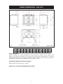
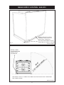
RANGE DIMENSIONS - AGA DC3
Fig. 1 DESN 516297
Range Dimensions
When surveying for a range installation the actual clearance required for the ‘body’ of the
appliance should be increased by 3/8” (10mm) beyond the figures quoted above. This allows
safe margin to take into account the natural dimensional variations found in major castings. In
particular the width across the appliance recess could be critical.
APPLIANCE WEIGHT (Excludes Packaging)
Model: AGA Dual Control (DC3) - 978 lbs
DATA PLATE LOCATED BEHIND BOTTOM PLINTH.
RH SIDE VIEW
FRONT VIEW
LH SIDE VIEW
PLAN VIEW
MINIMUM WALL POSITION
MINIMUM WALL POSITION
A B C D E F G H J K L
mm 987 951 913 680 1388 760 1145 698 116 10 634
pouces 38
7
/8 37
3
/8 35
7
/8 26
3
/4 54
5
/8 29
7
/8 45
1
/8 27
1
/2 4
9
/16
3
/8 25

6
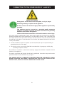
INSTALLATION
Range Base or Hearth
It is essential that the base or hearth on which the range stands should be level and be
capable of supporting the total weight of the range. The base of the built-in AGA plinth must be
level and sit above finished floor height for service access.
Plinth
The front plinth cover is removable and must not be obstructed by flooring or tiles. If necessary
the range must be raised by the thickness of the tiles to ensure the plinth can be removed.
Rear Wall
Since this appliance runs continuously, please take note of these IMPORTANT instructions:
Combustible Walls
Houses constructed of combustible materials (such as all-timber or stud wall partitions and
batoned plasterboarded walls) require special wall heat protection features.
Non-combustible material behind a range must be of at least 1” (25mm) thick insulation
board (Monolux or equivalent), up to hotplate level.
SPECIAL NOTE: Ensure electric cabling or plastic services do not pass within or on the
outside of the wall, behind or directly above the range.
This type of material can age prematurely when exposed to continuous higher
ambient temperature.
Alternatively the range can be spaced 1
1
/2” (38mm) away from the wall to create an air gap.
The air gap must be left open and NOT blocked off across the top edge.
Side Clearances
A
1
/8” (3mm) gap is required each side between the range top plate and adjoining work
surfaces that may be fitted, this is to allow for the safe removal of the top plate should this be
required at a later date.
Where ranges are to be fitted against a side wall a 4
9
/16” (116mm) side clearance is required
on the right and left hand side for oven door access.
If the AGA is to be installed in a brick recess, then the minimum clearance should be increased
by at least
3
/8” (10mm), to allow for the walls not being square.
In addition a minimum clearance of 39
3
/8” (1000mm) must be available at the front of the
range to enable the range to be serviced.
Tiling
When the range is to stand in a recess or against a wall which is to be tiled, under no
circumstances should the tiles overlap the range top plate, access to remove the hotplate must
be allowed for servicing at a later date.
A gap of at least 3/8” (10mm) must be observed between the rear of the top plate and the wall
behind the range.
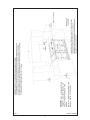
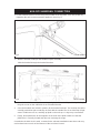
Overhead Cabinets
To eliminate the risk of burns or fires by reaching over hot surface units, cabinet storage space
located above the surface units should be avoided.

7
NOTE: ANY OVERHEAD FITTED
CABINETS MUST NOT EXCEED 13”
PROJECTED DEPTH ABOVE THE
RANGE.
DIM ‘D’ TO BE NOT LESS THAN THE
NORMAL WIDTH OF THE RANGE.
Fig. 2 DESN 516668

8
CONNECTION TO THE POWER SUPPLY - AGA DC3
Electric Shock Hazard
Rating plate is located behind removable plinth, see Fig. 4, Page 9
Electrical grounding is required on this appliance.
DO NOT connect to the electrical supply until the appliance is permanently
grounded.
This appliance must be connected to a grounded metallic permanent
supply or a grounding connector should be connected to the grounding
terminal or wire lead on the appliance.
Failure to follow these instructions could result in death or serious injury.
This range must be supplied with a 240V, 60Hz power supply and connected to an individual,
properly grounded branch circuit protected by a circuit breaker. At 240V, it has a maximum load
of 30 amps. Electric hook-up must be done by a licensed electrician. This unit must be installed
according to local codes, or in the absence of local codes, the National Electrical Code for the
country of installation.
l Product installation requires a separate (not shared) 240V/40 amp circuit protected by an
appropriate branch circuit supply.
l The service cord on your range is fitted with a standard four (4) prong type 14-50P plug
(matching receptacle 14-50R).
The method of connection to the mains electricity supply must facilitate complete electrical
isolation of the appliance.
The mains connection and isolation should not be positioned above the range and must be
positioned within the area defined in Fig. 4, Page 9.
THIS RANGE MUST BE COMPLETELY ISOLATED FROM THE ELECTRICITY SUPPLY
BEFORE SERVICING. THE RANGE IS DESIGNED FOR THE VOLTAGE STATED ON THE
RATING PLATE, WHICH IS SITUATED BEHIND THE PLINTH COVER.

9
MAINS SUPPLY LOCATION - AGA DC3
Fig. 4 DESN 516295
THE MAINS SUPPLY CONNECTION AND ISOLATION POINT MUST BE WITHIN
THE ZONE SHOWN
RATING LABEL
LOCATED BEHIND
PLINTH, PULL
TO REMOVE
Fig. 3
DESN 516643
MAINS CABLE FED FROM
CONTROL TRAY LEFT OR
RIGHT EXIT THROUGH
DUCTING DEPENDENT UPON
POSITION OF SUPPLY SOCKET

10
1. Fit the handrail bracket over the fixing stud located on the top plate. Lock into position by
tightening the grub screw nearest the appliance. (See Fig. 5).
Fig. 5 DESN 516883
AGA DC3 HANDRAIL CONNECTION
2. Next the handrail, endcaps and handrail require assembly.
Slide the handrail through the handrail brackets.
Fig. 6 DESN 516880
AGA DC3 HANDRAIL CONNECTION
3. Once the handrail assembly is located squarely, lock the handrail in position by winding in
the grub screws on the underside of each handrail bracket.
4. Once the handrails are locked in position, fit the handrail endcaps. The endcaps should be
carefully pushed into place until they sit flush with the outside face of each bracket (a light
smear of lubricant such as, washing up liquid on the end cap ‘O’ rings may ease fitment.
5. Finally, fit the plinth facia to the magnets on the front of the plinth. Make sure that the
plinth facia is centrally located and does not overhang the range.
Commission the AGA Dual Control, as stated in the relevant Installation Instructions and carry
out functional test on each of the features of the AGA Dual Control.

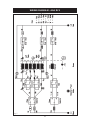
11
WIRING DIAGRAM - AGA DC3
Fig. 7

12
INSTRUCTIONS
Hand the Users Guide to the user for retention and instruct in the safe operation of the range.
Advise the user that, for continued efficient and safe operation of the range, servicing is carried
out at intervals recommended by the AGA distributor.
When replacing a part on this range, use only replacement parts that you can be assured
conform to the safety and performance specification that we require. Do not use reconditioned
or copy parts that have not been clearly authorised by AGA.

13

14

15

16
For further advice or information contact
your local AGA Specialist
With AGA Marvel’s policy of continuous product
improvement, the Company reserves the right to
change specifications and make modifications to
the appliance described and illustrated at any time
Supplied by
AGA Marvel
1260 E. Van Deinse St.
Greenville, MI, 48838
Business (616) 754-5601
Fax (616) 754-9690
Toll Free Telephone 800-223-3900
www.agamarvel.com
-
 1
1
-
 2
2
-
 3
3
-
 4
4
-
 5
5
-
 6
6
-
 7
7
-
 8
8
-
 9
9
-
 10
10
-
 11
11
-
 12
12
-
 13
13
-
 14
14
-
 15
15
-
 16
16


dans d''autres langues
- English: AGA ADC3EHEA Installation guide
Documents connexes
-
AGA TC3 Total Control Handrail Le manuel du propriétaire
-
-
-
-
-
-
-
-
-