Jenn-Air JDRP436WP02 Guide d'installation
- Catégorie
- Cuisinières
- Taper
- Guide d'installation
Ce manuel convient également à

JENN-AIR°
INSTALLATIONINSTRUCTIONS
30" (76.2 CM), 36" (91.4 CM) AND 48" (I 21.9 CM)
PRO-STYLE®DUALFUELCONVECTION RANGES
. I_STRUCTIONSD'I_STALLATION
CUISINIERESA CONVECTION A DOUBLECOMBUSTIBLE
ETDETYPECOMMERCIAL DE 30" (76,2 CM),
36" (91,4 CM) ET48" (I 21,9 CM)
TableofContents/Tabledes mati@res
RANGE SAFETY .............................................................................. 2
INSTALLATION REQUIREMENTS ................................................ 4
Tools and Parts ............................................................................ 4
Location Requirements ................................................................ 5
Electrical Requirements - U.S.A. Only ......................................... 7
Electrical Requirements - Canada Only ....................................... 8
Gas Supply Requirements ........................................................... 8
INSTALLATION INSTRUCTIONS ................................................ 10
Unpack Range ............................................................................ 10
Install Optional Backguard ......................................................... 10
Install Anti-Tip Bracket ............................................................... 11
Electrical Connection - U.S.A. Only ........................................... 12
Make Gas Connection ................................................................ 14
Verify Anti-Tip Bracket Location ................................................ 14
Level Range ................................................................................ 15
Install Griddle .............................................................................. 15
Electronic Ignition System .......................................................... 15
Reinstall Kickplate ...................................................................... 17
Complete Installation .................................................................. 17
GAS CONVERSIONS .................................................................... 18
LP Gas Conversion .................................................................... 18
Natural Gas Conversion ............................................................. 20
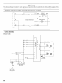
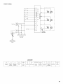
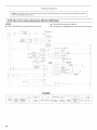
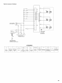
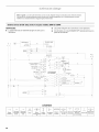
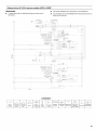
Strip Circuits ............................................................................... 22
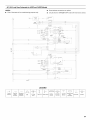
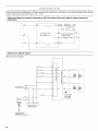
Wiring Diagrams ......................................................................... 24
SI_CURITI_ DE LA CUISINli=RE ................................................ 26
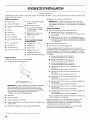
EXIGENCES D'INSTALLATION ................................................ 28
Outils et pieces ........................................................................ 28
Exigences d'emplacement ...................................................... 29
Specifications de I'installation electrique ............................... 31
Specifications de I'alimentation en gaz .................................. 32
INSTRUCTIONS D'INSTALLATION ......................................... 34
Deballage de la cuisiniere ....................................................... 34
Installation du dosseret facultatif ............................................ 34
Installation de la bride antibasculement ................................. 35
Raccordement au gaz ............................................................. 36
Verification de I'emplacement
de la bride antibasculement .................................................... 37
Reglage de I'aplomb de la cuisiniere ...................................... 37
Installation de la plaque a frire ................................................ 37
Systeme d'allumage electronique ........................................... 37
Reinstallation du garde-pieds ................................................. 39
Achever I'installation ............................................................... 39
CONVERSIONS POUR CHANGEMENT DE GAZ ................... 40
Conversion pour I'alimentation au propane ............................ 40
Conversion pour I'alimentation au gaz naturel ....................... 42
Schemas des circuits .............................................................. 44
Schemas de c&blage ............................................................... 46
IMPORTANT:
Save for local electrical inspector's use.
Installer: Leave installation instructions with the homeowner.
Homeowner: Keep installation instructions for future reference.
IMPORTANT :
A conserver pour consultation par I'inspecteur local des installations _lectriques.
Installateur : Remettre les instructions d'installation au propri_taire.
Propri6taire : Conserver les instructions d'installation pour r_f@ence ult@ieure.
W10145393A

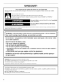
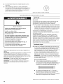
RANGESAFETY
Your safety and the safety of others are very important.
We have provided many important safety messages in this manual and on your appliance. Always read and obey all safety
messages.
This is the safety alert symbol.
This symbol alerts you to potential hazards that can kill or hurt you and others.
All safety messages will follow the safety alert symbol and either the word "DANGER" or "WARNING."
These words mean:
You can be killed or seriously injured if you don't immediately
follow instructions.
You can be killed or seriously injured if you don't follow
instructions.
All safety messages will tell you what the potential hazard is, tell you how to reduce the chance of injury, and tell you what can
happen if the instructions are not followed.
WARNING: If the information in this manual is not followed exactly, a fire or explosion
may result causing property damage, personal injury or death,
- Do not store or use gasoline or other flammable vapors and liquids in the vicinity of this
or any other appliance,
- WHAT TO DO IF YOU SMELL GAS:
• Do not try to light any appliance.
• Do not touch any electrical switch.
• Do not use any phone in your building.
• Immediately call your gas supplier from a neighbor's phone. Follow the gas supplier's
instructions.
• If you cannot reach your gas supplier, call the fire department.
- Installation and service must be performed by a qualified installer, service agency or
the gas supplier,
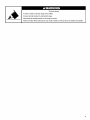
WARNING: Gas leaks cannot always be detected by smell.
Gas suppliers recommend that you use a gas detector approved by UL or CSA.
For more information, contact your gas supplier.
If a gas leak is detected, follow the "What to do if you smell gas" instructions.
In the State of Massachusetts, the following installation instructions apply:
m Installations and repairs must be performed by a qualified or licensed contractor, plumber, or gasfitter qualified or licensed by
the State of Massachusetts.
m If using a ball valve, it shall be a T-handle type.
m A flexible gas connector, when used, must not exceed 3 feet.
2

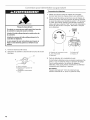
Tip Over Hazard
A child or adult can tip the range and be killed.
Connect anti=tip bracket to wall behind range.
Reconnect the anti=tip bracket, if the range is moved.
Failure to follow these instructions can result in death or serious burns to children and adults.

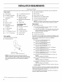
INSTALLATIONREQUIREMENTS
s csnd
Gather the required tools and parts before starting installation. Read and follow the instructions provided with any tools listed here.
Tools needed
• Tape measure
• #2 Phillips screwdriver
• 1/8"x 41¼'' flat-blade
screwdriver
• Level
• Drill
• Wrench or pliers
• Pipe wrench
• Adjustable wrench or
5/8"wrench
• 3/8"drive ratchet
• 1/8"drill bit
• 1%6"combination wrench
• 1/4",3/8",%e" nut drivers
Parts supplied
Check that all parts are included.
• Anti-tip bracket kit
• 3/le"carbide tip masonry bit
• Marker or pencil
• Pipe-joint compound
resistant to LP gas
• Noncorrosive leak-detection
solution
• Tubing cutter
For LP/Natural Gas
Conversions
• T15 Torx_t screwdriver
• 7/8"socket
• Adjustable wrench
• 1/2"deep-well socket
• 7 mm nut driver
• Masking tape
• Gas pressure regulator
• Burner grates
• Burner heads and caps
• Griddle drip tray (on griddle models)
• LP orifice package (W10221288)
• Conversion label (VV10221320)
NOTE: The cooktop is manufactured for use with Natural gas.
To convert to LP gas, see the "Gas Conversions" section.
Parts needed
• Power supply cord kit:
• 30" (76.2 cm) and 36" (91.4 cm) models - A UL listed
40 amp power supply cord kit
• 48" (121.9 cm) models - A UL listed 50 amp power supply
cord kit marked for use with nominal 13/8"(34.93 mm)
diameter connection openings
• A UL listed strain relief
• UL listed wire connectors
All models must be installed with a backguard if installing at zero
clearance to a combustible backwall. See "Cabinet Dimensions"
in the "Location Requirements" section for installation
requirements.
• 30" (76.2 cm) Adjustable Backguard
Order Part Number 8285148
• 36" (91.4 cm) Adjustable Backguard
Order Part Number 8284756
• 48" (121.9 cm) Adjustable Backguard
Order Part Number 8284755
• 9" (22.9 cm) Backguard for 30" (76.2 cm) Ranges
Order Part Number W10115773
• 9" (22.9 cm) Backguard for 36" (91.4 cm) Ranges
Order Part Number W10115776
A. Anti-tip bracket
B. #8-18 x 1" Phillips head screws (4)
NOTE: Anti-tip bracket must be securely mounted to
subfloor. Thickness of flooring may require longer screws to
anchor bracket to subfloor. Longer screws are available from
your local hardware store. See "Install Anti-Tip Bracket"
section.
9" (22.9 cm) Backguard for 48" (121.9 cm) Ranges
Order Part Number W10115777
22" (55.9 cm) Backguard with Shelf for 30" (76.2 cm)
Ranges
Order Part Number W10225950
22" (55.9 cm) Backguard with Shelf for 36" (91.4 cm)
Ranges
Order Part Number W10225949
• 22" (55.9 cm) Backguard with Shelf for 48" (121.9 cm)
Ranges
Order Part Number W10225948
To order, see the "Assistance or Service" section of the Use
and Care Guide.
Check local codes and consult gas supplier. Check existing gas
supply and electrical supply. See "Electrical Requirements" and
"Gas Supply Requirements" sections.
It is recommended that all electrical connections be made by a
licensed, qualified electrical installer.
I"®TORX is a registered trademark of Acument Intellectual Properties, LLC.

High Altitude Conversion
To convert the cooktop for elevations above 6,560 ft (1999.5 m),
order a High Altitude Conversion Kit.
• Part Number W10237848 - LP high altitude
• Part Number W10160841 - Natural gas high altitude
To order, see the "Assistance or Service" section of the Use and
Care Guide.
IMPORTANT: Observe all governing codes and ordinances. Do
not obstruct flow of combustion and ventilation air.
• It is the installer's responsibility to comply with installation
clearances specified on the model/serial rating plate. The
model/serial rating plate is located under the console on the
right-hand side.
• It is recommended that a 600 CFM or larger range hood be
installed above the range.
• It is not recommended that a microwave hood combination
be mounted above the range.
• Recessed installations must provide complete enclosure of
the sides and rear of the range.
• To eliminate the risk of burns or fire by reaching over heated
surface units, cabinet storage space located above the
surface units should be avoided. If cabinet storage is to be
provided, the risk can be reduced by installing a range hood
that projects horizontally a minimum of 5" (12.7 cm) beyond
the bottom of the cabinets.
• All openings in the wall or floor where range is to be installed
must be sealed.
• Do not seal the range to the side cabinets.
• Cabinet opening dimensions that are shown must be used.
Given dimensions are minimum clearances.
• The anti-tip bracket must be installed. To install the anti-tip
bracket shipped with the range, see "Install Anti-Tip Bracket"
section.
• Grounded electrical supply is required. See "Electrical
Requirements" section.
• Proper gas supply connection must be available. See "Gas
Supply Requirements" section.
• Contact a qualified floor covering installer to check that the
floor covering can withstand at least 200°F (93°C). Use an
insulated pad or 1¼,,(0.64 cm) plywood over carpet and under
range if installing range over carpeting.
IMPORTANT: To avoid damage to your cabinets, check with your
builder or cabinet supplier to make sure that the materials used
will not discolor, delaminate or sustain other damage. This oven
has been designed in accordance with the requirements of UL
and CSA International and complies with the maximum allowable
wood cabinet temperatures of 194°F (90°C).
Mobile Home - Additional Installation Requirements
The installation of this range must conform to the Manufactured
Home Construction and Safety Standard, Title 24 CFR, Part 3280
(formerly the Federal Standard for Mobile Home Construction
and Safety, Title 24, HUD Part 280). When such standard is not
applicable, use the Standard for Manufactured Home
Installations, ANSI A225.1/NFPA 501A or with local codes.
In Canada, the installation of this range must conform with the
current standards CAN/CSA-A240-1atest edition, or with local
codes.
Mobile home installations require:
• When this range is installed in a mobile home, it must be
secured to the floor during transit. Any method of securing
the range is adequate as long as it conforms to the standards
listed above.
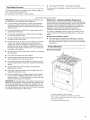
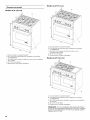
Product Dimensions
30" (76.2 cm) models
C
D
A
\
A. Optional backguard may be installed.
B. 273/4" (70.5 cm) depth with control panel, see NOTE*
C. 353/4" (89.6 cm) cooktop height when setting on the wheels
D. 30" (76.2 cm) width
E.Model/serial rating plate location

36" (91.4 cm) models
C
B
A
\
\
D
E
A. Optional backguard may be installed.
B. 27%" (68.9 cm) depth with control panel, see NOTE*
C. 353/4"(90.2 cm) cooktop height when setting on the wheels
D. 36" (91.4 cm) width
E. Model/serial rating plate location
48" (121.9 cm) models
Cabinet Dimensions
Cabinet opening dimensions shown are for 25" (64 cm)
countertop depth, 24" (61 cm) base cabinet depth and
36" (91.4 cm) countertop height. Dimensions must be met in
order to ensure a flush fit to backwall.
IMPORTANT: If installing a range hood above the range, follow
the range hood installation instructions for dimensional
clearances above the cooktop surface.
A
installation
area*
B
B
A
C
\
E
A. Optional backguard may be installed.
B. 27%" (68.9 cm) depth with control panel, see NOTE*
C. 353/4"(90.2 cm) cooktop height when setting on the wheels
D. 48" (121.9 cm) width
E. Model/serial rating plate location
*NOTE: When installed in a 24" (61.0 cm) base cabinet with
25" (63.5 cm) countertop; front of oven door protrudes
17/8'' (4.8 cm) beyond 24" (61.0 cm) base cabinet.
A. 18" (45.7 cm) upper cabinet to countertop
B. 30" (76.2 cm) model: 42" (106. 7 cm) min. upper cabinet width
36" (91.4 cm) model: 48" (121.9 cm) min. upper cabinet width
48" (121.9 cm) modeh 60" (152.4 cm) min. upper cabinet width
C. 13" (33 cm) max. upper cabinet depth
D. For minimum clearance to top of range, see NOTE**.
E. 30¼" (76.8 cm) on 30" (76.2 cm) models
36¼" (92.1 cm) on 36" (91.4 cm) models
48¼" (122.6 cm) on 48" (121.9 cm) models
F. 6" (15.2 cm) min. clearance from both sides of range to side
wall or other combustible material
G. 15" (38.1 cm)
H. 22" (55.9 cm) on 30" (76.2 cm) models
28" (71.1 cm) on 36" (91.4 cm) models
40" (101.6 cm) on 48" (121.9 cm) models
I. 1V2"(3.8 cm)
J. 3" (7.6 cm)
K. 5" (12. 7 cm)
L. 6" (15.2 cm) on 30" (76.2 cm) models
14" (35.5 cm) on 36" (91.4 cm) models
24" (61.0 cm) on 48" (121.9 cm) models
M. 10V2" (26.7cm)
N. 6" (15.2 cm)
O. 6" (15.2 cm), see NOTE***
*NOTE: Receptacle must be rotated 90° for Canadian
installation.
**NOTE: Minimum Clearances
30" (76.2 cm) models: 30" (76.2 cm) minimum clearance
between the top of the cooking platform and the bottom of an
uncovered wood or metal cabinet.
36" (91.4 cm) models: 42" (106.7 cm) minimum clearance
between the top of the cooking platform and the bottom of an
uncovered wood or metal cabinet.
6

48" (121.9 cm) models: 42" (106.7 cm) minimum clearance
between the top of the cooking platform and the bottom of an
uncovered wood or metal cabinet.
***NOTE: If backwall is constructed of a combustible material
and a backguard is not installed, a 6" (15.2 cm) minimum
clearance is required for all models.
If codes permit and a separate ground wire is used, it is
recommended that a qualified electrical installer determine that
the ground path and wire gauge are in accordance with local
codes.
If codes permit and a separate ground wire is used, it is
recommended that a qualified electrician determine that the
ground path is adequate.
Do not use an extension cord.
Be sure that the electrical connection and wire size are adequate
and in conformance with the National Electrical Code, ANSI/
NFPA 70-latest edition and all local codes and ordinances.
A copy of the above code standards can be obtained from:
National Fire Protection Association
One Batterymarch Park
Quincy, MA 02269.
WARNING: Improper connection of the equipment-grounding
conductor can result in a risk of electric shock. Check with a
qualified electrician or service technician if you are in doubt as to
whether the appliance is properly grounded. Do not modify the
power supply cord plug. If it will not fit the outlet, have a proper
outlet installed by a qualified electrician.
Electrical Connection
To properly install your range, you must determine the type of
electrical connection you will be using and follow the instructions
provided for it here.
• Range must be connected to the proper electrical voltage
and frequency as specified on the model/serial number rating
plate. The model/serial number rating plate is located under
the console on the right-hand side. Refer to the figures in the
"Product Dimensions" section of the "Location
Requirements" section.
• Use a 4-wire power supply cord rated at 250 volts,
40 or 50 amps and investigated for use with ranges.
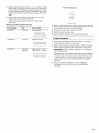
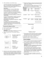
Range Rating* Specified Rating of Power
Supply Cord Kit and
Circuit Protection
120/240 Volts 120/208 Volts Amps Range Size
8.8 - 16.5 kW 7.8 - 12.5 kW 40 or 50"* 30" (76.2 cm),
36" (91.4 cm)
16.6 - 22.5 kW 12.6 - 18.5 kW 50 48" (121.9 cm)
*The NEC calculated load is less than the total connected load
listed on the model/serial rating plate.
**If connecting to a 50-amp circuit, use a 50-amp rated cord with
kit. For 50-amp rated cord kits, use kits that specify use with a
nominal 13/8"(34.9 mm) diameter connection opening.
• A circuit breaker is recommended.
If connecting to a 4-wire system:
This range is manufactured with the ground connected to the
cabinet. The ground must be revised so the green ground wire of
the 4-wire power supply cord is connected to the cabinet. See
"Electrical Connection."
Grounding through the neutral conductor is prohibited for new
branch-circuit installations (1996 NEC); mobile homes; and
recreational vehicles, or an area where local codes prohibit
grounding through the neutral conductor.
When a 4-wire receptacle of NEMA Type 14-50R is used, a
matching UL listed, 4-wire, 250-volt, 40- or 50-amp, range power
supply cord must be used. This cord contains 4 copper
conductors with ring terminals or open-end spade terminals with
upturned ends, terminating in a NEMA Type 14-50R plug on the
supply end.
The fourth (grounding) conductor must be identified by a green or
green/yellow cover and the neutral conductor by a white cover.
Cord should be Type SRD or SRDT with a UL listed strain relief
and be at least 4 ft (1.22 m) long.
4-wire receptacle (14-50R)
The minimum conductor sized for the copper 4-wire power
cord are:
40-amp circuit
2 No.-8 conductors
1 No.-10 white neutral
1 No.-8 green grounding
If connecting to a 3-wire system:
Local codes may permit the use of a UL listed, 3-wire, 250-volt,
40- or 50-amp range power supply cord (pigtail). This cord
contains 3 copper conductors with ring terminals or open-end
spade terminals with upturned ends, terminating in a NEMA Type
10-50P plug on the supply end. Connectors on the appliance end
must be provided at the point the power supply cord enters the
appliance. This uses a 3-wire receptacle of NEMA Type 10-50R.
3-wire receptacle (10-50R)
• Wire sizes and connections must conform with the rating of
the range.
• The Tech Sheet is located in the console in a clear plastic
bag.

Electrical Shock Hazard
Electrically ground range.
Failure to do so can result in death, fire, or
electrical shock.
If codes permit and a separate ground wire is used, it is
recommended that a qualified electrical installer determine that
the ground path and wire gauge are in accordance with local
codes.
Be sure that the electrical connection and wire size are adequate
and in conformance with the CSA Standard C22.1, Canadian
Electrical Code, Part 1 - latest edition, and all local codes and
ordinances.
A copy of the above code standards can be obtained from:
Canadian Standards Association
178 Rexdale Blvd.
Toronto, ON M9W 1R3 CANADA
• Check with a qualified electrical installer if you are not sure
the range is properly grounded.
• When a 4-wire, single phase 250 volt, 60 Hz., AC only
electrical supply is available, a 40-amp minimum circuit
protection is required on 30" (76.2 cm) and 36" (91.4 cm)
ranges and a 50-amp minimum circuit protections is required
on 48" (121.9 cm) ranges, fused on both sides of the line.
• A time-delay fuse or circuit breaker is recommended.
• This range is equipped with a CSA International Certified
Power Cord intended to be plugged into a standard 14-50R
wall receptacle. Be sure the wall receptacle is within reach of
range's final location.
• Do not use an extension cord.
Explosion Hazard
Use a new CSA international approved gas supply line.
install a shut=off valve.
Securely tighten all gas connections.
if connected to LP, have a qualified person make sure
gas pressure does not exceed 14" (36 cm) water
column.
Examples of a qualified person include:
licensed heating personnel,
authorized gas company personnel, and
authorized service personnel.
Failure to do so can result in death, explosion, or fire.
Observe all governing codes and ordinances.
IMPORTANT: This installation must conform with all local codes
and ordinances. In the absence of local codes, installation must
conform with American National Standard, National Fuel Gas
Code ANSI Z223.1/NFPA 54 - latest edition or CAN/CGA B149 -
latest edition.
IMPORTANT: Range cooktop must be connected to a regulated
gas supply.
IMPORTANT: Leak testing of the range cooktop must be
conducted according to the manufacturer's instructions.
Type of Gas
Natural Gas:
This range is design-certified by CSA International for use with
Natural gas or, after proper conversion, for use with LP gas.
• This range is factory set for use with Natural gas. The model/
serial rating plate located under the console on the right-hand
side has information on the types of gas that can be used. If
the types of gas listed do not include the type of gas
available, check with the local gas supplier.
LP Gas conversion:
Conversion must be done by a qualified service technician.
No attempt shall be made to convert the range cooktop from the
gas specified on the model/serial rating plate for use with a
different gas without consulting the serving gas supplier. To
convert to LP gas, use the LP gas conversion kit provided with
your range and see the "Gas Conversions" section. The parts for
this kit are in the literature package supplied with the range.
8

Gas Supply Line
• Provide a gas supply line of 3_,,(1.9 cm) rigid pipe to the
range location. A smaller size pipe on longer runs may result
in insufficient gas supply. With LP gas, piping or tubing size
can be 1/2"(1.3 cm) minimum. Usually, LP gas suppliers
determine the size and materials used in the system.
NOTE: Pipe-joint compounds that resist the action of LP gas
must be used. Do not use TEFLON ®ttape.
Flexible metal appliance connector:
• If local codes permit, a new CSA design-certified,
4 - 5 ft (122 - 152.4 cm) long, %" (1.6 cm) or
3_,,(1.9 cm) I.D., flexible metal appliance connector may
be used for connecting range to the gas supply line.
• A 1/2"(1.3 cm) male pipe thread is needed for connection
to the female pipe threads of the inlet to the range
pressure regulator.
• Do not kink or damage the flexible metal tubing when
moving the range.
Rigid pipe connection:
The rigid pipe connection requires a combination of pipe
fittings to obtain an in-line connection to the range. The rigid
pipe must be level with the range connection. All strains must
be removed from the supply and fuel lines so range will be
level and in line.
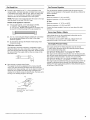
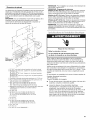
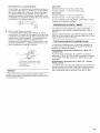
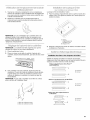
Must include a manual shutoff valve:
The supply line must be equipped with a manual shutoff
valve. This valve should be located in the same room but
external to the range opening, such as an adjacent cabinet. It
should be in a location that allows ease of opening and
closing. Do not block access to shutoff valve. The valve is for
turning on or shutting off gas to the range.
A
B
A. Gas supply fine
B. Shutoff valve "open" position
C. To range
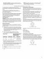
Gas Pressure Regulator
The gas pressure regulator supplied with this range must be
used. The inlet pressure to the regulator should be as follows for
proper operation:
Natural Gas:
Minimum pressure: 6" (15.2 cm) WCP
Maximum pressure: 14" (35.6 cm) WCP
LP Gas:
Minimum pressure: 11" (27.9 cm) WCP
Maximum pressure: 14" (35.6 cm) WCP
Contact local gas supplier if you are not sure about the inlet
pressure.
Burner Input Rating - Altitude
Input ratings shown on the model/serial rating plate are for
elevations up to 2,000 ft (609.6 m).
For elevations above 2,000 ft (609.6 m), ratings need to be
reduced at a rate of 4% for each 1,000 ft (304.8 m).
Gas Supply Pressure Testing
Gas supply pressure for testing regulator must be at least
1" water column pressure above the manifold pressure shown
on the model/serial rating plate.
Line pressure testing above 1/2psi gauge (14" WCP)
The range and its individual shutoff valve must be disconnected
from the gas supply piping system during any pressure testing of
that system at test pressures in excess of 1/2psi (3.5 kPa).
Line pressure testing at 1/2psi gauge (14" WCP) or lower
The range must be isolated from the gas supply piping system by
closing its individual manual shutoff valve during any pressure
testing of the gas supply piping system at test pressures equal to
or less than 1/2psi (3.5 kPa).
t®TEFLON is a registered trademark of E.I. Du Pont De Nemours and Company.

INSTALLATIONINSTRUCTIONS
Excessive Weight Hazard
Use two or more people to move and install range.
Failure to do so can result in back or other injury.
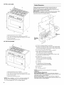
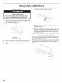
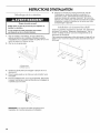
1. Remove shipping materials, tape and film from range. Keep
shipping pallet under range. Remove oven racks, grates and
parts package from inside oven.
2. Remove screws from kickplate.
A. Kickpla te
B. Remove these screws.
3. Push up on kickplate to release plate from shoulder screws.
4. Lay kickplate to the side to avoid scratching the stainless
steel.
5. For 48" (121.9 cm) models only, rotate center support
counterclockwise off the pallet until it stops.
6.
NOTE: This support is used only for shipping and is not
needed for installation.
Lay a piece of cardboard from side packing on the floor
behind range. Using 2 or more people, firmly grasp each side
of range. Lift range up about 3" (8.0 cm) and move it back
until range is off shipping pallet. Set range on cardboard to
avoid damaging floor.
All ranges may require a backguard. See "Cabinet Dimensions" in
the "Location Requirements" section. See the "Tools and Parts"
section for information on ordering.
Remove island trim and attach backguard using 6 screws, insert
3 from the front and 3 from the back (9" [22.9 cm] backguard
shown).
10

Floor Mounting
Tip Over Hazard
A child or adult can tip the range and be killed.
Connect anti=tip bracket to rear range foot.
Reconnect the anti=tip bracket, if the range is moved.
Failure to follow these instructions can result in death
or serious burns to children and adults.
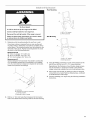
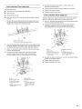
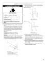
Wall Mounting
I
A
A. #12 x 1%" screws
B.Anti-tip bracket
1=
2.
Determine which mounting method to use: floor or wall.
If you have a stone or masonry floor you can use the wall
mounting method. Determine and mark the centerline of the
cutout space. The mounting bracket must be installed on the
right side of the cutout. Position mounting bracket in cutout
as shown in the following illustration.
Measurement B"
30" (76.2 cm) ranges: 11%" (29.5 cm)
36" (91.4 cm) ranges: 14%" (37.1 cm)
48" (121.9 cm) ranges: 205/8'' (52.4 cm)
Measurement C"
Optional distance from backwall. If backwall is constructed
of a combustible material and a backguard is not installed,
a 6" (15.2 cm) minimum clearance is required for all models.
Install anti-tip bracket accordingly.
C
A. Centerline
B. Centerline of cutout to centerline
of anti-tip bracket
C. Backwafl to back of range
Drill two 1/8"(3.0 mm) holes that correspond to the bracket
holes of the determined mounting method. See the following.
I
A. #12 x 1%" screws
B. Anti-tip bracket
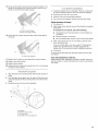
3. Using the Phillips screwdriver, mount anti-tip bracket to the
wall or floor with the two #12 x 1%" screws provided.
Depending on the thickness of your flooring, longer screws
may be necessary to anchor the bracket to the subfloor.
Longer screws are available from your local hardware store.
4. Move range close enough to opening to allow for electrical
connections to be made. Remove shipping base, cardboard
or hardboard from under range.
5. Continue installing your range using the following installation
instructions.
11

E®CF_<CC_ _.........._s__"__° _,_,_J_ _ ,,
30" (76.2 cm) and 36" (91.4 cm) Models
Electrical Shock Hazard
Disconnect power before servicing.
Use a new 40 amp power supply cord.
Plug into a grounded outlet.
Failure to follow these instructions can result in death,
fire, or electrical shock.
48" (121.9 cm) Models
Electrical Shock Hazard
Disconnect power before servicing.
Use a new 50 amp power supply cord.
Plug into a grounded outlet.
Failure to follow these instructions can result in death,
fire, or electrical shock.
1.
2.
3.
Disconnect power.
Remove the terminal block cover screws and disengage
mounting tabs to remove terminal block cover from back of
range.
C
A. Phillips head screws
B. Terminal block cover
C. Two mounting tabs at bottom
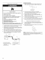
Add power supply cord strain relief.
• Assemble a UL listed strain relief in the opening.
Tighten strain relief screw against the power supply cord.
4. Complete installation following instructions for your type of
electrical connection:
4-wire (recommended)
3-wire (if 4-wire is not available)
Electrical Connection Options
If your home has: And you will be Go to Section:
connecting to:
4-wire receptacle
(NEMA type 14-50R)
A UL listed,
250-volt
minimum,
40- or 50-amp,
range power
supply cord
4-wire connection:
Power supply cord
3-wire receptacle
(NEMA type 10-50R)
A UL listed,
250-volt
minimum,
40- or 50-amp,
range power
supply cord
3-wire connection:
Power supply cord
A. UL listed strain relief
12

4-wire connection: Power supply cord
Use this method for:
New branch-circuit installations (1996 NEC)
Mobile homes
1.
Recreational vehicles
In an area where local codes prohibit grounding through the
neutral
Remove the ground-link screw from the range frame. Save
the ground-link screw. Bend the ground link away from the
range so that it does not contact the range.
\
2.
3.
4.
A.Ground-link screw
B.Ground Link bent awayfrom range
Connect the green ground wire from the power supply cord to
the range using the ground-link screw. The ground wire must
be attached first and must not contact any other terminal.
Use a %" nut driver to remove the hex washer head screws
from the terminal blocks.
Connect the neutral (center) wire to the center terminal
connector using one of the hex washer head screws.
Securely tighten screw for proper electrical connection.
E
D
F
C .....
B
/ G
O
H
5. Connect the other 2 wires (lines 1 and 2) to the outer
aluminum terminal blocks.
6. Securely tighten screws for proper electrical connection.
7. Tighten strain relief screws.
8. Replace terminal block cover.
3-wire connection: Power supply cord
Use this method only if local codes permit connecting cabinet-
ground conductor to neutral wire of power supply cord.
1. Use a 1¼,,nut driver and remove the hex washer head screws
from the aluminum terminal blocks.
2. Connect the neutral (center) wire to the center terminal
connector using one of the hex washer head screws.
Securely tighten screw for proper electrical connection.
C
A
0
F
G
A. Line 1
B. Ground Link
C. Hex washer head screw
D. Silver-colored terminal
block screw
E. Neutral (center) wire
F. Line 2
G. UL listed strain relief
and 40- or 50-amp range
power supply cord
3. Connect the other 2 wires (lines 1 and 2) to the outer terminal
screws on the terminal block.
4. Tighten strain relief screws.
5. Replace terminal block cover.
A. Line 1
B. Green ground wire
C. Ground-link screw
D. Hex washer head
screw
E. Silver-colored terminal
block screw
F. Ground Link
G. Neutral (center) wire
H. Line 2
I. UL listed strain relief
and 40- or 50-amp
range pc wer supply
cord
13

Explosion Hazard
Use a new CSA international approved gas supply line.
instal a shut-off valve.
Securely tighten all gas connections.
if connected to LP, have a qualified person make sure
gas pressure does not exceed 14" (36 cm) water
column.
Examples of a qualified person include:
licensed heating personnel,
authorized gas company personnel, and
authorized service personnel.
Failure to do so can result in death, explosion, or fire.
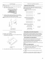
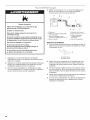
1. Assemble flexible connector from gas supply pipe to pressure
regulator located in the middle rear of the range.
2. Apply pipe-joint compound made for use with LP gas to the
smaller thread ends of the flexible connector adapters (see B
and G in the following illustration).
3. Attach one adapter to the gas pressure regulator and the
other adapter to the gas shutoff valve. Tighten both adapters.
4. Use a lS/le"combination wrench and channel lock pliers to
attach the flexible connector to the adapters. Check that
connector is not kinked.
A B C
/ /O
H G F
A. Gas pressure regulator
B. Use pipe-joint compound.
C. Adapter (must have Y2"male
pipe thread)
D. Flexible connector
E.Manual gas shutoff valve
F Y2"or 3/4"gas pipe
G. Use pipe-joint compound.
H. Adapter
Complete Connection
1. Open the manual shutoff valve in the gas supply line. The
valve is open when the handle is parallel to the gas pipe.
A. Closed valve
B. Open valve
2. Test all connections by brushing on an approved
noncorrosive leak-detection solution. If bubbles appear, a
leak is indicated. Correct any leak found.
3. Remove cooktop burner caps and grates from parts
package. Place burner caps on burner bases. Place burner
grates over burners and caps.
4. Check that the range is plugged into the appropriate outlet
(see the "Electrical Requirements" section).
5. Turn on power supply. For further information, please refer to
the user instructions located in the Use and Care Guide.
1. Turn all 4 leveling rods 1 full turn to raise the range and
provide enough clearance for the rear leveling leg to slide into
the anti-tip bracket.
2. Move range into its final location making sure rear leveling leg
slides into anti-tip bracket.
NOTE: If installing the range in a mobile home, you must secure
the range to the floor. Any method of securing the range is
adequate as long as it conforms to the standards in the "Location
Requirements" section.
14

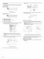
NOTE: Range must be level for satisfactory baking performance.
1. Place rack in oven.
2. Place level on rack and check levelness of the range, first
side to side; then front to back.
3. If range is not level, adjust the leveling rods. Turn leveling
rods located behind the kickplate to level range and to raise
or lower range to the desired countertop height.
NOTE: All roller feet must be off the floor upon final installation.
"_i'iiiiiii*_',4
B
A. Front leveling rod
B. Rear leveling rod
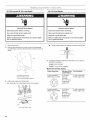
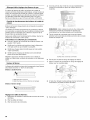
Install Burner Heads and Caps
Install the burner head, making sure the alignment pins are
properly aligned with the burner base. Place burner cap (black)
on top of the burner head.
20,000 Btu/h Ultra Power TM Dual-Flame
Burner
/_.................................................................................................................._. A.Incorrect
i................................................................................................................................
B.Correct
15,000 Btu/h Professional Burner
¢1!0c o o o o o o 00'47..................B
A. Incorrect
B. Correct
5,000 Btu/h Simmer/Melt Burner
A. Incorrect
B. Correct
e
_0 @dde s_o(ies}
The griddle is factory installed.
1. Place drip tray in the well at the front of the griddle. Slide tray
toward the back until it stops.
\\
A
\
A. Griddle drip tray
B. Griddle
2. Clean griddle before using. Refer to the Use and Care Guide.
Initial Lighting and Gas Flame Adjustments
Cooktop burners use electronic igniters in place of standing
pilots. When the cooktop control knob is turned to any position,
the system creates a spark to light the burner. This sparking
continues, until the flame is lit or the knob is turned to Off.
Check Operation of Cooktop Burners
Push in and turn each control knob to the "LITE" position.
The surface burners and grill flames should light within
4 seconds. The first time a burner is lit it may take longer than
4 seconds to light because of air in the gas line.
After verifying the proper burner operation, turn the control knobs
to OFR
If burners do not light properly:
• Turn cooktop control knob to the "OFF" position.
• Check that the range is plugged in and the circuit breaker has
not tripped or the fuse has not blown.
• Check that the gas shutoff valves are set to the "open"
position.
• Check that burner caps are properly positioned on burner
bases.
Repeat start-up. If a burner does not light at this point, contact
your dealer or authorized service company for assistance.
15


15. Lift up on the control console and set it back into place. For a
proper fit, the flange of the control console must hook over
the lip on the front of the range cooktop.
B
A. Control console flange
B.Front lip of rangecooktop
16. Check that the control console is flush with the top edge of
the range.
A
A. Flush with range top
17. Replace the 2 screws on each side of the control console.
18. Replace the control knobs.
19. Replace burner grates.
20. Test the flame by turning the control from LO to HI, checking
the flame at each setting.
1. Align shoulder screw mounting holes with shoulder screws on
range.
2. Push kickplate down against front of range until the top screw
holes are aligned with the mounting holes on the front of the
range.
3. Reattach screws to the top of the kickplate.
B
C
_o_l_©/_ IDc_ ¸ /_._/_o
1. Check that all parts are now installed. If there is an extra part,
go back through the steps to see which step was skipped.
2. Check that you have all of your tools.
3. Dispose of/recycle all packaging materials.
4. For oven use and cleaning, read the Use and Care Guide.
Check Operation of Oven(s)
1. Turn power on.
2. Start a Bake cycle. See the Use and Care Guide for operating
instructions.
If oven(s) does not operate, check the following:
• Household fuse is intact and tight; or circuit breaker has
not tripped.
• Electrical supply is connected.
• See "Troubleshooting" section in the Use and Care Guide.
3. When oven has been on for 10-15 minutes, open the oven
door, and feel for heat.
If you do not feel heat or if an error code ("F" followed by a
number plus "E" followed by a number) appears in the
display, turn off the oven and contact a qualified technician.
4. Touch OFE
To set the clock and other oven functions, refer to the Use and
Care Guide.
If you need Assistance or Service:
Please reference the "Assistance or Service" section of the Use
and Care Guide or contact the dealer from whom you purchased
your range.
A
A. Kickplate
B. Reattach these screws.
C. Top screw hole
D. Shoulder screw mounting hole
17

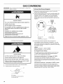
GAS CONVERSIONS
IMPORTANT: Gas conversions from Natural gas to LP gas must
be done by a qualified installer.
Explosion Hazard
Use a new CSA International approved gas supply line.
Install a shut=off valve.
Securely tighten all gas connections.
if connected to LP, have a qualified person make sure
gas pressure does not exceed 14" (36 cm) water
column.
Examples of a qualified person include:
licensed heating personnel,
authorized gas company personnel, and
authorized service personnel.
Failure to do so can result in death, explosion, or fire.
LR SC,oyf_;/olq
Tip Over Hazard
A child or adult can tip the range and be killed.
Connect anti=tip bracket to rear range foot.
Reconnect the anti=tip bracket, if the range is moved.
Failure to follow these instructions can result in death
or serious burns to children and adults.
1. Turn the manual shutoff valve to the closed position.
2. Unplug range or disconnect power.
...............................................................................S
A_
To Convert Gas Pressure Regulator
1. Remove the access cap by using a wrench, turning the
access cap counterclockwise.
2. Remove spring retainer from the cap by pushing against the
flat side of the spring retainer. Look at the spring retainer to
locate the "NAT" or "LP" position. Turn over the spring
retainer so the "LP" is showing on the bottom. Snap the
spring retainer back into the cap. Reinstall the cap onto the
regulator.
A
E D C
A. Access cap D. LP position
B. Gasket E.NAT position
C. Gas pressure regulator
3.
Test the gas pressure regulator and gas supply line.
The regulator must be checked at a minimum 1" (2.5 cm)
water column above the set pressure. The inlet pressure to
the regulator should be as follows for operation and checking
the regulator setting:
LP Gas:
Minimum pressure 11" (27.9 cm) WCP
Maximum pressure 14" (35.5 cm) WCR
Gas Supply Pressure Testing
Gas supply pressure for testing regulator must be at least
1" water column pressure above the manifold pressure
shown on the model/serial rating plate.
Line pressure testing above 1/2psi gauge (14" WOP)
The range and its individual shutoff valve must be
disconnected from the gas supply piping system during any
pressure testing of that system at test pressures in excess of
1/2psi (3.5 kPa).
Line pressure testing at 1/2psi gauge (14" WCP) or lower
The range must be isolated from the gas supply piping
system by closing its individual manual shutoff valve during
any pressure testing of the gas supply piping system at test
pressures equal to or less than 1/2psi (3.5 kPa).
A. To range
B. Shutoff valve (closed position)
C. Gas supply line
18

To Convert Surface Burners
1. If installed, remove the burner grates.
2. Remove burner cap.
3. Remove the burner head.
NOTE: A 7/8"socket must be used to remove the burner head
of the large dual burners.
4. Using a T15 Torx®screwdriver, remove the burner base.
Large Dual Burner
A. Burner cap
C B. Burner head
.......D C. Gas opening
D. Burner base
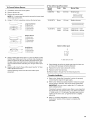
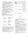
LP Gas Orifice Spud/Hood Chart
Burner Color Size Burner Style
Rating
3,000 BTU Blue 0.55 mm Small burners
r m
12,500 BTU Brass 1.04 mm
Medium burners
15,500 BTU Yellow 1.05 mm
Green 0.45 mm
Large burner - main
Large burner - simmer
Medium Burner
A. Burner cap
B. Burner head
C. Gas opening
D. Burner base
Small Burner
A. Burner cap
B. Gas opening
C. Burner base
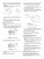
5. Apply masking tape to the end of a 7 mm nut driver to help
hold the gas orifice spud in the nut driver while changing it.
Insert nut driver into the gas opening and press down onto
the gas orifice spud and remove by turning the gas orifice
spud counterclockwise and lifting out. Set gas orifice spud
aside.
6. Replace with correct LP gas orifice spud. See the "LP Gas
Orifice Spud/Hood Chart."
Use the following chart to find the exact orifice spud
placement.
Burner orifice spud
A
x
A. Size stamp or color
7. Place Natural gas orifice in plastic parts bag for future use
and keep with package containing literature.
8. Replace the burner base using both screws.
9. Replace burner head and cap.
10. Repeat steps 2 through 9 for the remaining burners.
Complete Installation
1. Refer to the "Make Gas Connection" section for properly
connecting the range to the gas supply.
2. Refer to the "Electronic Ignition System" section for proper
burner ignition, operation, and burner flame adjustments.
IMPORTANT: You may have to adjust the "LO" setting for
each cooktop burner.
Checking for proper cooktop burner flame is very important.
The small inner cone should have a very distinct blue flame
1_,,(0.64 cm) to 1/2"(1.3 cm) long. The outer cone is not as
distinct as the inner cone. LP gas flames have a slightly
yellow tip.
3. Refer to "Complete Installation" in the "Installation
Instructions" section of this manual to complete this
procedure.
19

Tip Over Hazard
A child or adult can tip the range and be killed.
Connect anti=tip bracket to rear range foot.
Reconnect the anti=tip bracket, if the range is moved.
Failure to follow these instructions can result in death
or serious burns to children and adults.
1. Turn manual shutoff valve to the closed position.
Unplug range or disconnect power.
....................S
A__ ............... ......................C
A. Torange
B.Shutoff valve(closedposition)
C. Gassupply line
2=
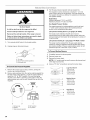
To Convert Gas Pressure Regulator
Remove the access cap by using a wrench, turning the
access cap counterclockwise.
Remove spring retainer from the cap by pushing against the
flat side of the spring retainer. Look at the spring retainer to
locate the "LP" or "NAT" position. Turn over the spring
retainer so the "NAT" is showing on the bottom. Snap the
spring retainer back into the cap. Reinstall the cap onto the
regulator.
E D
1=
2.
3=
Test the gas pressure regulator and gas supply line.
The regulator must be checked at a minimum 1" (2.5 cm)
water column above the set pressure. The inlet pressure to
the regulator should be as follows for operation and checking
the regulator setting:
Natural Gas:
Minimum pressure 6" (15.2 cm) WCP
Maximum pressure 14" (35.6 cm) WCP
Gas Supply Pressure Testing
Gas supply pressure for testing regulator must be at least
1" water column pressure above the manifold pressure
shown on the model/serial rating plate.
Line pressure testing above 1/2psi gauge (14" WCP)
The range and its individual shutoff valve must be
disconnected from the gas supply piping system during any
pressure testing of that system at test pressures in excess of
1/2psi (3.5 kPa).
Line pressure testing at 1/2psi gauge (14" WCP) or lower
The range must be isolated from the gas supply piping
system by closing its individual manual shutoff valve during
any pressure testing of the gas supply piping system at test
pressures equal to or less than 1/2psi (3.5 kPa).
To Convert Surface Burners
1. If installed, remove the burner grates.
2. Remove burner cap.
3. Remove the burner head.
NOTE: A 7/8"socket must be used to remove the burner head
of the large dual burners.
4. Using a T15 Torx_ screwdriver, remove the burner base.
Large Dual Burner
A. Burner cap
C B. Burner head
C. Gas opening
D D. Burner base
Medium Burner
A. Burner cap
B. Burner head
C. Gas opening
D. Burner base
B
Small Burner
A. Burner cap
B. Gas opening
C. Burner base
A. Access cap D. NAT position
B. Gasket E. LP position
C. Gas pressure regulator
20
La page est en cours de chargement...
La page est en cours de chargement...
La page est en cours de chargement...
La page est en cours de chargement...
La page est en cours de chargement...
La page est en cours de chargement...
La page est en cours de chargement...
La page est en cours de chargement...
La page est en cours de chargement...
La page est en cours de chargement...
La page est en cours de chargement...
La page est en cours de chargement...
La page est en cours de chargement...
La page est en cours de chargement...
La page est en cours de chargement...
La page est en cours de chargement...
La page est en cours de chargement...
La page est en cours de chargement...
La page est en cours de chargement...
La page est en cours de chargement...
La page est en cours de chargement...
La page est en cours de chargement...
La page est en cours de chargement...
La page est en cours de chargement...
La page est en cours de chargement...
La page est en cours de chargement...
La page est en cours de chargement...
La page est en cours de chargement...
-
 1
1
-
 2
2
-
 3
3
-
 4
4
-
 5
5
-
 6
6
-
 7
7
-
 8
8
-
 9
9
-
 10
10
-
 11
11
-
 12
12
-
 13
13
-
 14
14
-
 15
15
-
 16
16
-
 17
17
-
 18
18
-
 19
19
-
 20
20
-
 21
21
-
 22
22
-
 23
23
-
 24
24
-
 25
25
-
 26
26
-
 27
27
-
 28
28
-
 29
29
-
 30
30
-
 31
31
-
 32
32
-
 33
33
-
 34
34
-
 35
35
-
 36
36
-
 37
37
-
 38
38
-
 39
39
-
 40
40
-
 41
41
-
 42
42
-
 43
43
-
 44
44
-
 45
45
-
 46
46
-
 47
47
-
 48
48


Jenn-Air JDRP436WP02 Guide d'installation
- Catégorie
- Cuisinières
- Taper
- Guide d'installation
- Ce manuel convient également à
dans d''autres langues
Documents connexes
-
Jenn-Air JGRP430WP Installation Instructions Manual
-
Jenn-Air PRO-STYLE JGRP430 Manuel utilisateur
-
-
-
-
-
-
Jenn-Air JGCP436 Guide d'installation
-
-
Autres documents
-
Cosmo COS-305DFSC Manuel utilisateur
-
-
KitchenAid YKDRP707RS00 Guide d'installation
-
KitchenAid KDRS407VSS00 Guide d'installation
-
Maytag MGC8630WS00 Guide d'installation
-
-
JennAir TANKMAN50 Manuel utilisateur
-
KitchenAid W11521195A Guide d'installation
-
KitchenAid KDRS467VSS Mode d'emploi
-