Generac 3800 PSI DPW3800DMN Manuel utilisateur
- Taper
- Manuel utilisateur

Operator’s Manual for Power Washer i
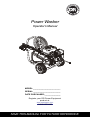
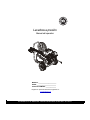
Power Washer
Operator’s Manual
SAVE THIS MANUAL FOR FUTURE REFERENCE
000263
MODEL:________________________
SERIAL:________________________
DATE PURCHASED:______________
Register your DR Power Equipment
product at:
www.activategen.com
1-888-922-8482

Table of Contents
Section 1 Introduction and Safety 1
Introduction ..................................... 1
Safety Rules .................................... 1
Safety Symbols and Meanings ........ 2
Section 2 General Information and
Setup .............................................. 3
Know Your Power Washer .............. 3
Emissions ........................................ 3
Remove Contents from Carton ....... 4
Assembly ......................................... 4
Add Engine Oil ................................ 4
Check Pump Oil .............................. 5
Fuel ................................................. 5
Water Supply ................................... 5
Connect Water Supply .................... 5
Connect Lance and High-Pressure
Hose to Spray Gun .......................... 6
Spray Gun ....................................... 6
How to Use Nozzles ........................ 6
Section 3 Operation ...................... 8
Operation and Use Questions ........ 8
Before Starting Engine .................... 8
Prepare Power Washer for Use ...... 8
Apply Detergent .............................. 9
Rinsing .......................................... 10
Clean Detergent Siphoning Tube . 10
Automatic Cool Down System
(Thermal Relief) ............................ 10
Section 4 Maintenance and
Troubleshooting ......................... 11
Maintenance ................................. 11
Maintenance Schedule ................. 11
Preventive Maintenance ............... 11
Engine Maintenance ..................... 13
Storage ......................................... 15
Troubleshooting ............................ 17
(000393a)
WARNING
CANCER AND REPRODUCTIVE HARM
www.P65Warnings.ca.gov.

Introduction and Safety
Owner’s Manual for Power Washer 1
Section 1 Introduction and Safety
Introduction
Thank you for purchasing a DR Power Equip-
ment product. This unit has been designed to
provide high-performance, efficient operation,
and years of use when maintained properly.
If any section of the manual is not understood,
contact Customer Service at 1-855-447-3734,
or
www.drpower.com with any questions or
concerns.
The owner is responsible for proper
maintenance and safe use of the equipment.
Before operating, servicing or storing this
power washer:
• Study all warnings in this manual and on
the product carefully.
• Become familiar with this manual and the
unit before use.
• Refer to the Assembly section of the
manual for instructions on final assembly
procedures. Follow the instructions
completely.
Save these instructions for future reference.
ALWAYS supply this manual to any individual
that will use this machine.
The information in this manual is accurate
based on products produced at the time of
publication. The manufacturer reserves the
right to make technical updates, corrections,
and product revisions at any time without
notice.
Safety Rules
The manufacturer cannot anticipate every
possible circumstance that might involve a
hazard. The warnings in this manual, and on
tags and decals affixed to the unit are, there-
fore, not all inclusive. If using a procedure,
work method or operating technique that the
manufacturer does not specifically recom-
mend, verify that it is safe for others. Also
make sure the procedure, work method or
operating technique utilized does not render
the equipment unsafe.
Throughout this publication, and on tags and
decals affixed to the unit, DANGER, WARN-
ING, CAUTION and NOTE blocks are used to
alert personnel to special instructions about a
particular operation that may be hazardous if
performed incorrectly or carelessly. Observe
them carefully. Their definitions are as follows:
NOTE: Notes contain additional information
important to a procedure and will be found
within the regular text of this manual.
These safety warnings cannot eliminate the
hazards that they indicate. Common sense
and strict compliance with the special instruc-
tions while performing the action or service
are essential to preventing accidents.
(000100a)
WARNING
Consult Manual. Read and understand manual
completely before using product. Failure to
completely understand manual and product
could result in death or serious injury.
(000001)
DANGER
Indicates a hazardous situation which, if not avoided,
will result in death or serious injury.
(000002)
WARNING
Indicates a hazardous situation which, if not avoided,
could result in death or serious injury.
(000003)
CAUTION
Indicates a hazardous situation which, if not avoided,
could result in minor or moderate injury.

Introduction and Safety
2 Owner’s Manual for Power Washer
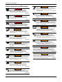
Safety Symbols and Meanings
Asphyxiation. Running engines produce
carbon monoxide, a colorless, odorless,
poisonous gas. Carbon monoxide, if not
avoided, will result in death or serious injury.
(000103)
DANGER
(000104)
DANGER
Electrocution. Water contact with a power
source, if not avoided, will result in death
or serious injury.
(000105)
DANGER
Explosion and Fire. Fuel and vapors are
extremely flammable and explosive. Add fuel
in a well ventilated area. Keep fire and spark
away. Failure to do so will result in death
or serious injury.
(000106b)
Fluid Injection. This machine produces
high-pressure fluid streams that can pierce
skin. Fluid injection could result in death or
serious injury.
WARNING
(000110)
WARNING
Risk of Fire. Hot surfaces could ignite
combustibles, resulting in fire. Fire could
result in death or serious injury.
(000101)
WARNING
Vision Loss. Eye goggles are required to be
worn when using this machine. Failure to wear
eye goggles could result in permanent
vision loss.
(000107)
WARNING
Hearing Loss. Hearing protection is
recommended when using this machine.
Failure to wear hearing protection could
result in permanant hearing loss.
(000108)
WARNING
Hot Surfaces. When operating machine, do not
touch hot surfaces. Keep machine away from
combustibles during use. Hot surfaces could
result in severe burns or fire.
(000109)
WARNING
Risk of Fire. Verify machine has properly
cooled before installing cover and storing
machine. Hot surfaces could result in fire.
(000111)
WARNING
Moving Parts. Keep clothing, hair, and
appendages away from moving parts. Failure
to do so could result in death or serious injury.
(000112)
WARNING
Risk of Falling. Use of machine creates wet
areas and trip hazards. Be aware of work area
conditions. A fall could result in death
or serious injury.
(000114)
WARNING
Risk of Falling. Do not use this machine or
any components on elevated surfaces.
Doing so can result in a fall, serious injury,
or death.
(000113)
WARNING
Recoil Hazard. Recoil could retract unexpectedl
y
if water pressure is not properly relieved from
pump, creating kickback. Kickback could result
in death or serious injury.
(000100a)
WARNING
Consult Manual. Read and understand manual
completely before using product. Failure to
completely understand manual and product
could result in death or serious injury.
(000115)
WARNING
Moving Parts. Do not wear jewelry when
starting or operating this product. Wearing
jewelry while starting or operating this product
could result in death or serious injury.
(000117c)
Personal injury. Risk of fluid injection.
Do not aim spray gun at people, animals,
electrical devices, or fragile items. Keep out
of reach of children. Failure to do so
could cause death or serious injury.
WARNING
WARNING
Environmental Hazard. Always recycle batteries at an
official recycling center in accordance with all local
laws and regulations. Failure to do so could result in
environmental damage, death or serious injury.
(000228)
(000244)
WARNING
Personal Injury / Equipment Damage. Place wand in
holster and verify that handle is locked into place
before moving. Failure to do so could result in death,
serious injury, or equipment damage.

Owner’s Manual for Power Washer 3
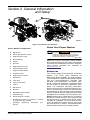
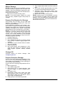
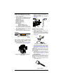
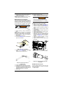
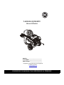
Section 2 General Information
and Setup
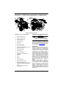
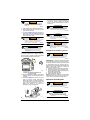
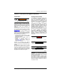
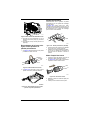
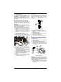
Figure 2-1.Features and Controls
Power Washer Components
Know Your Power Washer
Read this manual thoroughly before assem-
bling and operating this unit. Save this manual
for future and immediate reference. Replace-
ment owner’s manuals are available at
www.drpower.com.
Emissions
The United States Environmental Protection
Agency (US EPA) (and California Air
Resources Board (CARB), for engines/equip-
ment certified to California standards) requires
that this engine/equipment complies with
exhaust and evaporative emissions stan-
dards. Locate the emissions compliance decal
on the engine to determine applicable stan-
dards. For emissions warranty information,
please reference the included emissions war-
ranty. It is important to follow the maintenance
specifications in the manual to ensure that the
engine complies with the applicable emissions
standards for the duration of the product’s life.
NOTE: Maintenance, replacement, or repair of
emissions control devices and systems may
be performed by a small engine repair estab-
lishment or individual. To be covered by war-
ranty, all emissions control service work must
be performed by a factory authorized dealer.
See emissions warranty for further details.
000264
A
B
C
D
E
F
G
I
J
L
M
N
O
P
R
S
T
U
U
H
K
A Spray Gun
B Lance with Quick Connect
C High-Pressure Hose
D Recoil Starter
E Oil Fill
F Air Filter
G High-Pressure Pump
H Thermal Relief Valve
I Engine On/Off Switch
J Unloader Valve
K High-pressure Outlet
L Water Inlet
M Fuel Tank
N Fuel On/Off Valve
O Choke
P Belt Guard
R Nozzles
S Adjustable Side Handle
T Oil Drain Plug
U Serial Number Location.
*
Identification Label (not shown) – located
on engine blower housing
*
Detergent Siphoning Tube/Filter (not
shown)
(000100a)
WARNING
Consult Manual. Read and understand manual
completely before using product. Failure to
completely understand manual and product
could result in death or serious injury.

4 Owner’s Manual for Power Washer
Remove Contents from Carton
1. Open carton completely by cutting each
corner from top to bottom.
2. Remove and verify carton contents prior to
assembly. Carton contents should contain
one each of the following:
• Main Unit
• High-pressure Hose
• Siphon Hose & Filter
• Spray Gun
• Lance with Quick Connect Fitting
• Oil Bottle
• Parts Bag (includes):
– Owner’s Manual
– Owner’s Registration Card
– Bag of Colored Nozzles
3. Call Customer Service at 1-855-477-3734
with the unit model and serial number for
any missing carton contents.
4. Record model, serial number, and date of
purchase on front cover of this manual.
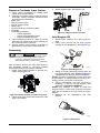
Assembly
Call Customer Service at 1-855-447-3734 for
any assembly issues or concerns. Please
have model and serial number available.
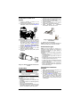
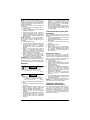
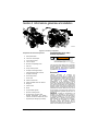
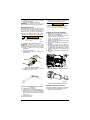
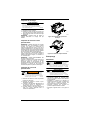
1. Insert color-coded nozzles in spaces pro-
vided. See Figure 2-2.
Figure 2-2.Insert Nozzles (number may vary)
2. Place spray gun and nozzle extension into
spray gun holder.
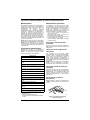
3. Attach siphon tube. See Figure 2-3.
Figure 2-3.Siphon Tube Location
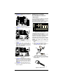
Add Engine Oil
1. Place power washer on a flat, level sur-
face.
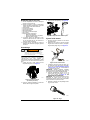
2. Clean area around oil fill and remove
orange oil fill cap/dipstick. See Figure 2-4.
Figure 2-4.Fill Engine Oil
3. Using oil funnel (optional), slowly pour oil
into oil fill opening. See Engine Oil Recom-
mendations for oil type recommendation.
NOTE: On some units there is more than one
oil fill location. In these instances it is only nec-
essary to use one of the oil fill points.
4. Check periodically until the oil level is
between "L" and "H" on the dipstick. See
Figure 2-5. DO NOT OVERFILL.
NOTE: Any attempt to crank or start the
engine before it has been properly serviced
with the recommend oil may result in engine
failure.
5. Replace oil fill cap/dipstick and fully
tighten.
Figure 2-5.Dipstick
(000100a)
WARNING
Consult Manual. Read and understand manual
completely before using product. Failure to
completely understand manual and product
could result in death or serious injury.
000265
000266
000115
000116

Owner’s Manual for Power Washer 5
Check Pump Oil
1. Place power washer on a flat, level sur-
face.
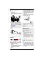
2. Clean area around oil fill and remove
vented cap/dipstick. See Figure 2-4.
Figure 2-6.Check Pump Oil
3. Check to confirm oil level is within the
markings on the dipstick. See Figure 2-5. If
oil is required, see Maintenance section.
DO NOT OVERFILL.
4. See Preventive Maintenance for additional
information.
5. Install oil dipstick until finger tight.
6. Clean up any spilled oil.
Figure 2-7.Pump Oil Dipstick
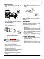
Fuel
Fuel requirements are as follows:
• Clean, fresh, unleaded gasoline.
• Minimum rating of 87 octane/87 AKI (91
RON).
• Up to 10% ethanol (gasohol) is acceptable.
• DO NOT use E85.
• DO NOT use a gas oil mix.
• DO NOT modify engine to run on alternate
fuels.Stabilize fuel prior to storage.
1. Verify unit is OFF and cooled for a mini-
mum of two minutes prior to fueling.
2. Place unit on level ground in a well venti-
lated area.
3. Clean area around fuel cap and remove
cap slowly.
4. Slowly add recommended fuel. Do not
overfill.
Figure 2-8.Add Recommended Fuel
5. Install fuel cap.
NOTE: Allow spilled fuel to evaporate before
starting unit.
Water Supply
NOTE: DO NOT run unit without sufficient
water supply. Failure to follow water supply
requirements will void unit warranty.
Water supply must meet the following require-
ments:
• DO NOT siphon standing water for the
water supply.
• Water temperature must be less than 100
°F (38 ºC).
• Water supply hose length must not exceed
50 ft (15.2 m).
• Water must be greater than 3.8 gallons per
minute (17.3 liters per minute) and no less
than 30 psi (206.8 kPa).
• DO NOT use a one-way valve, vacuum
breaker, or check valve in any part of the
water supply.
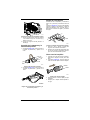
Connect Water Supply
1. Remove and discard shipping cap from
the pump water inlet.
2. Run water supply for 30 seconds prior to
connection to eliminate debris.
3. See Figure 2-9. Inspect inlet screen (A) for
debris. Clean screen or replace as neces-
sary. DO NOT run power washer if inlet
screen is damaged or missing.
000267
000268
(000105)
DANGER
Explosion and Fire. Fuel and vapors are
extremely flammable and explosive. Add fuel
in a well ventilated area. Keep fire and spark
away. Failure to do so will result in death
or serious injury.
000117

6 Owner’s Manual for Power Washer
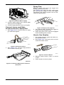
Figure 2-9.Connect Water Supply
4. Connect water supply hose to pump water
inlet (A) and hand-tighten.
5. Connect high-pressure hose to pump (B).
Connect Lance and High-
Pressure Hose to Spray Gun
1. See Figure 2-10. Connect lance to spray
gun and hand-tighten.
Figure 2-10.Connect Lance
2. See Figure 2-11. Connect high-pressure
hose to base of spray gun.
Figure 2-11.Connect High-Pressure Hose to
Spray Gun
Spray Gun
Become familiar with spray gun trigger and
locking system prior to use.
See Figure 2-12. With unit OFF, hold spray
gun and squeeze trigger to learn how trigger
mechanism and locking system can be acti-
vated and deactivated.
Figure 2-12.Spray Gun (Typical)
3. Turn ON the water, squeeze the trigger to
purge the pump system of air.
4. Verify spray gun is OFF with lock engaged
before starting power washer.
How to Use Nozzles
1. See nozzle selection guide and select cor-
rect nozzle for task.
2. See Figure 2-13. Pull back quick–connect
collar and install nozzle.
Figure 2-13.Insert Nozzle
3. Release quick-connect collar to secure
nozzle.
4. Verify nozzle is locked in place.
000270
A
B
000120
000269
00012
3
000125

Owner’s Manual for Power Washer 7
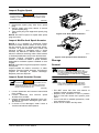
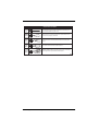
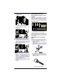
Nozzle Selection Guide
Blast
Pressure
Nozzle
(Red)
Strip
Pressure
Nozzle
(Yellow)
Clean
Pressure
Nozzle
(Green)
Wash
Pressure
Nozzle
(White)
Detergent
Nozzle
(Black)
000245
MAXIMUM - Higher pressure and lower flow for stubborn or hard to reach
surface such as second story surfaces, paint removal, oil stains, rust removal
or other stubborn substances (tar, gum, grease, wax, etc.).
MEDIUM - Higher pressure and medium flow for removing stains on hard
porous surfaces such as concrete driveways, garage floors and brick patios.
GENERAL - Medium pressure and medium flow for most all purpose cleaning
such as home siding, brick patios, wood decks, driveways and
sidewalks, garage floors, etc.
DELICATE - Lower pressure and higher flow for gentle cleaning of cars/trucks,
boats, RV’s, patio furniture, lawn equipment, etc.
DETERGENT ONLY (BLACK), Only use power washer safe detergents/soaps
to help break down stubborn dirt and grime on a variety of surfaces.

8 Owner’s Manual for Power Washer
Section 3 Operation
Operation and Use Questions
Call Customer Service at 1-855-447-3734 with
questions or concerns about unit operation
and maintenance.
Before Starting Engine
1. Verify engine oil level is correct.
2. Verify fresh fuel level is correct.
3. Verify all fittings and couplers are properly
secured.
4. Verify sufficient water supply is properly
connected.
5. Verify unit is secure on level ground, with
proper clearance and is in a well ventilated
area.
Prepare Power Washer for Use
1. Place unit on level ground, within the spec-
ified clearance required.
2. Connect appropriate water supply.
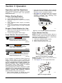
Power Washer Placement for Use
It is a violation of California Public Resource
Code, Section 4442, to use or operate the
engine on any forest-covered, brush-covered,
or grass-covered land unless the exhaust sys-
tem is equipped with a spark arrester, as
defined in Section 4442, maintained in effec-
tive working order. Other states or federal
jurisdictions may have similar laws.
Only operate power washer outdoors in a well
ventilated area. Never operate power washer
indoors, or in a confined space. Be aware of
building openings and ventilation systems
where exhaust may enter during use.
• Verify power washer is placed on level
ground to avoid tipping during operation.
• Only use the unit outdoors. Verify exhaust
gas does not enter a confined area through
windows, doors, ventilation intakes.
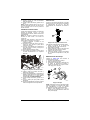
• See Figure 3-1. Keep at least 5 ft (1.5 m) of
clearance on all sides of power washer
including overhead from dwellings and
combustibles, when in use.
Figure 3-1. Five Feet of Minimum Clearance
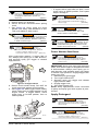
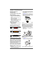
Power Washer Start-Up
NOTE: DO NOT run power washer without a
sufficient water supply turned ON. Damage to
equipment resulting from failure to follow this
instruction will void warranty.
1. Connect a sufficient water supply.
2. Move fuel valve (B) to ON.
3. Move choke lever (A) to CLOSE.
Figure 3-2. Fuel Valve and Choke
NOTE: For warm engine, verify choke lever is
in OPEN position.
4. See Figure 3-3. Turn engine switch ON.
Figure 3-3. Engine Switch
Asphyxiation. Running engines produce
carbon monoxide, a colorless, odorless,
poisonous gas. Carbon monoxide, if not
avoided, will result in death or serious injury.
(000103)
DANGER
(000110)
WARNING
Risk of Fire. Hot surfaces could ignite
combustibles, resulting in fire. Fire could
result in death or serious injury.
(000108)
WARNING
Hot Surfaces. When operating machine, do not
touch hot surfaces. Keep machine away from
combustibles during use. Hot surfaces could
result in severe burns or fire.
00027
1
000127
A
B
OFF
ON
000128

Owner’s Manual for Power Washer 9
5. Relieve spray gun pressure.
6. Secure unit from movement when pulling
recoil.
7. See Figure 3-4. Firmly grasp the recoil
handle. Pull slowly until resistance is felt.
Then pull rapidly to start engine.
After engine-start attempt, if engine fails to
run, always point spray gun in safe direction,
and squeeze spray gun trigger to release
high-pressure.
Figure 3-4. Engine Recoil
8. Return recoil handle slowly. DO NOT let
recoil snap back against recoil housing.
9. See Figure 3-5. When engine starts, slowly
move choke lever to OPEN position (A) as
engine warms. If engine falters, move
choke lever to CLOSE position, then to
OPEN position.
Figure 3-5. Fuel Valve and Choke
• If engine fails to start after six pulls, move
choke lever to OPEN position, and repeat
steps 6 through 9.
Power Washer Shut Down
IMPORTANT: Spray gun traps high-pressure
water, even when engine is stopped and water
is disconnected. Always point spray gun in
safe direction, and squeeze spray gun trigger
to release high-pressure. Engage trigger lock
when not in use.
1. Release spray gun trigger.
2. Turn engine switch OFF.
3. Squeeze spray gun trigger and release
high-pressure water.
4. Engage trigger lock.
5. Turn water supply OFF.
NOTE: Keep high-pressure hose connected
to pump and spray gun while system is pres-
surized.
Apply Detergent
(000101)
WARNING
Vision Loss. Eye goggles are required to be
worn when using this machine. Failure to wear
eye goggles could result in permanent
vision loss.
(000113)
WARNING
Recoil Hazard. Recoil could retract unexpectedl
y
if water pressure is not properly relieved from
pump, creating kickback. Kickback could result
in death or serious injury.
(000117c)
Personal injury. Risk of fluid injection.
Do not aim spray gun at people, animals,
electrical devices, or fragile items. Keep out
of reach of children. Failure to do so
could cause death or serious injury.
WARNING
000129
000127
A
(000106b)
Fluid Injection. This machine produces
high-pressure fluid streams that can pierce
skin. Fluid injection could result in death or
serious injury.
WARNING
(000110)
WARNING
Risk of Fire. Hot surfaces could ignite
combustibles, resulting in fire. Fire could
result in death or serious injury.
(000108)
WARNING
Hot Surfaces. When operating machine, do not
touch hot surfaces. Keep machine away from
combustibles during use. Hot surfaces could
result in severe burns or fire.
(000106b)
Fluid Injection. This machine produces
high-pressure fluid streams that can pierce
skin. Fluid injection could result in death or
serious injury.
WARNING
(000106b)
Fluid Injection. This machine produces
high-pressure fluid streams that can pierce
skin. Fluid injection could result in death or
serious injury.
WARNING
(000117c)
Personal injury. Risk of fluid injection.
Do not aim spray gun at people, animals,
electrical devices, or fragile items. Keep out
of reach of children. Failure to do so
could cause death or serious injury.
WARNING

10 Owner’s Manual for Power Washer
NOTE: DO NOT use caustic liquid with power
washer. Use ONLY power washer safe deter-
gents. Follow manufacturer instructions on
detergent label.
Apply detergent as follows:
1. Prepare detergent solution as required by
job.
2. Make sure siphoning tube remains fully
submerged into the detergent.
3. When inserting the siphon into a detergent
solution bottle, route the tube so as to
keep it from inadvertently contacting the
hot muffler.
4. Verify black detergent nozzle is installed.
NOTE: Detergent cannot be applied with high-
pressure nozzle (Yellow, White, Green or
Red). Only use black nozzle with detergent.
5. Start engine.
6. Firmly grasp spray gun with both hands
when using high-pressure spray to avoid
injury when spray gun kicks back.
7. Apply a high-pressure spray to a small
area and then inspect surface for damage.
If no damage is found, continue to apply
detergent.
8. Apply detergent to a dry surface, start at
lower portion of area to be washed and
work upward using long, even, overlap-
ping strokes.
IMPORTANT: Flush the detergent siphoning
system after each use. Contact an authorized
dealer or qualified service center with ques-
tions.
Rinsing
1. Remove black detergent nozzle from
lance.
2. Select and install desired high-pressure
nozzle.
3. Point spray gun in safe direction and
squeeze trigger to flush remaining deter-
gent from system.
4. Keep spray gun a safe distance from area
you plan to spray.
5. Firmly grasp spray gun with both hands
when using high-pressure spray to avoid
injury when spray gun kicks back.
6. Apply a high-pressure spray to a small
area and then inspect surface for damage.
If no damage is found, continue rinsing.
7. Start at top of area to be rinsed, working
down with same overlapping strokes as
used for cleaning.
Clean Detergent Siphoning
Tube
Flush detergent siphoning tube after each
use, before stopping the engine.
1. Place detergent siphoning tube/filter in
bucket of clean water.
2. Remove high-pressure nozzle from nozzle
extension.
3. Select and install black detergent nozzle.
4. Flush for 1-2 minutes.
5. Shut engine OFF.
6. Point spray gun in a safe direction,
squeeze spray gun trigger to release
retained high water pressure. Engage trig-
ger lock.
After Each Use
DO NOT allow water to remain in unit for long
periods of time. Sediments or minerals can
deposit on pump parts and freeze pump. Fol-
low these procedures after every use:
1. Shut engine OFF.
2. Turn water supply OFF.
3. Point spray gun in a safe direction, and
squeeze trigger to relieve trapped pres-
sure.
4. Let engine cool.
5. Disconnect hoses from spray gun and
high-pressure outlet on pump. Drain water
from hoses, spray gun, and lance. Use a
rag to wipe off components.
6. Verify engine start switch and fuel valve is
OFF.
7. Pull recoil handle approximately six times
to remove remaining liquid from pump.
8. Store unit in a clean, dry area.
NOTE: If storing for more than 30 days, see
Storage section.
Automatic Cool Down System
(Thermal Relief)
When power washer runs for 3-5 minutes
without spray gun activation, circulating water
in pump can reach temperatures above 133°F
(56.1 ºC). Thermal relief system engages to
cool pump by discharging warm water onto
ground.
(000112)
WARNING
Risk of Falling. Use of machine creates wet
areas and trip hazards. Be aware of work area
conditions. A fall could result in death
or serious injury.
(000114)
WARNING
Risk of Falling. Do not use this machine or
any components on elevated surfaces.
Doing so can result in a fall, serious injury,
or death.

Owner’s Manual for Power Washer 11
Section 4 Maintenance and Troubleshooting
Maintenance
Regular maintenance will improve perfor-
mance and extend engine/equipment life. The
manufacturer recommends that all mainte-
nance work be performed by an Independent
Authorized Service Dealer (IASD). Regular
maintenance, replacement or repair of the
emissions control devices and systems may
be performed by any repair shop or person of
the owner’s choosing. However, to obtain
emissions control warranty service free of
charge, the work must be performed by an
IASD. See the emissions warranty.
NOTE: Call Customer Service at 1-855-447-
3734 with questions about component
replacement.
NOTE: All required service and adjustments
should be each season, as detailed in mainte-
nance schedule chart.
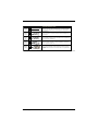
Maintenance Schedule
Follow maintenance schedule intervals,
whichever occurs first according to use.
NOTE: Adverse conditions will require more
frequent service.
Preventive Maintenance
Dirt or debris can cause improper operation
and equipment damage. Clean power washer
daily or before each use. Keep area around
and behind muffler free from combustible
debris. Inspect all cooling air openings on
power washer.
• Use a damp cloth to wipe exterior surfaces
clean.
• DO NOT insert any objects through cooling
air openings.
• Use a soft bristle brush to loosen caked on
dirt, oil, etc.
• Use a vacuum to pick up loose dirt and
debris.
Inspect and Clean Inlet Screen
Inspect inlet screen on pump water inlet.
Clean clogged screen and replace screen if
damaged.
Inspect High-Pressure Hoses
High-pressure hoses can develop leaks from
wear, kinking, or abuse. Inspect hoses before
each use. Inspect for cuts, leaks, abrasions,
bulging, and damage or movement of cou-
plings. If these conditions exist, replace hose
immediately.
NOTE: DO NOT repair high-pressure hose.
Replace with hose that meets or exceeds
maximum pressure rating of unit.
Inspect Detergent Siphoning Tube
Inspect filter on detergent tube and clean if
clogged. Tube should fit tightly on barbed fit-
ting. Examine tube for leaks or tears. Replace
filter or tube if either is damaged.
Inspect Spray Gun
NOTE: Replace spray gun immediately if it
fails any test steps.
Figure 4-1. Test Spray Gun (typical)
1. Verify spray gun hose connection is
secure.
2. Squeeze and release trigger.
First 5 Hours
Change engine oil
Every 8 Hours or Daily
Inspect/clean water inlet screen*
Inspect high-pressure hose
Inspect detergent siphoning hose/filter
Inspect spray gun and assembly for leaks
Clean debris
Inspect engine oil level
Inspect pump oil level
Every 50 Hours or Every Season
Check/clean water inlet screen**
Change pump oil**
Change engine oil**
Inspect muffler and spark arrester*
Every 100 Hours or Every Season
Service spark plug
* Clean if clogged. Replace if perforated or
torn.
** Service more often under dirty or dusty
conditions.
000123

12 Owner’s Manual for Power Washer
NOTE: Trigger should spring back into place
and lock when released.
Nozzle Maintenance
A pulsing sensation felt when squeezing spray
gun trigger may be caused by excessive
pump pressure. Typical causes of excessive
pump pressure are nozzle clog or restriction.
Immediately clean nozzle as follows:
1. Turn engine and water supply OFF.
NOTE: Keep high-pressure hose connected
to pump and spray gun while system is pres-
surized.
2. Relieve spray gun water pressure.
3. Remove nozzle from lance.
4. See Figure 4-2. Use a paper clip to remove
debris.
Figure 4-2. Remove Debris
5. See Figure 4-3. Remove lance from spray
gun and back flush thoroughly.
Figure 4-3. Back Flush Lance
6. Install nozzle on lance.
7. Install lance on spray gun.
8. Verify hose is connected to pump water
inlet, and high-pressure hose is connected
to spray gun, and pump.
9. Turn water ON.
10. Start engine.
11. Test power washer by operating with each
quick connect nozzle.
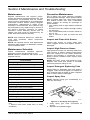
Change Pump Oil
1. Clean area around oil drain plug. See Fig-
ure 4-10.
2. Place a small pan under oil drain plug to
catch oil.
3. Remove oil drain plug. Drain oil com-
pletely.
4. Install oil drain plug. Do not over tighten.
5. Clean area around pump oil dipstick.
6. Fill pump with SAE 15W40 non-detergent
oil. Oil level must be within markings on
dipstick. See Figure 4-11. Do not overfill.
7. Install oil dipstick until finger tight.
8. Clean up any spilled oil.
Figure 4-4. Drain Pump Oil
Figure 4-5. Pump Oil Dipstick
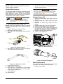
Belt Replacement
It may be necessary to replace belt if it breaks
or if there is a sudden loss of pressure:
1. Remove belt guard.
(000106b)
Fluid Injection. This machine produces
high-pressure fluid streams that can pierce
skin. Fluid injection could result in death or
serious injury.
WARNING
000109
000131
Potential of cancer. Prolonged or repeated contact
with used motor oil has been shown to cause cancer
in laboratory animals. Thoroughly wash exposed
areas with soap and water.
(000127a)
WARNING
000275
000268

Owner’s Manual for Power Washer 13
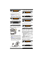
2. See Figure 4-6. Loosen nuts (A) and ten-
sioning bolt (B).
Figure 4-6. Loosen Nuts
3. See Figure 4-7. Push pump toward engine.
Figure 4-7. Push Pump Toward Engine
4. Remove old belt and install new belt.
5. See Figure 4-8. Pull pump away from
engine so bolt is approximately 2/3 of the
way through the pump bracket slot (A).
Tighten bolt.
Figure 4-8. Pull Pump Away From Engine
6. See Figure 4-6. Tighten tensioning bolt (B).
The pulleys should be aligned within 1° of
each other and the new belt should be ten-
sioned to ~90.5 lbs. (1/8” deflection under
8.3 lbs. with a tension gauge).
7. See Figure 4-6. Tighten all four nuts (A).
8. Replace belt guard before running unit.
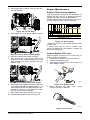
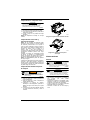
Engine Maintenance
Engine Oil Recommendations
Only high-quality detergent oils classified for
service SF, SG, SH, SJ or higher are recom-
mended. DO NOT use special additives.
Climate determines proper engine oil viscos-
ity. See chart to select correct viscosity.
Figure 4-9. Oil Viscosity
* Below 50°F (10°C) use of SAE 30 will result
in hard start.
** Above 80°F (27°C) use of 10W30 may
cause increased oil consumption. Inspect oil
level more frequently.
Inspect Engine Oil Level
Inspect engine oil level prior to each use, or
every 8 hours of operation.
1. Place power washer on a level surface.
2. Clean area around oil fill.
3. See Figure 4-10 Remove oil fill cap and
wipe dipstick clean.
Figure 4-10. Engine Oil Fill
4. Screw dipstick into filler neck. Verify
proper oil level on dipstick.
Figure 4-11. Oil Level
000272
A
B
000273
000274
A
000130
SAE 30*
5W-30
10W-30**
000115
000116

14 Owner’s Manual for Power Washer
5. Add recommended engine oil as neces-
sary.
6. Replace oil fill cap and hand-tighten.
NOTE: Some units have more than one oil fill
location. It is only necessary to use one oil fill
point.
Change Engine Oil
When using power washer under extreme,
dirty, dusty conditions, or in extremely hot
weather, change oil more frequently.
NOTE: Don’t pollute. Conserve resources.
Return used oil to collection centers.
Change oil while engine is still warm from run-
ning, as follows:
1. Place power washer on a level surface.
2. Disconnect the spark plug wire from the
spark plug and place the wire where it
cannot contact spark plug.
3. Clean area around oil fill, and oil drain
plug.
4. Remove oil fill cap.
5. Remove oil drain plug and drain oil com-
pletely into a suitable container.
Figure 4-12. Oil Drain Plug
6. Install oil drain plug and tighten securely.
7. Slowly pour oil into oil fill opening until oil
level is between “L” and “H” marks on dip-
stick. DO NOT OVERFILL.
8. Install oil fill cap, and finger tighten.
9. Wipe up any spilled oil.
10. Properly dispose of oil in accordance with
all applicable regulations.
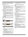
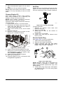
Air Filter
Engine will not run properly and may be dam-
aged if run with a dirty air filter. Service air fil-
ter more frequently in dirty or dusty conditions.
Figure 4-13. Air Filter Assembly
To service air filter:
1. Release air cleaner cover latch and
remove cover (A).
2. Remove air filter (B).
3. Gently tap air filter on flat surface to
remove dirt.
4. Install clean, or new filter.
5. Install cover and snap air cleaner cover
latch to close.
Service Spark Plug
See Figure 4-14. To service spark plug:
1. Clean area around spark plug.
2. Remove and inspect spark plug.
3. Inspect electrode gap with wire feeler
gauge and reset spark plug gap (A) to
0.028 - 0.031 in (0.70 - 0.80 mm).
Figure 4-14. Spark Plug
NOTE: Replace spark plug if electrodes are
pitted, burned or porcelain is cracked. Use
ONLY recommended replacement plug. See
Specifications.
4. Install spark plug finger tight, and tighten
an additional 3/8 to 1/2 turn using spark
plug wrench (B).
00027
6
000277
A
B
000134a
B
A

Owner’s Manual for Power Washer 15
Inspect Engine Spark
1. Disconnect spark plug wire from spark
plug.
2. Secure spark plug wire where it cannot
contact spark plug.
3. Test spark plug with approved spark plug
tester.
NOTE: DO NOT inspect for spark with spark
plug removed.
Inspect Muffler And Spark Arrester
NOTE: It is a violation of California Public
Resource Code, Section 4442, to use or oper-
ate the engine on any forest-covered, brush-
covered, or grass-covered land unless the
exhaust system is equipped with a spark
arrester, as defined in Section 4442, main-
tained in effective working order. Other states
or federal jurisdictions may have similar laws.
Contact original equipment manufacturer,
retailer, or dealer to obtain a spark arrester
designed for exhaust system installed on this
engine.
NOTE: Use ONLY original equipment replace-
ment parts.
Inspect muffler for cracks, corrosion, or other
damage. Remove spark arrester, if equipped,
inspect for damage or carbon blockage.
Replace parts as required.
Inspect Spark Arrester Screen
1. Loosen fasteners and remove heat shield
from muffler.
2. Loosen fasteners and remove spark
arrester from muffler.
3. Inspect spark arrester. Replace if torn, per-
forated or otherwise damaged (part num-
ber 0K1851).
4. If screen is not damaged, clean it with a
commercial solvent and replace.
Figure 4-15. Heat Shield Fasteners
Figure 4-16. Spark Arrestor Fasteners
Storage
General
• DO NOT store fuel from one season to
another unless properly treated.
• Replace fuel container if rust is present.
Rust in fuel will cause fuel system prob-
lems.
• Cover unit with a suitable protective, mois-
ture resistant cover.
• Store unit in a clean and dry area.
(000102)
WARNING
Accidental Start-up. Disconnect spark plug wire when
working on unit. Failure to do so could result in death
or serious injury.
(000108)
WARNING
Hot Surfaces. When operating machine, do not
touch hot surfaces. Keep machine away from
combustibles during use. Hot surfaces could
result in severe burns or fire.
000135
000136
(000105)
DANGER
Explosion and Fire. Fuel and vapors are
extremely flammable and explosive. Add fuel
in a well ventilated area. Keep fire and spark
away. Failure to do so will result in death
or serious injury.
(000109)
WARNING
Risk of Fire. Verify machine has properly
cooled before installing cover and storing
machine. Hot surfaces could result in fire.

16 Owner’s Manual for Power Washer
Winter Storage
NOTE: If pump saver is not available, connect
a 3-foot section of garden hose to water inlet
adapter. Pour RV-antifreeze (antifreeze with-
out alcohol) into hose. Pull recoil handle twice.
Disconnect 3-foot hose.
• Store unit in a clean and dry area.
NOTE: If not using power washer for more
than 30 days, prepare engine and pump for
storage.
Prepare Fuel System for Storage
Fuel stored over 30 days can go bad and
damage fuel system components. Keep fuel
fresh, use fuel stabilizer.
If fuel stabilizer is added to fuel system, pre-
pare and run engine and pump for long term
storage. Run engine for 2 minutes to circulate
stabilizer throughout fuel system. Adequately
prepared fuel can be stored up to 24 months.
NOTE: If fuel has not been treated with fuel
stabilizer, it must be drained into an approved
container. Run engine until it stops from lack
of fuel. Use of fuel stabilizer in fuel storage
container is recommended to keep fuel fresh.
Prepare Engine for Storage
1. Change engine oil.
2. Remove spark plug.
3. Pour tablespoon (5-10cc) of clean engine
oil or spray a suitable fogging agent into
cylinder.
4. Pull starter recoil several times to distrib-
ute oil in cylinder.
5. Install spark plug.
6. Pull recoil slowly until resistance is felt.
This will close valves so moisture cannot
enter engine cylinder. Gently release
recoil.
Change Oil
Change engine oil before storage. See
Change Engine Oil.
Prepare Pump for Storage
Protect unit from freezing temperatures. Fail-
ure to do so will permanently damage pump
and render unit inoperable. Freeze damage is
not covered under warranty.
Protect unit from freezing temperatures as fol-
lows:
1. Shut engine OFF.
2. Turn water supply OFF.
3. Point spray gun in a safe direction, and
squeeze trigger to relieve trapped pres-
sure.
4. Let engine cool.
5. Disconnect hoses from spray gun and
high-pressure outlet on pump. Drain water
from hoses, spray gun, and lance. Use a
rag to wipe off components.
6. Empty pump of all remaining liquids.
7. Turn engine start switch and fuel valve to
OFF.
8. Pull recoil handle approximately six times
to remove remaining liquid from pump.
9. Winterize pump with pump saver. This
minimizes freeze damage and lubricates
pistons and seals.
10. Store unit in a clean and dry area.
NOTE: If pump saver is not available, connect
a 3-foot section of garden hose to water inlet
adapter. Pour RV-antifreeze (antifreeze with-
out alcohol) into hose. Pull recoil handle twice.
Disconnect 3-foot hose.

Owner’s Manual for Power Washer 17
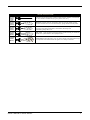
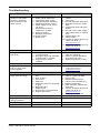
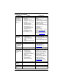
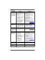
Troubleshooting
PROBLEM CAUSE CORRECTION
Pump fails to produce
pressure, has erratic
pressure, chattering,
loss of pressure, low
water volume.
1. Low pressure nozzle installed.
2. Water inlet is obstructed.
3. Inadequate water supply.
4. Inlet hose kinked or leaking.
5. Clogged hose inlet screen.
6. Water supply is over 100 ºF
(37.8 ºC).
7. High-pressure hose is
obstructed, or leaks.
8. Spray gun leaks.
9. Nozzle is obstructed.
10. Pump is faulty.
11. Belt is worn.
1. Replace with high-pressure
nozzle.
2. Clean inlet.
3. Provide adequate water flow.
4. Straighten inlet hose, patch
leak.
5. Inspect and clean inlet hose
screen.
6. Provide cooler water supply.
7. Clear obstructions or replace
hose.
8. Replace spray gun.
9. Clean nozzle.
10. Contact Customer Service at
1-855-447-3734, or
www.drpower.com.
11. Contact Customer Service at
1-855-447-3734, or
www.drpower.com.
Detergent fails to mix
with spray.
1. Detergent siphoning tube is
not submerged.
2. Detergent siphoning tube/filter
is obstructed or cracked.
3. High-pressure nozzle
installed.
1. Insert detergent siphoning
tube into detergent.
2. Clean or replace filter/deter-
gent siphoning tube.
3. Install low-pressure nozzle.
Engine runs well at no-
load, but bogs when
load is applied.
1. Engine speed too low. 1. Contact Customer Service at
1-855-447-3734, or
www.drpower.com.
Engine will not start, or
starts and runs rough.
1. Low oil level, “Oil Alert Sys-
tem”.
2. Dirty air filter.
3. Out of fuel
4. Stale fuel.
5. Spark plug wire not connected
to plug.
6. Bad spark plug.
7. Water in fuel.
8. Excessively rich fuel mixture.
9. Engine switch OFF.
1. Fill crankcase to proper level.
2. Clean or replace air filter.
3. Fill fuel tank.
4. Replace with fresh fuel.
5. Connect wire to spark plug.
6. Replace spark plug.
7. Drain fuel tank, replace with
fresh fuel.
8. Contact Customer Service at
1-855-447-3734, or
www.drpower.com.
9. Turn engine switch ON.
Engine shuts down
during operation/
1. 1. Out of fuel. 1. 1. Fill fuel tank.
Engine lacks power. 1. 1. Dirty air filter. 1. 1. Replace air filter.

Part No. 10000021246 Rev. B 11/16/2018
©2018 DR Power Equipment
All rights reserved
Specifications are subject to change without notice.
No reproduction allowed in any form without prior
written consent from DR Power Equipment
75 Meigs Road
Post Office Box 25
Vergennes, Vermont 05491
1-855-447-3734
www.drpower.com
La page est en cours de chargement...
La page est en cours de chargement...
La page est en cours de chargement...
La page est en cours de chargement...
La page est en cours de chargement...
La page est en cours de chargement...
La page est en cours de chargement...
La page est en cours de chargement...
La page est en cours de chargement...
La page est en cours de chargement...
La page est en cours de chargement...
La page est en cours de chargement...
La page est en cours de chargement...
La page est en cours de chargement...
La page est en cours de chargement...
La page est en cours de chargement...
La page est en cours de chargement...
La page est en cours de chargement...
La page est en cours de chargement...
La page est en cours de chargement...
La page est en cours de chargement...
La page est en cours de chargement...
La page est en cours de chargement...
La page est en cours de chargement...
La page est en cours de chargement...
La page est en cours de chargement...
La page est en cours de chargement...
La page est en cours de chargement...
La page est en cours de chargement...
La page est en cours de chargement...
La page est en cours de chargement...
La page est en cours de chargement...
La page est en cours de chargement...
La page est en cours de chargement...
La page est en cours de chargement...
La page est en cours de chargement...
La page est en cours de chargement...
La page est en cours de chargement...
La page est en cours de chargement...
La page est en cours de chargement...
-
 1
1
-
 2
2
-
 3
3
-
 4
4
-
 5
5
-
 6
6
-
 7
7
-
 8
8
-
 9
9
-
 10
10
-
 11
11
-
 12
12
-
 13
13
-
 14
14
-
 15
15
-
 16
16
-
 17
17
-
 18
18
-
 19
19
-
 20
20
-
 21
21
-
 22
22
-
 23
23
-
 24
24
-
 25
25
-
 26
26
-
 27
27
-
 28
28
-
 29
29
-
 30
30
-
 31
31
-
 32
32
-
 33
33
-
 34
34
-
 35
35
-
 36
36
-
 37
37
-
 38
38
-
 39
39
-
 40
40
-
 41
41
-
 42
42
-
 43
43
-
 44
44
-
 45
45
-
 46
46
-
 47
47
-
 48
48
-
 49
49
-
 50
50
-
 51
51
-
 52
52
-
 53
53
-
 54
54
-
 55
55
-
 56
56
-
 57
57
-
 58
58
-
 59
59
-
 60
60


