Victor Single- and Two-Stage Regulators Manuel utilisateur
- Taper
- Manuel utilisateur

Issue Date: December 3, 2012
Revision: JForm No.: 0056-1625
English
Canadien Français
Americas Español
Safety and Operating Instructions
Single- and Two-Stage Regulators
For Standard and Edge
™
Series Regulators
VictorTechnologies.com

WE APPRECIATE YOUR BUSINESS!
Congratulations on your new Victor
®
product. We are proud to have you as our customer
and will strive to provide you with the best service and reliability in the industry. This
product is backed by our extensive warranty and worldwide service network. To
locate your nearest distributor or service agency, please contact a representative at
the address and phone number in your area listed on the inside back cover of this
manual, or visit us on the web at www.victorequip.com.
This Operating Manual has been designed to instruct you on the correct use and
operation of your Victor
®
product. Your satisfaction with this product and its safe
operation is our ultimate concern. Therefore, please take the time to read the entire
manual, especially the Safety Precautions. They will help you to avoid potential hazards
that may exist when working with this product.
YOU ARE IN GOOD COMPANY!
The Brand of Choice for Contractors and Fabricators Worldwide.
Victor
®
is a Global Brand of gas equipment products for Victor Technologies
International, Inc. We manufacture and supply to major welding and cutting industry
sectors worldwide, including: Manufacturing, Construction, Mining, Automotive,
Aerospace, Engineering, Rural and DIY/Hobbyist, Scrap, Demolitions and Shipyards.
We distinguish ourselves from our competition through market-leading, dependable
products that have stood the test of time. We pride ourselves on technical innovation,
competitive prices, excellent delivery, superior customer service and technical support,
together with excellence in sales and marketing expertise.
Above all, we are committed to develop technologically advanced products to achieve
a safer working environment within the welding industry.

i
WARNING
Read and understand this entire manual and your employer’s safety practices
before installing, operating, or servicing the equipment. While the information
contained in this manual represents the Manufacturer’s judgment, the
Manufacturer assumes no liability for its use.
Single- and Two-Stage Regulators
Safety and Operating Instructions
Part Number 0056-1625
Published by:
Victor Technologies International, Inc.
2800 Airport Rd.
Denton, TX. 76208
(940) 566-2000
www.victorequip.com
U.S. Customer Care: (800) 426-1888
International Customer Care: (940) 381-1212
Copyright © 2011, 2012 Victor Technologies International, Inc. All rights reserved.
Reproduction of this work, in whole or in part, without written permission of the publisher is
prohibited.
The publisher does not assume and hereby disclaims any liability to any party for any
loss or damage caused by any error or omission in this manual, whether such error
results from negligence, accident, or any other cause.
Publication Date: January 20, 2011
Revision Date: December 3, 2012
Record the following information for Warranty purposes:
Where Purchased: _______________________________________________
Purchase Date: _________________________________________________
Equipment Serial #: ______________________________________________

ii
Table of Contents
SECTION 1: INTRODUCTION ...........................................1-1
SECTION 2: GENERAL SAFETY INFORMATION ...............2-3
2.01 Fire Prevention ..........................................2-3
2.02 Housekeeping ............................................2-4
2.03 Ventilation ................................................2-4
2.04 Personal Protection ..................................2-4
2.05 Compressed Gas Cylinders ......................2-5
SECTION 3: REGULATORS: SAFETY AND OPERATION ....3-7
3.01 Standard Regulators .................................3-7
3.02 Edge Series Regulators ...........................3-11
3.03 Leak Testing the System .........................3-15
SECTION 4: WHEN YOU FINISH USING THE REGULATOR 4-16
4.01 Storage ...................................................4-16
SECTION 5: STATEMENT OF WARRANTY ......................5-17

1-1
SECTION 1:
INTRODUCTION
This booklet is a guide to the safe and efficient operation of
regulators used in oxy-fuel applications. If the apparatus is not
used in an oxy-fuel application, the operator must still follow
safety and operating procedures that apply. Regulator usage
presents several potential hazards. Read this booklet thoroughly
and carefully before operating this equipment.
All operations should conform to applicable Federal, State,
County, or City regulations for installation, operation, ventilation,
fire prevention, and protection of personnel. ANSI Standard
Z49.1, “Safety in Welding and Cutting” contains detailed safety
instructions. It is available from the American Welding Society,
P.O. Box 351040, Miami, FL 33135.
A system of notes, cautions, and warnings emphasize impor tant
safety and operating information in this booklet:
NOTE
Conveys installation, operation, or maintenance information
which is important but not hazard-related.
CAUTION
Caution indicates a potentially hazardous situation which,
if not avoided, may result in injury.
WARNING
WARNING indicates a potentially hazardous situation which,
if not avoided, could result in death or serious injury.

2-2
WARNING
This product contains chemicals, including lead, or
otherwise produces chemicals known to the State of
California to cause birth defects and other reproductive
harm. Wash hands after handling.
WARNING
DO NOT attempt to use this apparatus until you thoroughly
read and understand all safety and operating instructions
provided. For your safety, practice the safety and operating
procedures described in this booklet every time you use the
apparatus. Deviating from these procedures may result in
fire, explosion, property damage and/or operator injury. If
at any time the apparatus you are using does not perform
in its usual manner, or you have any difficulty in the use of
the apparatus, STOP using it immediately. DO NOT use the
apparatus until the problem has been corrected!
WARNING
Service or repair of apparatus should be performed only
by a qualified repair technician capable of servicing gas
apparatus in strict accordance to applicable Part and Service
bulletins for Victor
®
manufactured prod ucts. Improper
service repair, or modification of the product could result in
damage to the product or injury to the operator. Improper
service repair, USE OF NON-GENUINE VICTOR
®
PARTS,
or modification could result in damage to the product or
injury to the operator.

2-3
SECTION 2:
GENERAL SAFETY INFORMATION
Read and understand all safety and operating instructions provided
before using this apparatus. RETAIN THESE INSTRUC TIONS IN A
READILY AVAILABLE LOCATION FOR FUTURE REFERENCE.
2.01 FIRE PREVENTION
Welding and cutting operations use fire or combustion as a basic
tool. The process is very useful when properly controlled. However,
it can be extremely destructive if not performed cor rectly in the
proper environment.
1. The work area must have a fireproof floor.
2. Work benches or tables used during welding or cutting
operations must have fireproof tops.
3. Use heat resistant shields or other approved material to protect
nearby walls or unprotected flooring from sparks and hot metal.
4. Keep an approved fire extinguisher of the proper size and type
in the work area. Inspect it regularly to ensure that it is in proper
working order. Know how to use the fire extin guisher.
5. Move combustible materials away from the work site. If you
can not move them, protect them with fireproof covers.
WARNING
NEVER perform welding, heating, or cutting operations
on a container that has held toxic, combustible or flammable
liq uids, or vapors. NEVER perform welding, heating, or
cutting operations in an area containing combustible vapors,
flam mable liquids, or explosive dust.

2-4
2.02 HOUSEKEEPING
WARNING
NEVER allow oxygen to contact grease, oil, or other flam-
mable substances. Although oxygen by itself will not burn,
these substances become highly explosive. They can ignite
and burn violently in the presence of oxygen.
Keep ALL apparatus clean and free of grease, oil and other
flammable substances.
2.03 VENTILATION
WARNING
Ade quately ventilate welding, heating, and cutting work
areas to prevent accumulation of explosive or toxic concen-
trations of gases. Certain combinations of metals, coatings,
and gases generate toxic fumes. Use respiratory protection
equipment in these circumstances. When welding/brazing,
read and understand the Material Safety Data Sheet for the
welding/brazing alloy.
2.04 PERSONAL PROTECTION
Gas flames produce infrared radiation which may have a harm ful
effect on the skin and especially on the eyes. Select goggles or a
mask with tempered lenses, shaded 4 or darker, to protect your
eyes from injury and provide good visibility of the work.
Always wear protective gloves and flame-resistant clothing to protect
skin and clothing from sparks and slag. Keep collars, sleeves, and
pockets buttoned. DO NOT roll up sleeves or cuff pants.
When working in a non-welding or cutting environment, always
wear suitable eye protection or face shield.

2-5
WARNING
Practice the following safety and operation precautions
EVERY TIME you use pressure regulation equipment.
Deviation from the following safety and operation
instructions can result in fire, explosion, damage to
equipment, or injury to the operator.
2.05 COMPRESSED GAS CYLINDERS
The Department of Transportation (DOT) approves the design and
manufacture of cylinders that contain gases used for welding or
cutting operations.
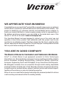
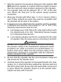
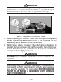
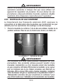
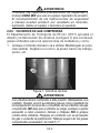
1. Place the cylinder (Figure 1) where you will use it. Keep the
cylinder in a vertical position. Secure it to a cart, wall, work bench,
post, etc.
Figure 1: Gas Cylinders
WARNING
Cylinders are highly pressurized. Handle with care. Serious
accidents can result from improper handling or mis use of
compressed gas cylinders DO NOT drop the cylinder, knock
it over, or expose it to excessive heat, flames or sparks.
DO NOT strike it against other cylinders. Contact your gas
supplier or refer to CGA P-1 “Safe Handling of Compressed
Gases in Containers” publication.

3-6
NOTE
CGA P-1 publication is available by writing the Compressed
Gas Association, 4221 Walney Road, 5th Floor, Chantilly,VA
20151-2923
2. Place the valve protection cap on the cylinder whenever mov ing
it, placing it in storage, or not using it. Never drag or roll cylinders
in any way. Use a suitable hand truck to move cylin ders.
3. Store empty cylinders away from full cylinders. Mark them
“EMPTY” and close the cylinder valve.
4. NEVER use compressed gas cylinders without a pressure
reducing regulator attached to the cylinder valve.
5. Inspect the cylinder valve for oil, grease, and damaged parts.
WARNING
DO NOT use the cylinder if you find oil, grease or
damaged parts. Inform your gas supplier of this condition
immediately.
6. Momentarily open and close (called “cracking”) the cylinder valve
to dislodge any dust or dirt that may be present in the valve.
CAUTION
Open the cylinder valve slightly. If you open the valve too
much, the cylinder could tip over. When cracking the cylinder
valve, DO NOT stand directly in front of the cylinder valve.
Always perform cracking in a well ventilated area. If an
acetylene cylinder sprays a mist when cracked, let it stand
for 15 minutes. Then, try to crack the cylinder valve again.
If this problem persists, contact your gas supplier.

3-7
SECTION 3:
REGULATORS: SAFETY AND OPERATION
NOTE
For Edge Series regulators go to section 3.02
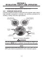
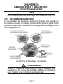
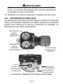
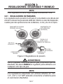
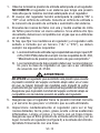
3.01 STANDARD REGULATORS
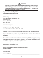
Pressure regulators (Figure 2) attached to the cylinder valve reduce
high cylinder pressures to suitable low working pressures for
welding, cutting, and other applications.
LOW PRESSURE
GAUGE (DELIVERY)
HIGH PRESSURE
GAUGE (SUPPLY)
PRESSURE
ADJUSTING
SCREW
OUTLET
CONNECTION
RELIEF
VALVE
INLET
CONNECTION
INLET
FILTER
Figure 2: Pressure Regulator
WARNING
Use the regulator for the gas and pressure for which it is
designed. NEVER alter a regulator for use with any other gas.
NOTE
Regulators purchased with open 1/8”, 1/4”, 3/8”, or 1/2”
NPT ports must be assembled to their intended system.

3-8
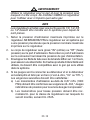
1. Note the maximum inlet pressure stamped on the regulator. DO
NOT attach the regulator to a system that has a higher pressure
than the maximum rated pressure stamped on the regulator.
2. The regulator body will be stamped “IN” or “HP” at the inlet
port. Attach the inlet port to the system supply pressure
connection.
3. Wrap pipe threads with Teflon tape 1 1/2 to 2 turns to effect a
seal. If other sealants are used, they must be compatible with
the gas that will be used in the system.
4. If gauges are to be attached to the regulator and the regu lator
is stamped and listed by a third party (i.e. “UL” or “ETL”). The
following requirements must be met:
a) Inlet gauges over 1000 PSIG (6.87 mPa) shall conform with
the requirements of UL 404, “Indicating Pressure Gauges
for Compressed Gas Service.”
b) Low pressure gauges must be UL recognized for the class
of regulator they are being used on according to UL252A.
WARNING
DO NOT use a regulator that delivers pressure exceeding
the pressure rating of the downstream equipment unless
pro visions are made to prevent over-pressurization (i.e.
system relief valve). Make sure the pressure rating of the
down stream equipment is compatible with the maximum
delivery pressure of the regulator.
5. Be sure that the regulator has the correct pressure rating and
gas service for the cylinder used.
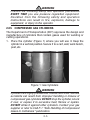
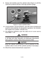
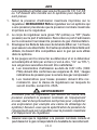
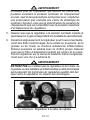
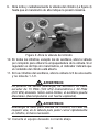
6. Carefully inspect the regulator for damaged threads, dirt, dust,
grease, oil, or other flammable substances. Remove dust and
dirt with a clean cloth. Be sure the inlet swivel filter is clean and
in place. Attach the regulator (Figure 3) to the cylinder valve.
Tighten securely with a wrench.

3-9
WARNING
DO NOT attach or use the regulator if oil, grease, flamma ble
substances or damage is present! Have a qualified repair
technician clean the regulator or repair any damage.
Figure 3: Regulator to Cylinder Valve
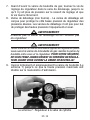
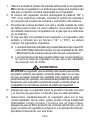
7. Before opening the cylinder valve, turn the regulator adjusting
screw counterclockwise until there is no pressure on the
adjusting spring and the screw turns freely.
8. Relief Valve (where provided): The relief valve is designed to
protect the low pressure side of the regulator from high pres-
sures. Relief valves are not intended to protect down stream
equipment from high pressures.
WARNING
DO NOT tamper with the relief valve or remove it from the
regulator.
WARNING
Stand to the side of the cylinder opposite the regulator when
opening the cylinder valve. Keep the cylinder valve between
you and the regulator. For your safety, NEVER STAND IN
FRONT OF OR BEHIND A REGULATOR WHEN OPENING
THE CYLINDER VALVE!

3-10
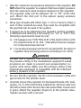
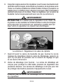
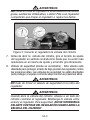
9. Slowly and carefully open the cylinder valve (Figure 4) until the
maximum pressure shows on the high pressure gauge.
Figure 4: Open Cylinder Valve
10. On all cylinders, except acetylene, open the valve completely to
seal the valve packing. On gaugeless regulators, the indicator
will register the cylinder contents only.
11. On acetylene cylinders, open the valve 3/4 of a turn and no
more than 1-1/2.
WARNING
Acetylene delivery pressure must not exceed 15 PSIG (103 kPa)
or 30 PSIG (207 kPa). Acetylene can dissociate (decompose
with explosive violence) above these pressure limits.
CAUTION
Keep the cylinder valve wrench, if one is required, on the
cylinder valve to turn off the cylinder quickly, if necessary.
12. Attach the desired downstream equipment.

3-11
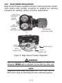
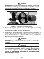
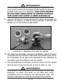
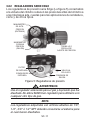
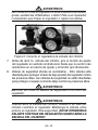
3.02 EDGE SERIES REGULATORS
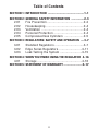
Edge Series Pressure regulators (Figure 5) attached to the cylinder
valve reduce high cylinder pressures to suitable low working
pressures for welding, cutting, and other applications.
HIGH
PRESSURE
GAUGE
(SUPPLY)
LOW
PRESSURE
GAUGE
(DELIVERY)
PRESSURE
ADJUSTING KNOB
OUTLET
CONNECTION
RELIEF VALVE
INLET
CONNECTION
INLET
FILTER
Figure 5: Edge Series Pressure Regulator
WARNING
Use the regulator for the gas and pressure for which it is
designed. NEVER alter a regulator for use with any other gas.
NOTE
Regulators purchased with open 1/8”, 1/4”, 3/8”, or 1/2”
NPT ports must be assembled to their intended system.

3-12
1. Note the maximum inlet pressure stamped on the regulator. DO
NOT attach the regulator to a system that has a higher pressure
than the maximum rated pressure stamped on the regulator.
2. The regulator body will be stamped “IN” or “HP” at the inlet
port. Attach the inlet port to the system supply pressure
connection.
3. Wrap pipe threads with Teflon tape 1 1/2 to 2 turns to effect a
seal. If other sealants are used, they must be compatible with
the gas that will be used in the system.
4. If gauges are to be attached to the regulator and the regu lator
is stamped and listed by a third party (i.e. “UL” or “ETL”). The
following requirements must be met:
a) Inlet gauges over 1000 PSIG (6.87 mPa) shall conform with
the requirements of UL 404, “Indicating Pressure Gauges
for Compressed Gas Service.”
b) Low pressure gauges must be UL recognized for the class of
regulator they are being used on according to UL 252A.
WARNING
DO NOT use a regulator that delivers pressure exceeding
the pressure rating of the downstream equipment unless
pro visions are made to prevent over-pressurization (i.e.
system relief valve). Make sure the pressure rating of the
down stream equipment is compatible with the maximum
delivery pressure of the regulator.
5. Be sure that the regulator has the correct pressure rating and
gas service for the cylinder used.
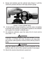
6. Carefully inspect the regulator for damaged threads, dirt, dust,
grease, oil, or other flammable substances. Remove dust and
dirt with a clean cloth. Be sure the inlet swivel filter is clean and
in place. Attach the regulator (Figure 6) to the cylinder valve.
Tighten securely with a wrench.

3-13
WARNING
DO NOT attach or use the regulator if oil, grease, flamma ble
substances or damage is present! Have a qualified repair
technician clean the regulator or repair any damage.
Figure 6: Regulator to Cylinder Valve
7. Before opening the cylinder valve, turn the regulator adjusting
knob counterclockwise until there is no pressure on the
adjusting spring and the knob turns freely.
8. Relief Valve (where provided): The relief valve is designed to
protect the low pressure side of the regulator from high pres-
sures. Relief valves are not intended to protect down stream
equipment from high pressures.
WARNING
DO NOT tamper with the relief valve or remove it from the
regulator.
WARNING
Stand to the side of the cylinder opposite the regulator when
opening the cylinder valve. Keep the cylinder valve between
you and the regulator. For your safety, NEVER STAND IN
FRONT OF OR BEHIND A REGULATOR WHEN OPENING
THE CYLINDER VALVE!

3-14
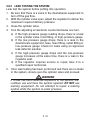
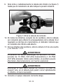
9. Slowly and carefully open the cylinder valve (Figure 7) until the
maximum pressure shows on the high pressure gauge.
Figure 7: Open Cylinder Valve
10. On all cylinders, except acetylene, open the valve completely
to seal the valve packing. On gaugeless regulators, the indicator
will register the cylinder contents open.
11. On acetylene cylinders, open the valve 3/4 of a turn and no
more than 1-1/2.
WARNING
Acetylene delivery pressure must not exceed 15 PSIG
(103 kPa) or 30 PSIG (207 kPa). Acetylene can dissociate
(decompose with explosive violence) above these pressure
limits.
CAUTION
Keep the cylinder valve wrench, if one is required, on the
cylinder valve to turn off the cylinder quickly, if necessary.
12. Attach the desired downstream equipment.

3-15
3.03 LEAK TESTING THE SYSTEM
Leak test the system before putting into operation.
1. Be sure that there is a valve in the downstream equipment to
turn off the gas flow.
2. With the cylinder valve open, adjust the regulator to deliver the
maximum required delivery pressure.
3. Close the cylinder valve.
4. Turn the adjusting screw/knob counterclockwise one turn.
a) If the high-pressure gauge reading drops, there is a leak
in the cylinder valve, inlet fitting, or high-pressure gauge.
b) If the low-pressure gauge drops, there is a leak in the
down stream equipment, hose, hose fitting, outlet fitting or
low-pressure gauge. Check for leaks using an approved
leak detector solution.
c) If the high-pressure gauge drops and the low-pressure
gauge increases at the same time, there is a leak in the
regulator seat.
d) If the regulator requires service or repair, take it to a
qualified repair technician.
5. Once leak testing has been performed and there are no leaks
in the system, slowly open the cylinder valve and proceed.
WARNING
If a leak has been detected anywhere in the system, dis-
continue use and have the system repaired. DO NOT use
leaking equipment. Do not attempt to repair a leaking
system while the system is under pressure.

4-16
SECTION 4:
WHEN YOU FINISH USING THE REGULATOR
1. Close the cylinder valve.
2. Open the valve on the downstream equipment. This drains all
pressure from the system.
3. Close the valve on the downstream equipment.
4. Turn the adjusting screw counterclockwise to release the ten-
sion on the adjusting spring.
5. Check the gauges after a few minutes for verification that the
cylinder valve is closed completely.
4.01 STORAGE
When the regulator is not in use and has been removed from the
cylinder, it should be stored in an area where it will be pro tected
from dust, oil, and grease. The inlet and outlet should be capped
to protect against internal contamination and prevent insects
from nesting.
La page est en cours de chargement...
La page est en cours de chargement...
La page est en cours de chargement...
La page est en cours de chargement...
La page est en cours de chargement...
La page est en cours de chargement...
La page est en cours de chargement...
La page est en cours de chargement...
La page est en cours de chargement...
La page est en cours de chargement...
La page est en cours de chargement...
La page est en cours de chargement...
La page est en cours de chargement...
La page est en cours de chargement...
La page est en cours de chargement...
La page est en cours de chargement...
La page est en cours de chargement...
La page est en cours de chargement...
La page est en cours de chargement...
La page est en cours de chargement...
La page est en cours de chargement...
La page est en cours de chargement...
La page est en cours de chargement...
La page est en cours de chargement...
La page est en cours de chargement...
La page est en cours de chargement...
La page est en cours de chargement...
La page est en cours de chargement...
La page est en cours de chargement...
La page est en cours de chargement...
La page est en cours de chargement...
La page est en cours de chargement...
La page est en cours de chargement...
La page est en cours de chargement...
La page est en cours de chargement...
La page est en cours de chargement...
La page est en cours de chargement...
La page est en cours de chargement...
La page est en cours de chargement...
La page est en cours de chargement...
La page est en cours de chargement...
La page est en cours de chargement...
La page est en cours de chargement...
La page est en cours de chargement...
La page est en cours de chargement...
La page est en cours de chargement...
La page est en cours de chargement...
La page est en cours de chargement...
-
 1
1
-
 2
2
-
 3
3
-
 4
4
-
 5
5
-
 6
6
-
 7
7
-
 8
8
-
 9
9
-
 10
10
-
 11
11
-
 12
12
-
 13
13
-
 14
14
-
 15
15
-
 16
16
-
 17
17
-
 18
18
-
 19
19
-
 20
20
-
 21
21
-
 22
22
-
 23
23
-
 24
24
-
 25
25
-
 26
26
-
 27
27
-
 28
28
-
 29
29
-
 30
30
-
 31
31
-
 32
32
-
 33
33
-
 34
34
-
 35
35
-
 36
36
-
 37
37
-
 38
38
-
 39
39
-
 40
40
-
 41
41
-
 42
42
-
 43
43
-
 44
44
-
 45
45
-
 46
46
-
 47
47
-
 48
48
-
 49
49
-
 50
50
-
 51
51
-
 52
52
-
 53
53
-
 54
54
-
 55
55
-
 56
56
-
 57
57
-
 58
58
-
 59
59
-
 60
60
-
 61
61
-
 62
62
-
 63
63
-
 64
64
-
 65
65
-
 66
66
-
 67
67
-
 68
68


Victor Single- and Two-Stage Regulators Manuel utilisateur
- Taper
- Manuel utilisateur
dans d''autres langues
Documents connexes
Autres documents
-
 Tweco FABRICATOR® 181i 3-IN-1 Multi Process Welding Systems Manuel utilisateur
-
ESAB FABRICATOR® 211i 3-IN-1 Multi Process Welding Systems Manuel utilisateur
-
-
 Tweco FABRICATOR® 211i 3-IN-1 Multi Process Welding Systems Manuel utilisateur
-
-
 Thermal Arc 161 STL ® Inverter Arc Welder Manuel utilisateur
-
ESAB Firepower MST 140i 3-IN-1 Multi Process Welding System Manuel utilisateur
-
-
 Tweco FABRICATOR® 141i 3-IN-1 Multi Process Welding Systems Manuel utilisateur
-


