Johnson Controls WRZ-7860-0 Installation Instructions Manual
- Taper
- Installation Instructions Manual

WRZ-7860-0 Receiver for One-to-One Wireless Room Sensing Systems
Installation Instructions
1
Refer to the QuickLIT website for the most up-to-date version of this document.
Applications
The WRZ-7860-0 Receiver for One-to-One Wireless Room Sensing Systems is designed to receive wireless Radio
Frequency (RF) temperature and humidity data from WRZ Series Wireless Room Sensors, and to provide single
zone control data to specified Metasys® system digital controllers in building HVAC systems. The WRZ Series
Wireless Room Sensor and WRZ-7860-0 Receiver combination is a functional equivalent to a network sensor,
such as an NS-BTP7001-0, but eliminates communications wiring (that is usually placed inside the wall) between
the room sensor and receiver.
Like a network sensor, the WRZ-7860-0 Receiver is designed to communicate over a Sensor Actuator (SA) Bus
interface via Master-Slave/Token-Passing (MS/TP) BACnet® protocol with Johnson Controls® Variable Air Volume
(VAV) Modular Assembly (VMA) 16 Series Controllers and Field Equipment Controllers (FECs). The receiver
supplies the sensed zone temperature and humidity, temperature setpoint, and occupancy override data.
In a typical application, one WRZ Series Wireless Room Sensor reports to one WRZ-7860-0 Receiver; however, up
to five WRZ Series Wireless Room Sensors can be associated with a single WRZ-7860-0 Receiver. In multi-sensor
applications, the receiver passes all the room sensors’ data to the controller. The VMA16 Series Controller or FEC
can be configured to either average the room sensors’ temperature and humidity input, or select the highest or
lowest sensed temperature and humidity for control of the target zone.
The WRZ-7860-0 Receiver uses direct-sequence, spread-spectrum RF technology, and operates on the 2.4 GHz
Industrial, Scientific, and Medical (ISM) band. The receiver meets the IEEE 802.15.4 standard for low power, low
duty cycle RF transmitting systems. A WRZ-7860-0 Receiver operates as a transceiver, to create a bidirectional
association with a WRZ Series Wireless Room Sensor.
Refer to the WRZ-7860-0 Receiver for One-to-One Wireless Room Sensing Systems Technical Bulletin
(LIT-12011641) for information on commissioning the WRZ-7860-0 Receiver and configuring One-to-One wireless
room sensing systems.
IMPORTANT: The WRZ-7860 Receiver is intended to provide an input to equipment under normal operating
conditions. Where failure or malfunction of the receiver could lead to personal injury or property damage to the
controlled equipment or other property, additional precautions must be designed into the control system.
Incorporate and maintain other devices, such as supervisory or alarm systems or safety or limit controls,
intended to warn of or protect against failure or malfunction of the WRZ-7860 Receiver.
IMPORTANT : Le WRZ-7860 Receiver est destiné à transmettre des données entrantes à un équipement dans
des conditions normales de fonctionnement. Lorsqu'une défaillance ou un dysfonctionnement du receiver risque
de provoquer des blessures ou d'endommager l'équipement contrôlé ou un autre équipement, la conception du
système de contrôle doit intégrer des dispositifs de protection supplémentaires. Veiller dans ce cas à intégrer de
façon permanente d'autres dispositifs, tels que des systèmes de supervision ou d'alarme, ou des dispositifs de
sécurité ou de limitation, ayant une fonction d'avertissement ou de protection en cas de défaillance ou de
dysfonctionnement du WRZ-7860 Receiver.
WRZ-7860-0 Receiver for One-to-One Wireless Room
Sensing Systems
Installation Instructions
WRZ-7860-0
Part No. 24-10563-47, Rev. E
Issued January 2017
24- 10563-47, Rev. E

WRZ-7860-0 Receiver for One-to-One Wireless Room Sensing Systems Installation Instructions
2
North American Emissions Compliance
United States
Canada
Installation
Follow these guidelines:
• Transport the WRZ-7860-0 Receiver in the original container to avoid vibration and shock damage to the
receiver.
• Verify that all the parts shipped with the receiver.
• Do not drop the receiver or subject it to physical shock.
Use the following procedure to mount, wire, and prepare the receiver for operation:
1. Mount the mounting base. See Mounting
.
2. Set the DIP switches. See Setup and Adjustments
.
3. Align the tabs on the edge of the mounting base with the slots on the edge of the receiver housing, and rotate
the assembly onto its mounting base as illustrated in Figure 3.
4. Use a 1/16 in. (1.5 mm) Allen wrench or Johnson Controls T-4000-119 Allen-Head Adjustment Tool to tighten
the tamper-resistant set screw and fasten the receiver enclosure to the mounting base.
Note: To avoid damaging the unit, do not overtighten the set screw.
5. Connect the SA Bus cable from the controller to the WRZ-7860-0 Receiver. See Wiring
.
Parts Included
The following parts are included:
• one WRZ-7860-0 Receiver with double-sided adhesive foam tape factory-installed on the back of the unit
• one installation instructions sheet
Compliance Statement (Part 15.19)
This device complies with Part 15 of the FCC Rules. Operation is subject to the following two conditions:
1. This device may not cause harmful interference, and
2. This device must accept any interference received, including interference that may cause undesired
operation.
Warning (Part 15.21)
Changes or modifications not expressly approved by the party responsible for compliance could void the user’s
authority to operate the equipment.
Industry Canada Statement(s)
The term IC before the certification/registration number only signifies that the Industry Canada technical
specifications were met.
Le terme « IC » précédant le numéro d'accréditation/inscription signifie simplement que le produit est conforme
aux spécifications techniques d'Industry Canada.

WRZ-7860-0 Receiver for One-to-One Wireless Room Sensing Systems Installation Instructions
3
Dimensions
Mounting
Location Considerations
Follow these guidelines when locating a WRZ-7860-0 Receiver:
• Locate the receiver so that it is easily accessible within the proximity of the field controller, typically on a VAV
duct, or just above or just below the ceiling tiles.
Note: Communication cables of various lengths are available to connect the receiver SA Bus; see Table 3 for
more details.
• Locate the receiver up to 100 ft (30 m) from the WRZ Series Wireless Room Sensor in a typical building
environment.
• Locate the receiver near the center of the associated room sensor layout in multi-sensor applications.
• Locate the receiver on the same floor or building level as the associated room sensor.
• Locate the receiver in the direct line-of-sight with the room sensor whenever possible. Signal transmission is
best if the path between the room sensor and receiver is as direct as possible. Line-of-sight is desirable but not
required, as long as the path is not blocked by large metal objects.
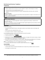
• Mount the receiver so that the antenna symbol (shown on the cover near the LEDs) is in a vertical orientation,
up or down. The antenna symbol indicates the approximate location of the receiver’s internal onboard antenna.
• If the receiver is mounted on duct work, such as a VAV box, ideally the antenna portion of the receiver
(approximately 1/3 of the enclosure) should hang below the duct work. Avoid having pipes, duct work, or other
metal obstructions in the direct line-of-sight to the room sensor.
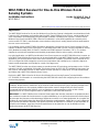
Figure 1: WRZ-7860-0 Receiver Physical
Features and Dimensions, in./mm
Tamper Resistant
Set Screw
Back of Base to
Front of Dome
1-1/2
38
FIG:wrz_7860_dmnsns
S
A
R
F
Status Light-Emitting
Diodes (LEDs)
RJ-12 Port for SA Bus
Connection (on Underside)
3-5/32
80
3-5/32
80
Figure 2: Correct Mounting Orientation
FIG:wrz_7850_mntng_orntn
S
A
R
F
S
A
R
F

WRZ-7860-0 Receiver for One-to-One Wireless Room Sensing Systems Installation Instructions
4
• Avoid large metal obstructions (including equipment rooms and elevator shafts) and concrete or brick walls
between the receiver and the room sensor.
• Do not mount the receiver in recessed areas or shelving units.
Wireless Signal Transmission Considerations
Line-of-sight transmission ranges between a WRZ Series Wireless Room Sensor and a WRZ-7860-0 Receiver can
be less than the maximum distances shown in Table 1. The effective transmission range for indoor applications
varies because of RF signal absorption and reflection due to metal obstructions, walls (or floors), and furniture
found in typical building interiors.
Test the RF signal strength between an installed room sensor and receiver by using the manual occupancy
override button on the WRZ Series Wireless Room Sensor. Refer to the WRZ-7860-0 Receiver for One-to-One
Wireless Room Sensing Systems Technical Bulletin (LIT-12011641) for more information on determining the signal
strength between a WRZ Series Wireless Room Sensor and a WRZ-7860-0 Receiver. If the RF signal path
provides unsatisfactory results, a Johnson Controls ZFR18xx Series Wireless Field Bus Router can be used as a
repeater by locating it between the room sensor and the receiver.
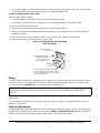
Surface Mounting the Base with Double-Sided Adhesive Foam Tape
The WRZ-7860-0 Receiver can be surface mounted using the double-sided adhesive foam tape factory-installed
on the back of the unit.
To mount the receiver base using adhesive foam tape:
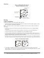
1. Remove the receiver housing from its mounting base as illustrated in Figure 3.
2. Peel off the protective paper from the adhesive foam tape on the back side of the mounting base.
Table 1: Indoor Line-of-Sight Transmission Ranges
Range Type Transmission Distance
Practical Average 100 ft (30 m)
Maximum 150 ft (45 m)
Figure 3: Removing the Receiver Housing from
Its Mounting Base
1. Loosen (but do not remove)
the tamper-resistant set screw
on the locking tab of the
mounting base.
2. Insert a coin into the slot
on the top of the receiver
housing, and depress the
locking tab on the mounting
base to release the housing.
3. Swing the
receiver
housing off
the mounting
base.
Mounting
Base
Tabs
Receiver
Housing
4. Pull the bottom of the housing
down and off the tabs on the mounting base.
receiver
FIG:wrz_7860_cvr_rmvl

WRZ-7860-0 Receiver for One-to-One Wireless Room Sensing Systems Installation Instructions
5
3. Be sure that the base is oriented in the preferred mounting position (note where the set screw is because that
is the antenna side) and press the base firmly onto the clean mounting surface.
Surface Mounting the Base with Screws
Mount the WRZ-7860-0 Receiver:
• to a wall, using two or more wall anchor molly bolts (furnished in the field)
• to a metal duct, such as a VAV box, using two or more sheet metal screws (furnished in the field)
To mount the receiver base using screws:
1. Remove the receiver housing from its mounting base as illustrated in Figure 3.
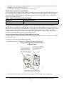
2. Use the mounting base as a template and mark the location for the screw holes on the mounting surface as
illustrated in Figure 4.
3. Drill a pilot hole at each of the marked locations. If mounting to a wall, install the molly anchors.
4. Secure the mounting base to the surface with the screws.
Wiring
The WRZ-7860-0 Receiver has a modular jack on the edge of the enclosure, opposite the side having the tamper-
resistant set screw. This modular jack for the SA Bus requires a straight-through, One-to-One connection cable
(not a crossover) to the SENSOR jack on a VMA16 Series Controller or FEC.
Note: The SA Bus cable supplies power to the WRZ-7860-0 Receiver when the VMA16 Series Controller or FEC
is powered on.
For more details on wiring the MS/TP Communication Bus, refer to the MS/TP Communications Bus Technical
Bulletin (LIT-12011034).
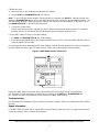
Setup and Adjustments
Before reinstalling the WRZ-7860-0 Receiver to its mounting base, set the DIP switches (Figure 5) according to the
job plans. When setting the DIP switches, be sure that the AREA and TRANSMITTER I.D. switches on the WRZ-
7860-0 Receiver and the WRZ Series Wireless Room Sensor are set to the same value.
IMPORTANT: Configure the field controller as if connected to a wired network sensor. Configuring the field
controller for use with a WRZ Series Wireless Room Sensor causes incompatibility with the WRZ-7860-0
Receiver.
Figure 4: Mounting the Receiver’s Mounting
Base with Screws
FIG:wrz_7860_mntng_bs
Tamper-Resistant
Set Screw
Mounting
Screws
Use the mounting base as
a template for locating
the screw holes on
the mounting surface.
Use any two holes that hold the base
firmly and evenly to the mounting surface.
(
Seven mounting screw holes are available
on the mounting base.)

WRZ-7860-0 Receiver for One-to-One Wireless Room Sensing Systems Installation Instructions
6
Follow these steps:
1. Disconnect the SA Bus cable before setting the DIP switches.
2. Set the AREA and TRANSMITTER I.D. DIP switches.
Note: To use a ZFR18xx Series Wireless Field Bus Router as a repeater, the AREA DIP switches and the most
significant TRANSMITTER I.D. bit (128) on the WRZ-7860-0 Receiver must all be set to the OFF (0) position. The
ZFR18xx Series Wireless Field Bus Router DIP switches are then set to the same address as the lower 7 bits of
the TRANSMITTER I.D. on the WRZ-7860-0 Receiver.
3. Connect the SA Bus cable.
Five seconds after the power is applied, the red LED flashes to indicate the firmware revision. For example,
firmware revision 3 is indicated by the LED flashing three times during the startup process.
For each WRZ-7860-0 Receiver, record the following:
•the AREA and TRANSMITTER I.D. DIP switch settings
• the location and/or identification of the controller (VMA16 Series or FEC) to which the WRZ-7860-0 Receiver is
connected by the SA Bus cable
Use this information when adjusting the DIP switch settings of the WRZ Series Wireless Room Sensor assigned to
the WRZ-7860-0 Receiver, and to associate the room sensor and receiver with the correct controller.
Refer to the WRZ-7860-0 Receiver for One-to-One Wireless Room Sensing Systems Technical Bulletin
(LIT-12011641) for more information on determining the settings for the AREA and TRANSMITTER I.D.
DIP switches for a WRZ Series Wireless Room Sensor and a WRZ-7860 Receiver.
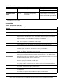
Troubleshooting
Use the Status LEDs illustrated in Figure 1 with the information included in Table 2 to troubleshoot the WRZ-7860-0
Receiver.
Repair Information
If The WRZ-7860-0 Receiver fails to operate within its specifications, replace the unit. For a replacement receiver,
contact the nearest Johnson Controls representative.
Figure 5: WRZ-7860-0 Receiver (Back View)
BATT
TRANSMITTER
I.D.
AREA
ONON
1
1
2
2
4
4
8
8
16
32
64
128
RJ-12 Port for SA Bus Connection
FIG:wrz_7860_bck_vw

WRZ-7860-0 Receiver for One-to-One Wireless Room Sensing Systems Installation Instructions
7
Accessories
Table 2: Status LEDs
Name Color Normal Descriptions
SA (Sensor Actuator)
Bus
Green Flickering Flickering = SA Bus Activity
Off Steady = No SA Bus Activity
RF (Wireless Signal
Strength and Power
Status)
Green/Red
Bi-color
Green – On
(Blinks Signal Strength Every
60 Seconds
1
)
Green = Good Room Sensor Battery
1 Blink = Marginal RF Signal Strength
2 Blinks = Good RF Signal Strength
3 Blinks = Excellent RF Signal Strength
Red = Weak Room Sensor Battery
1. Pressing the occupancy override button on the associated WRZ Series Wireless Room Sensor causes the RF LED on the
WRZ-7860-0 Receiver to blink.
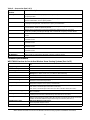
Table 3: Accessories (Part 1 of 2)
Product Code
Number
Product Description
WRZ-MHN0100-0
Wireless Room Temperature and Humidity Sensor with Passive Infrared (PIR) Occupancy
Sensor, Battery Level/Signal Strength LED, Manual Occupancy Override Button, and No Display
WRZ-MNN0100-0 Wireless Room Sensor (No Temperature or Humidity Sensing) with PIR Occupancy Sensor,
Battery Level/Signal Strength LED, Manual Occupancy Override Button, and No Display
WRZ-MTB0100-0 Wireless Room Temperature Sensor with PIR Occupancy Sensor, Display, Setpoint Dial
Adjustment Scale: 55 to 80°F (13 to 27°C), °F/°C Button, Manual Occupancy Override Button
WRZ-MTJ0100-0 Wireless Room Temperature Sensor with PIR Occupancy Sensor, Display, Up/Down Setpoint
Adjustment Buttons, °F/°C Button, Manual Occupancy Override Button
WRZ-MTN0100-0 Wireless Room Temperature Sensor with PIR Occupancy Sensor, Battery Level/Signal Strength
LED, Manual Occupancy Override Button, and No Display
WRZ-RMT10K-0 Wireless Remote Temperature Transmitter, Display, °F/°C Button, and Manual Occupancy
Override Button. For Use with TE-6300 Type II Temperature Sensors (Not Included)
WRZ-SST-120 Wireless System Survey Tool
WRZ-STR0000-0 Wireless Refrigerator/Freezer Temperature Transmitter with Probe Assembly (Non-NIST
Certified), Display, °F/°C Button, and Manual Occupancy Override Button
WRZ-STRNIST-0 Wireless Refrigerator/Freezer Temperature Transmitter and NIST Certified Probe Assembly, LCD
Display, °F/°C Button, and Manual Occupancy Override
WRZ-THB0000-0 Wireless Room Temperature and Humidity Sensor with Display, Warmer/Cooler (+/-) Setpoint Dial
Adjustment or Setpoint Dial Adjustment Scale: 55 to 85°F (13 to 29°C), °F/°C Button, Relative
Humidity (RH) Button, and Manual Occupancy Override Button
WRZ-THJ0000-0 Temperature/Humidity Sensor with Display, Up/Down Setpoint Adjustment Buttons, °F/°C Button,
Relative Humidity (RH) Button, and Occupancy Button
WRZ-THN0000-0 Wireless Room Temperature and Humidity Sensor with Battery Level/Signal Strength LED,
Manual Occupancy Override Button, and No Display
WRZ-THP0000-0 Wireless Room Temperature and Humidity Sensor, Warmer/Cooler (+/-) Setpoint Dial Adjustment,
°F/°C Button, Relative Humidity (RH) Button, Battery Level/Signal Strength LED, and Manual
Occupancy Override Button
WRZ-TTB0000-0 Wireless Room Temperature Sensor with Display, Warmer/Cooler (+/-) Setpoint Dial Adjustment,
°F/°C Button, and Manual Occupancy Override Button
WRZ-TTB0000-5 Temperature Sensor with Display, Up/Down Setpoint Adjustment Buttons, and Occupancy Button.
For Hospital Use.
WRZ-TTD0000-0 Wireless Room Temperature Sensor with Display, Warmer/Cooler (+/-) Setpoint Dial Adjustment,
°F/°C Button, Fan Speed Control, and Manual Occupancy Override Button

WRZ-7860-0 Receiver for One-to-One Wireless Room Sensing Systems Installation Instructions
8
Technical Specifications
WRZ-TTJ0000-0 Temperature Sensor with Display, Up/Down Setpoint Adjustment Buttons, °F/°C Button, and
Occupancy Button
WRZ-TTK0000-0 Temperature Sensor with Display, Up/Down Setpoint Adjustment Buttons, °F/°C Button, Fan
Speed Control Button, and Occupancy Button
WRZ
-TTP0000-0
Wireless Room Temperature Sensor with Warmer/Cooler (+/-) Setpoint Dial Adjustment, Battery
Level/Signal Strength LED, and Manual Occupancy Override Button
WRZ
-TTR0000-0
Wireless Room Temperature Sensor with Battery Level/Signal Strength LED, Manual Occupancy
Override Button, and No Setpoint Adjustment
WRZ-TTS0000-0
Wireless Room Temperature Sensor with Setpoint Dial Adjustment Scale: 55 to 85°F
(13 to 29°C), Battery Level/Signal Strength LED, and Manual Occupancy Override Button
CBL-NETWORK6-0 6 ft (1.8 m) SA Bus Interface Cable to Connect WRZ-7860-0 Receiver to VMA16 Series Controller
or FEC
CBL-NETWORK25-0 25 ft (7.6 m) SA Bus Interface Cable to Connect WRZ-7860-0 Receiver to VMA16 Series
Controller or FEC
CBL-NETWORK50-0 50 ft (15.2 m) SA Bus Interface Cable to Connect WRZ-7860-0 Receiver to VMA16 Series
Controller or FEC
CBL-NETWORK75-0 75 ft (22.9 m) SA Bus Interface Cable to Connect WRZ-7860-0 Receiver to VMA16 Series
Controller or FEC
CBL-NETWORK100-0 100 ft (30.5 m) SA Bus Interface Cable to Connect WRZ-7860-0 Receiver to VMA16 Series
Controller or FEC
MS-ZFR1811-0 Wireless Field Bus Router
MS-ZFRRPT-0 Power Supply for Optional MS-ZFR1811-0 Wireless Field Bus Router
WRZ-7860-0 Receiver for One-to-One Wireless Room Sensing Systems (Part 1 of 2)
Field Controller Interface Power and SA Bus Interface between WRZ-7860-0 Receiver and VMA16 Series Controller or
FEC
Supply Voltage Nominal 15 VDC via the SA Bus; 6.7 to 16.5 VDC Required
Current Consumption 10 mA Maximum
Addressing DIP Switches, Field Adjustable for up to 4,096 Unique RF Addresses
Ambient Limits Operating: 32 to 122°F (0 to 50°C), 5 to 95% RH, Noncondensing
Storage: -40 to 160°F (-40 to 71°C), 5 to 90% RH, Noncondensing
RF Band Direct-Sequence, Spread-Spectrum, 2.4 GHz ISM Bands
Transmission Power 10 mW Maximum
Transmission Range 150 ft (45 m) Maximum Indoor Line-of-Sight;
100 ft (30 m) Practical Average Indoor
Receiver Outputs One RJ-12 Port for SA Communication Bus Output (Sensed Zone Temperature and Humidity,
Temperature Setpoint, and Occupancy Override Data)
Temperature Sensor Accuracy WRZ Series Wireless Room Sensor:
1.0F° (0.6C°) over the Range of 55 to 85°F (13 to 29°C);
1.5F° (0.9C°) over the Range of 32 to 55°F (0 to 13°C) and 85 to 110°F (29 to 43°C)
Temperature Sensor Type WRZ Series Wireless Room Sensor: Internal 10k ohm Negative Temperature Coefficient
(NTC) Thermistor
Humidity Measurement Range WRZ Series Wireless Room Sensor:
Full Range 0 to 100% RH; Calibrated Range 10 to 90% RH at 74°F (23°C)
Humidity Sensor Accuracy WRZ Series Wireless Room Sensor:
±3% RH across the Range of 20% to 80% RH; ±6% RH across the Ranges of 10% to 20% RH
and 80% to 90% RH (within the Temperature Range of 55 to 85°F [13 to 29°C])
Humidity Sensor Type WRZ Series Wireless Room Sensor:
Planar Capacitive Polymer Sensor
Materials NEMA 1 White Plastic Housing; UL94-5VB and V-0 Plenum Flammability Rated
Table 3: Accessories (Part 2 of 2)
Product Code
Number
Product Description

Published in U.S.A. www.johnsoncontrols.com
WRZ-7860-0 Receiver for One-to-One Wireless Room Sensing Systems Installation Instructions
Metasys® and Johnson Controls® are registered trademarks of Johnson Controls.
All other marks herein are the marks of their respective owners. © 2017 Johnson Controls.
Building Technologies & Solutions
507 E. Michigan Street, Milwaukee, WI 53202
9
Compliance United States:
Transmission Complies with FCC Part 15.247 Regulations for Low Power Unlicensed
Transmitters; Transmitter FCC Identification: TBF-MATRIXL or OEJ-WRZRADIO
Canada:
Industry Canada IC:5969A-MATRIXL or 279A-WRZRADIO
Europe:
CE Mark – Johnson Controls declares that this product is in compliance with the essential
requirements and other relevant provisions of the R&TTE Directive.
Australia and New Zealand:
Australia/NZ Emissions Compliant (Regulatory Compliance Mark [RCM])
Shipping Weight 0.2 lb (0.09 kg)
The performance specifications are nominal and conform to acceptable industry standards. For application at conditions beyond these
specifications, consult the local Johnson Controls office. Johnson Controls shall not be liable for damages resulting from misapplication or
misuse of its products.
European Single Point of Contact: NA/SA Single Point of Contact: APAC Single Point of Contact:
JOHNSON CONTROLS
WESTENDHOF 3
45143 ESSEN
GERMANY
JOHNSON CONTROLS
507 E MICHIGAN ST
MILWAUKEE WI 53202
USA
JOHNSON CONTROLS
C/O CONTROLS PRODUCT MANAGEMENT
NO. 22 BLOCK D NEW DISTRICT
WUXI JIANGSU PROVINCE 214142
CHINA
WRZ-7860-0 Receiver for One-to-One Wireless Room Sensing Systems (Part 2 of 2)
-
 1
1
-
 2
2
-
 3
3
-
 4
4
-
 5
5
-
 6
6
-
 7
7
-
 8
8
-
 9
9


Johnson Controls WRZ-7860-0 Installation Instructions Manual
- Taper
- Installation Instructions Manual
dans d''autres langues
- English: Johnson Controls WRZ-7860-0
Documents connexes
-
Johnson Controls NS Series Installation Instructions Manual
-
-
-
-
-
-
-
-
-