Airwell DLS VAV SYSTEM Installation And Operation Instructions Manual
- Taper
- Installation And Operation Instructions Manual

Installation and Operation
Instructions
VAV SYSTEM
DLS VAV SYSTEM

2
Index:
Safety Instruction1. . . . . . . . . . . . . . . . . . . . . . . . . . . . . . . . . . . . . . . . . . . . . . . . 3
Warnings2. . . . . . . . . . . . . . . . . . . . . . . . . . . . . . . . . . . . . . . . . . . . . . . . . . . . . . . 3
Electrical Connections3. . . . . . . . . . . . . . . . . . . . . . . . . . . . . . . . . . . . . . . . . . . . 4
Infra Red Receiver unit.4. . . . . . . . . . . . . . . . . . . . . . . . . . . . . . . . . . . . . . . . . . . 6
Display mounting on the wall5. . . . . . . . . . . . . . . . . . . . . . . . . . . . . . . . . . . . . . . 6
Handheld remote control Location Consideration6. . . . . . . . . . . . . . . . . . . . . 6
Cables Connection between damper motors and VAV SYSTEM controller7.
. . . . 7
Damper Size denition and use of channels #1 and #28. . . . . . . . . . . . . . . . . 7
Cables Connection between air condition Displays and VAV SYSTEM controller9.
8
Connection Cable between VAV SYSTEM controller and air condition10. . . . . 9
Bypass connection and working proles11. . . . . . . . . . . . . . . . . . . . . . . . . . . . .10
Operation When Zone Controller is NOT connected to the Air condition12. . . 11
Connection Wire Operated Remote control (RCW)13. . . . . . . . . . . . . . . . . . . . . 12
System block diagrams 14. . . . . . . . . . . . . . . . . . . . . . . . . . . . . . . . . . . . . . . . . . . 13
Troubleshooting15. . . . . . . . . . . . . . . . . . . . . . . . . . . . . . . . . . . . . . . . . . . . . . . . . 15
System Elements part Numbers 16. . . . . . . . . . . . . . . . . . . . . . . . . . . . . . . . . . . . 16
Operation Instruction for Air condition with zone control system 17. . . . . . . . 17
Operation with the remote control 18. . . . . . . . . . . . . . . . . . . . . . . . . . . . . . . . . . 19
Dene individual ID code to each Remote control19. . . . . . . . . . . . . . . . . . . . . 20
Operating the system20. . . . . . . . . . . . . . . . . . . . . . . . . . . . . . . . . . . . . . . . . . . . . 21

3
ENGLISH
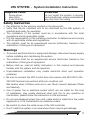
VAV SYSTEM - System Installation Instruction
Attention
Do not install the system in laundry
room or bathroom, where condensation
may drip from the ceiling.
Required tools
Screw driver.
1.
Hand Drill.
2.
6 mm Drill bit.
3.
Safety Instruction
Pay attention to the warning symbols in the document.
Verify that the Air condition unit to be controlled by the VAV system, is
installed and ready for operation.
The installation of the system must be in accordance with the local
regulations and all applicable codes.
It is the responsibility of the installing contractor to determine and comply
with all applicable codes and regulations.
The installer must be an experienced service technician, trained in the
installation of this type of equipment.
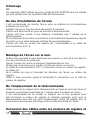
Warnings
To prevent electrical shock or equipment damage, disconnect power supply
before installing and maintaining the system.
The installer must be an experienced service technician trained in the
installation of this type of equipment.
Before start-up, read all safety instruction in this manual and become
familiar with the system and its operation.
Unprofessional installation may create electrical short and operation
problems.
Be sure to connect the VAC control box main power cord 230 VAC to the
230 VAC terminal connections at the air condition unit.
(Be careful when 3 Phase units are in use. Must connect between Phase
and Neutral).
Use of power line or electrical socket which are not made for this kind
of installation, may create electrical short and re. In any question or
clarication, please follow the instruction in this document.
Do not use damaged power line cord, cable which is made from few cable
segments or if it's connected to an extension cable.
Be careful to close the metal cover of the VAV controller.
Don't install the system in an area where there may be gas leakage.

4
All system elements are for use only inside the building.
If the power cable cord is damaged – replacement must be done by the
factory technician only.
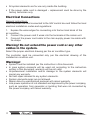
Electrical Connections
General instructions:
Use the power line cord connected to the VAV control box and follow the local
electrical installation codes and regulations:
Expose the wires edges for connecting into the terminal block of the
1.
air condition.
Connect the power cord 3 wires into the terminals at the indoor unit.
2.
Conjunct the power cord cable to the main supply power line cable with
3.
tie-wraps.
Warning! Do not extend the power cord or any other
cables in the system.
Select the proper electrical drawing per the air condition type.
The controller must be connected only per the electrical drawing of the
installed air condition unit.
Warnings!
System must be installed per the instruction in this document.
In case system elements will be used not according to the instruction
written in this document, warranty will be not valid.
Unprofessional installation and/or damage to the system elements will
cancel any warranty.
No eld repair allowed to any system elements.
System elements repair are not allowed.
Repair done by unauthorized personal will cancel warranty.
Line power operation of not standard and approved by the power company,
such as operation from generator or building that was not connected by
the power company will cancel warranty.

5
ENGLISH
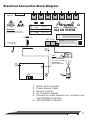
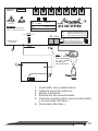
Electrical Connection Block Diagram.
3
4
2
NOTE:
CONNECT THE AIR-
COND. I/R RECEIVER
TO VAV SYSTEM
CONTROLLER
(NOT TO AIR-COND).
AC Line Power Input
230 VAC
ZONE - CONTROLLER
BYPASS
1 2 3 4
1 2
1 2
DIP #1,#2 - BYPASS PROFILE
DIP #3 - PARALLEL OPERATION ROOM #1+#2
FROM ONE IR RECEIVER AT ROOM #1.
DIP #4 - ROUND OR RECTANGULAR DAMPER.
WARNING:
Disconnect main power supply
before any system maintenance.
MEGA
TOOL
AIR
COND-
IR
RECEIVER
Danger
Electric shock
risc
Software Ver. C850-02-A11
C850-EU
POWER LINE INPUT
~230VAC/50HZ
1=ON
2=ON
>>>2X10”
1=OFF
2=ON
>>>2X8”
1=ON
2=OFF
>>>1X10”
1=OFF
2=OFF
>>>1X8”
For Damper
system only
[ 40 cm X 15 cm
And 50 cm X 15 cm]
[30 cm X 15 cm]
FUSE
0.3 Amps, 250 VAC
ROOM#1 ROOM#2 ROOM#3 ROOM#4 ROOM#5 ROOM#6
DLS VAV SYSTEM
Pay attention
The controller default is for Rectangular
dampers, for round damper need a special
set up, please refer to the installation manual.
1
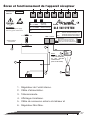
5
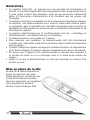
Indoor Unit Controller.
1.
Power Supply Cable.
2.
Remote control.
3.
Air Condition Display.
4.
Connection cable between Air condition and
5.
VAV SYSTEM Controller.
VAV SYSTEM Controller.
6.

6
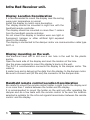
Infra Red Receiver unit.
Display Location Consideration
It is recommended to mount the display near the ceiling
were room temperature is normal.
Install the display to match room decoration.
The display should be mounted in sight line with the
handheld remote controller.
The display should be mounted no more then 7 meters
from the handheld remote controller.
Do not mount the display in location were sun light or
uorescent, halogen or other articial light exposed
direct to the display.
The display is connected to the damper motor via communication cable type
RJ11-4.
Display mounting on the wall.
Use electrical hand drill to drill one 6 mm hole in the wall for the plastic
anchor.
Open the back side of the display and mark the location of the hole.
Use the screw supplied to mount the display’s back on the wall.
The RJ11-4 communication connects the display to the damper motor. The
cable is
6 meter long and is delivering the data from the display to the damper motor.
Be sure to connect well (till the end) the connector at the damper side.
Handheld remote control Location Consideration
Be careful to mount the remote control holder in sight line to the display and
in no more then 7 meters between the holder and the display.
It is recommended to mount the holder on the wall only after operating the
damper and do a few tests with the remote control to be sure the location
selected is suitable for the infra red signals transmission between the remote
control and the display.

7
ENGLISH
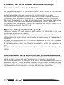
Cables Connection between damper motors and VAV
SYSTEM controller.
The damper motor connects direct to the controller with RJ45 type cable,
3 meters long.
Be careful to enter the plug into the socket at the motor side till the end, to
enable good electrical connection.
It is NOT allowed to extend this cable.
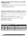
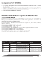
Damper Size definition and use of channels #1 and #2.
Near to channel #1 and #2 connectors, you will nd Dip Switches which allows
to select the size of the dampers and the number of dampers connected to
each channel.
Dip Sw. #1 selects the size of the damper 6”, 8” or 10”. (160mm, 200mm,
250mm)
Dip SW. #1 OFF = 6” or 8” Damper or 30 cm x 15 cm grill.
Dip SW. #1 ON = 10” Damper or 40 cm x 15 cm / 50cm X 15cm Grills.
Dip Sw. #2 denes if one or two dampers connected to the channel.
Dip SW. #2 OFF = One damper.
Dip SW. #2 ON = two dampers.
Dip SW. #2 ON not used with grills.
Channel #1 is factory set to damper size 10”.
Dip Sw. #1 Dip Sw. #2
Dampers Grills
ON ON 2 Dampers size 10" Not Applicble
OFF ON 2 Dampers size 8" Not Applicble
ON OFF One damper size 10"
One Grill 40
cm x
15
cm or
50
cm x
15
cm
OFF OFF One damper size 8" One Grill 30 cm x15 cm

8
1=ON
2=ON
>>>
2x10"
>>>
40/50x15 cm
1=OFF
2=ON
>>>
2x8"
>>>
30x15 cm
ON
ON
1 2
1 2
MOTORIZED
DAMPER 8”
IR RECEIVER
MOTORIZED
DAMPER 8”
MOTORIZED
DAMPER 10”
MOTORIZED
DAMPER 10”
IR TRANSMITER
SPLITER SPLITER
ROOM #1 ROOM #2
IR TRANSMITER
IR RECEIVER
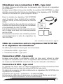
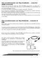
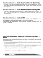
Cables Connection between air condition Displays
and VAV SYSTEM controller.
The Air condition is supplied with Infra red receiver display and Connection
cable 7 meters long.
This original cable is used to connect between the Air condition display and
the air condition controller.
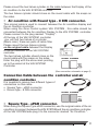
It is possible to receive two different types of connectors with the air condition
unit.
Square Type - ePAD connector.
Round type - 8 DIN connector.
Air condition with Square Type - ePAD connector•
Inside the VAV SYSTEM carton box you will nd additional cable 7 Meters
long, Use this cable between the VAV SYSTEM and the air condition display.
At the VAV SYSTEM , Plug it to the connector marked “ Display”
At the box of the VAV SYSTEM controller you will nd two halves of a cylinder.
(Black color) these are parts of cable lter.

9
ENGLISH
Please mount the two halves cylinder on the cable between the Display of the
air condition to the VAV SYSTEM controller.
The two halves cylinder should close on the round cable with the snaps on
the sides.
Air condition with Round type - 8 DIN connector.•
This original cable is used to connect between the Air condition display and
the air condition controller.
When using the Zone Control system VAV SYSTEM , this cable should be
connected between the Air condition Display to the VAV SYSTEM controller.
Please connect to the plug marked “Display”.
At the box of the VAV SYSTEM controller
you will nd two halves of a cylinder.
(Black color) these are parts of cable lter.
Please mount the two halves cylinder
on the original cable between the Display
of the air condition to the VAV SYSTEM
controller.
The two halves cylinder should close on the
round cable with the snaps on the sides.
Enter the plug with the arrow mark pointing
up to the socket at the VAV SYSTEM
Controller.
AIR COND. IR RECEIVER
MEGA
TOOL
(See connection schematic at page 5).
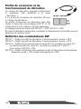
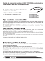
Connection Cable between the controller and air
condition controller.
It is possible to receive two different types of
connectors on this cable.
Square Type - ePAD connector.
Round type - 8 DIN connector.
AIR COND. IR RECEIVER
MEGA
TOOL
Square Type - ePAD connector.•
When using the Square Type ePAD connector, use the original cable of the air
condition to connect between the VAV SYSTEM and the air condition controller.
At the VAV SYSTEM side plug it to the connector marked “Air Condition “.

10
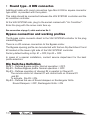
Round type - 8 DIN connector.•
Additional cable with round connectors type Mini 8 DIN or square connector
type ePAD is provided with the system.
This cable should be connected between the VAV SYSTEM controller and the
air condition controller.
At the VAV SYSTEM side, plug to the socket marked with “Air Condition”.
Enter the plug with the arrow mark face up.
See connection at page 5, cable market as No. 5
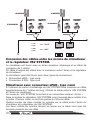
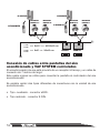
Bypass connection and working profiles
The Bypass motor connects direct to the VAV SYSTEM controller to the plug
marked Bypass.
There is no I/R receiver connection to the Bypass motor.
The Bypass opening prole can be selected with the two Dip Switches #1 and
#2 located at the lower right side of the VAV SYSTEM controller.
Factory default setting is Dip #1 = OFF, Dip #2 = OFF.
In cases of a special installation, contact service department for the best
prole selection.
Dip Switches Definition
Dip #1 – Denes Bypass prole. Normal operation = OFF.
Dip #2 - Denes Bypass prole. Normal operation = OFF.
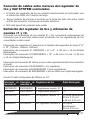
Dip #3 – Denes operation of channel #2 in parallel to Chanel #1.
The remote control of channel #1 will control both on Channel #1
and #2.
To activate, Dip #3 = ON.
Dip #4 – Denes the use of Round dampers or Rectangular Grills.
Round Dampers = OFF, Rectangular Grills = ON

11
ENGLISH
MOTORIZED
DAMPER 10”
MOTORIZED
DAMPER 10”
IR TRANSMITER
IR RECEIVER
Dip sw #3 - Parallel dampers/grilles
operation room. #1+#2
dip #4 - round or rectangular damper
ON
1 2
ON
1 2
1234
ON
ROOM #2ROOM #1
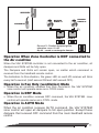
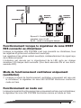
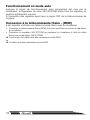
Operation When Zone Controller is NOT connected to
the Air condition
When the VAV SYSTEM controller is not connected to the air condition, all
dampers and Grills will be fully open.
The Dampers and Grills will remain open, no matter which command is
received from the handheld remote control.
The Indication to this situation, the green LED on each I/R receiver will blink
every half a second. (Half second ON and Half second OFF).
Operation in Fan Only (ventilation) Mode
When the air condition receives Fan Only command, the VAV SYSTEM
zone control will operate same as in COOL mode.
Operation in DRY Mode
When the air condition receives DRY command, the VAV SYSTEM zone
control will operate same as in COOL mode.
Operation in AUTO Mode
When the air condition receives AUTO command, the VAV SYSTEM
zone control will open all dampers to full open position. Except those
dampers that received OFF command from the room handheld remote
control.

12
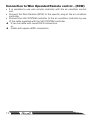
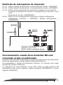
Connection to Wire Operated Remote control – (RCW)
It is possible to use wire remote controller with the air condition control
unit.
Connect the Wire Remote (RCW) to the specic plug at the air condition
controller.
Connect the VAV SYSTEM controller to the air condition controller by use
of the cable supplied with the VAV SYSTEM controller.
It can be cable with round DIN 8 connectors. Î
or
Cable with square ePAD connectors. Î

13
ENGLISH
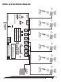
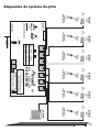
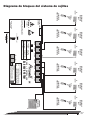
Grille system block diagram
ZONE - CONTROLLER
BYPASS
1 2 3 4
1 2
1 2
DIP #1,#2 - BYPASS PROFILE
DIP #3 - PARALLEL OPERATION ROOM #1+#2
FROM ONE IR RECEIVER AT ROOM #1.
DIP #4 - ROUND OR RECTANGULAR DAMPER.
WARNING:
Disconnect main power supply
before any system maintenance.
MEGA
TOOL
AIR
COND-
IR
RECEIVER
Danger
Electric shock
risc
Software Ver. C850-02-A11
C850-EU
POWER LINE INPUT
~230VAC/50HZ
1=ON
2=ON
>>>2X10”
1=OFF
2=ON
>>>2X8”
1=ON
2=OFF
>>>1X10”
1=OFF
2=OFF
>>>1X8”
For Damper
system only
[ 40 cm X 15 cm
And 50 cm X 15 cm]
[30 cm X 15 cm]
FUSE
0.3 Amps, 250 VAC
ROOM#1 ROOM#2 ROOM#3 ROOM#4 ROOM#5 ROOM#6
DLS VAV SYSTEM
Pay attention
The controller default is for Rectangular
dampers, for round damper need a special
set up, please refer to the installation manual.
AC Line Power Input
230 VAC
RECTANGULAR
MOTORIZED
GRILL
IR
receiver
HANDHELD IR
REMOTE CONTROL
RECTANGULAR
MOTORIZED
GRILL
IR
receiver
HANDHELD IR
REMOTE CONTROL
RECTANGULAR
MOTORIZED
GRILL
IR
receiver
HANDHELD IR
REMOTE CONTROL
RECTANGULAR
MOTORIZED
GRILL
IR
receiver
HANDHELD IR
REMOTE CONTROL
RECTANGULAR
MOTORIZED
GRILL
IR
receiver
HANDHELD IR
REMOTE CONTROL
RECTANGULAR
MOTORIZED
GRILL
IR
receiver
HANDHELD IR
REMOTE CONTROL
RECTANGULAR
MOTORIZED GRILL

14
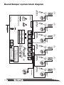
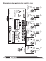
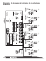
Round Damper system block diagram
ZONE - CONTROLLER
BYPASS
1 2 3 4
1 2
1 2
DIP #1,#2 - BYPASS PROFILE
DIP #3 - PARALLEL OPERATION ROOM #1+#2
FROM ONE IR RECEIVER AT ROOM #1.
DIP #4 - ROUND OR RECTANGULAR DAMPER.
WARNING:
Disconnect main power supply
before any system maintenance.
MEGA
TOOL
AIR
COND-
IR
RECEIVER
Danger
Electric shock
risc
Software Ver. C850-02-A11
C850-EU
POWER LINE INPUT
~230VAC/50HZ
1=ON
2=ON
>>>2X10”
1=OFF
2=ON
>>>2X8”
1=ON
2=OFF
>>>1X10”
1=OFF
2=OFF
>>>1X8”
For Damper
system only
[ 40 cm X 15 cm
And 50 cm X 15 cm]
[30 cm X 15 cm]
FUSE
0.3 Amps, 250 VAC
ROOM#1 ROOM#2 ROOM#3 ROOM#4 ROOM#5 ROOM#6
DLS VAV SYSTEM
Pay attention
The controller default is for Rectangular
dampers, for round damper need a special
set up, please refer to the installation manual.
AC Line Power Input
230 VAC
BYPASS DAMPER
MOTORIZED
DAMPER
IR
receiver
HANDHELD IR
REMOTE CONTROL
MOTORIZED
DAMPER
IR
receiver
HANDHELD IR
REMOTE CONTROL
MOTORIZED
DAMPER
IR
receiver
HANDHELD IR
REMOTE CONTROL
MOTORIZED
DAMPER
IR
receiver
HANDHELD IR
REMOTE CONTROL
MOTORIZED
DAMPER
IR
receiver
HANDHELD IR
REMOTE CONTROL
MOTORIZED
DAMPER
IR
receiver
HANDHELD IR
REMOTE CONTROL

15
ENGLISH
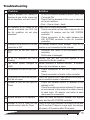
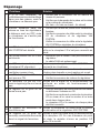
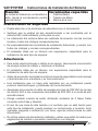
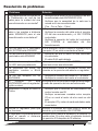
Troubleshooting
Problem Solution
1
There is demand for Cooling or
Heating at one of the rooms but
the air condition unit don't start?
At the Air condition operation panel Check that
it's turned ON.
Check that the demand at the room is same as
at the air condition.
(Cool – Cool or Heat – Heat)
2
No demand at all rooms or all
remote controllers are OFF but
the Air condition do not stop
operation?
Check that all rooms are closed.
Check connection of the cable between the Air
condition I/R receiver and the VAV SYSTEM
controller.
Check connection of the cable between the
VAV SYSTEM controller to the Air condition
controller.
3
Channel LED at the VAV SYSTEM
controller is OFF
It is normal situation when damper / Grill or I/R
receiver is not connected to the channel.
4
Motor LED at the Mini Max is
OFF
Indication that motor is not connected to the
controller.
RJ45 cable is damaged.
5
At All I/R receivers the LED's
blinking.
Indicate that the VAV SYSTEM system is not
connected to the Air condition.
6
Fan Motor speed changed to
LOW.
Normal operation in minimal demand , a situation
when only one damper is open.
7
I/R receiver LED do not turn ON. Check connection of the RJ11 cable to the
motor.
Check connection of motor to the controller.
8
I/R receiver is ON but the Damper/
Grill do not open.
Check the remote control has demand according to
the air condition mode of operation.
9
Damper or Grill do not Open or
Close
Check the Remote control ID address or set
address to 00.
Check for cross connection between I/R receiver
at one channel to the motor of an other channel
at each room. I/R receiver and motor of each
room must be connected.
10
Bypass damper to not operate. Check the cable connection between the Bypass
motor and the VAV SYSTEM controller.
11
Damper or Grill is Open but the
remote control calls for Close.
Check for eye sight between the remote control and
the I/R receiver. If there is no eye sight, the damper
will open to 2/3 position after 30 minutes.

16
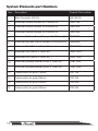
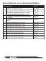
System Elements part Numbers
Item Description Product Part number
1 Main Controller VAV Kit 3PA139100
2
Motorized Round Damper (D=150mm) Kit CMR7150
3
Motorized Round Damper (D=200mm) Kit CMR7200
4
Motorized Round Damper (D=250mm) Kit CMR7250
5
Motorized ByPass Round Damper (D=200mm) Kit CMR8200
6
Motorized ByPass Round Damper (D=250mm) Kit CMR8250
7
Motorized Grill (30cm x 15cm) Kit CMG71530
8
Motorized Grill (40cm x 15cm) Kit CMG71540
9
Motorized Grill (50cm x 15cm) Kit CMG71550
10
Motorized Bypass damper (40cm x 15cm) Kit COB71540
11
Motorized Bypass damper (50cm x 15cm) Kit COB71550
12 Frame prole for grille 150mm CGF 150
13 Frame prole for grille 300mm CGF 300
14 Frame prole for grille 400mm CGF 400
15 Frame prole for grille 500mm CGF 500

17
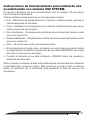
ENGLISH
Operation Instruction for Air condition unit with the
VAV SYSTEM system
The Air condition handheld remote control with the I/R receiver allows the
operation of the system.
The overall system can be operated in the following mode of operations:
Cool – Set the temperature set point at the Air Condition handheld remote
control to be same as the temperature required at the rooms.
Heat - Set the temperature set point at the Air Condition handheld remote
control to be same as the temperature required at the rooms.
Fan Only (Ventilation) – The Zone Control system will act same as at Cool
mode.
Dry - The Zone Control system will act same as at Cool mode.
A uto – Do not use this mode of operation.
In case Auto mode is selected, the zone control system will open all
dampers to full open position except the rooms which are OFF. The zone
control is not operated at the rooms.
When the system is not in use, turn OFF all handheld remote controls at
each room.
Note: When the system automatically changes the fan speed to Low speed, a
beep will be sound. This Beep sound is normal as the system gives indication
for reducing speed for balancing the air ow in the ducts.

18
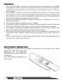
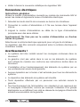
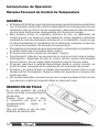
GENERAL
The VAV SYSTEM connects to mini-central air conditioners to facilitate
independent control over the temperature at each room for the occupants’
comfort and disconnection of air supply to unoccupied rooms in order so
save energy.
The system includes an electrically operated air damper, a remote control
and a sensor in every room. The damper controls the volume of conditioned
air entering the room, with the system setting the room’s temperature by
opening and closing the damper as required.
The air conditioning setting, cooling or heating, is determined by the air
conditioner itself.
The remote control’s range is up to 7 meters.
To transmit orders, the remote control must be aimed at the sensor. Take care
of aiming it directly at the sensor, with no object obtruding in between.
The sensor responds to signals transmitted from the remote control. The
sign of reception is the ickering of the sensor’s lights.
The sensor and the remote control must not be exposed to sunlight or to
uorescent light. Neither should they be exposed to any other source of
heat.
Care must be taken to avoid placing the remote control exposed to air ow
coming from the grid on the wall.
BATTERIES INSERTION
The Batteries compartment is located on the back of the remote control. Slide
down the cover and insert the
Batteries into the Batteries
compartment, according to the
illustration.
Two AAA alkaline Batteries are
to be used.

19
ENGLISH
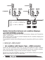
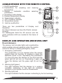
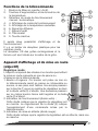
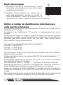
ACQUAINTANCE WITH THE REMOTE CONTROL
On/Off pushbutton
1.
Pushbuttons for elevating and lowering
2.
temperature
Manual / Automatic condition selecting
3.
pushbutton
Operating mode display
4.
Desired temperature display
5.
Transmission indicator
6.
“Off” condition indicator
7.
Temperature sensor
8.
Inactive pushbutton
9.
There are two posiabilities of Display and
Operation.
For Round dampers we have the Plastic receiver
housing.
For Rectangular Grills the I/R receiver and the
green indication LED are located at the frame of
the grill
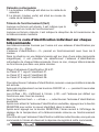
DISPLAY AND OPERATION (RECEIVER) UNIT
Round dampers:
The receiver unit includes lights and a pushbutton,
which enables manual operation when the remote
control is failing or missing (emergency case).
Emergency pushbutton
1.
This pushbutton is to be applied when the remote
control does not function, is missing or when the
Batteries power is low. Depressing the pushbutton
(1) once will open the damper to one third and the
green light (2) will turn on. Depressing it again will
close the damper and the green light (2) will turn
off.
Working light (green)
2.
This light indicates that the damper is in working
condition. Flickering of the light (2) indicates
reception of the remote control’s transmission.
Standby light (red)
3.
This light indicates that the damper is standing by but not working.
3
1
2

20
1
2
Rectangular Grill
The Infra Red receiver is located at the frame of
1.
the grill.
The Indication light (Green Color) is located at the
2.
frame of the grill.
Working Light (Green)
When this light is ON, it’s indicating that the grill is in working mode.
When this light Blinking, it indicates transmission reception from the
handheld remote control.
Define individual ID code to each Remote control
The remote controllers supplied from the factory with default ID address of
“0”. (Zero)
ID address of “0” allows operation with all 6 channels.
In situation where one remote control effects more then one room (cross
talk), it is possible to select individual ID address to each remote control.
In this case every remote will operate only to that specic room.
ID Address range from 00 to 07.
Channel No. 1 receives ID 01.
Channel No. 2 receives ID 02.
Channel No. 6 receives ID 06.
To select ID address, be sure that the remote control is ON.
Press at same time both on the ON/OFF and “+” buttons for continues
6 seconds.
On the display will appear the numbers “00”. (“00” is the default address
operates all channels).
With the Up “+” and Down “-” buttons select the required ID address.
After reaching to the required ID address, press the DAMPER button to
enter the new ID into the memory.
After pressing the DAMPER button, the display will return to display the
temperature set point and the remote will return to normal operation.
To be sure that the new ID address was selected well, send a command
to the display and watch that the damper response to that command.
La page est en cours de chargement...
La page est en cours de chargement...
La page est en cours de chargement...
La page est en cours de chargement...
La page est en cours de chargement...
La page est en cours de chargement...
La page est en cours de chargement...
La page est en cours de chargement...
La page est en cours de chargement...
La page est en cours de chargement...
La page est en cours de chargement...
La page est en cours de chargement...
La page est en cours de chargement...
La page est en cours de chargement...
La page est en cours de chargement...
La page est en cours de chargement...
La page est en cours de chargement...
La page est en cours de chargement...
La page est en cours de chargement...
La page est en cours de chargement...
La page est en cours de chargement...
La page est en cours de chargement...
La page est en cours de chargement...
La page est en cours de chargement...
La page est en cours de chargement...
La page est en cours de chargement...
La page est en cours de chargement...
La page est en cours de chargement...
La page est en cours de chargement...
La page est en cours de chargement...
La page est en cours de chargement...
La page est en cours de chargement...
La page est en cours de chargement...
La page est en cours de chargement...
La page est en cours de chargement...
La page est en cours de chargement...
La page est en cours de chargement...
La page est en cours de chargement...
La page est en cours de chargement...
La page est en cours de chargement...
La page est en cours de chargement...
La page est en cours de chargement...
La page est en cours de chargement...
La page est en cours de chargement...
La page est en cours de chargement...
La page est en cours de chargement...
La page est en cours de chargement...
La page est en cours de chargement...
-
 1
1
-
 2
2
-
 3
3
-
 4
4
-
 5
5
-
 6
6
-
 7
7
-
 8
8
-
 9
9
-
 10
10
-
 11
11
-
 12
12
-
 13
13
-
 14
14
-
 15
15
-
 16
16
-
 17
17
-
 18
18
-
 19
19
-
 20
20
-
 21
21
-
 22
22
-
 23
23
-
 24
24
-
 25
25
-
 26
26
-
 27
27
-
 28
28
-
 29
29
-
 30
30
-
 31
31
-
 32
32
-
 33
33
-
 34
34
-
 35
35
-
 36
36
-
 37
37
-
 38
38
-
 39
39
-
 40
40
-
 41
41
-
 42
42
-
 43
43
-
 44
44
-
 45
45
-
 46
46
-
 47
47
-
 48
48
-
 49
49
-
 50
50
-
 51
51
-
 52
52
-
 53
53
-
 54
54
-
 55
55
-
 56
56
-
 57
57
-
 58
58
-
 59
59
-
 60
60
-
 61
61
-
 62
62
-
 63
63
-
 64
64
-
 65
65
-
 66
66
-
 67
67
-
 68
68


Airwell DLS VAV SYSTEM Installation And Operation Instructions Manual
- Taper
- Installation And Operation Instructions Manual
dans d''autres langues
- English: Airwell DLS VAV SYSTEM
- español: Airwell DLS VAV SYSTEM
Autres documents
-
Haverland EMISORES RCW Le manuel du propriétaire
-
Trane Horizon OAGD180 Series Installation, Operation and Maintenance Manual
-
-
Johnson Controls NS Series Installation Instructions Manual
-
Honeywell MN6105VAV Installation Instructions Manual
-
ClimateMaster Dedicated Outside Air Systems Le manuel du propriétaire
-
OJ Electronics OJ-Zone-Module-MP Mode d'emploi
-
-
-