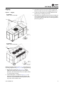
Trane Horizon OAGD180 Series Installation, Operation and Maintenance Manual
- Catégorie
- Pompes à chaleur
- Taper
- Installation, Operation and Maintenance Manual

SAFETY WARNING
Only qualified personnel should install and service the equipment. The installation, starting up, and servicing
of heating, ventilating, and air-conditioning equipment can be hazardous and requires specific knowledge and
training. Improperly installed, adjusted or altered equipment by an unqualified person could result in death or
serious injury. When working on the equipment, observe all precautions in the literature and on the tags,
stickers, and labels that are attached to the equipment.
AVERTISSEMENT DE SÉCURITÉ
L’installation et l’entretien de cet équipement doivent être assurés exclusivement par du personnel qualifié.
L’installation, la mise en service et l’entretien d’équipements de chauffage, de ventilation et de climatisation
(CVC) présentent un danger et requièrent des connaissances et une formation spécifiques. Une installation,
un réglage ou une modification inappropriés d’un équipement par une personne non qualifiée peut provoquer
des blessures graves, voire la mort. Lors de toute intervention sur l’équipement, respectez les consignes de
sécurité figurant dans la documentation, ainsi que sur les pictogrammes, autocollants et étiquettes apposés
sur l’équipement.
Installation, Operation,
and Maintenance
Important: Proper execution of the tasks outlined in this Installation, Operation, and Maintenance manual
require and assume the technician has been certified as a start up technician for the Horizon Outdoor
Air unit. This includes working knowledge of the Tracer TU program.
Horizon™ Outdoor Air Unit
Direct Gas-Fired
Model: OAB, OAG
International Inc.
KCC
OAU-SVX005C-EN
November 2019

© 2019 Ingersoll Rand OAU-SVX005C-EN
Introduction
Read this manual thoroughly before operating or servicing
this unit.
Warnings, Cautions, and Notices
Safety advisories appear throughout this manual as
required. Your personal safety and the proper operation of
this machine depend upon the strict observance of these
precautions.
Important Environmental Concerns
Scientific research has shown that certain man-made
chemicals can affect the earth’s naturally occurring
stratospheric ozone layer when released to the
atmosphere. In particular, several of the identified
chemicals that may affect the ozone layer are refrigerants
that contain Chlorine, Fluorine and Carbon (CFCs) and
those containing Hydrogen, Chlorine, Fluorine and
Carbon (HCFCs). Not all refrigerants containing these
compounds have the same potential impact to the
environment. Trane advocates the responsible handling of
all refrigerants-including industry replacements for CFCs
and HCFCs such as saturated or unsaturated HFCs and
HCFCs.
Important Responsible Refrigerant
Practices
Trane believes that responsible refrigerant practices are
important to the environment, our customers, and the air
conditioning industry. All technicians who handle
refrigerants must be certified according to local rules. For
the USA, the Federal Clean Air Act (Section 608) sets forth
the requirements for handling, reclaiming, recovering and
recycling of certain refrigerants and the equipment that is
used in these service procedures. In addition, some states
or municipalities may have additional requirements that
must also be adhered to for responsible management of
refrigerants. Know the applicable laws and follow them.
The three types of advisories are defined as follows:
WARNING
Indicates a potentially hazardous
situation which, if not avoided, could
result in death or serious injury.
CAUTIONs
Indicates a potentially hazardous
situation which, if not avoided, could
result in minor or moderate injury. It
could also be used to alert against
unsafe practices.
NOTICE:
Indicates a situation that could result in
equipment or property-damage only
accidents.
WARNING
Proper Field Wiring and Grounding
Required!
Failure to follow code could result in death or serious
injury. All field wiring MUST be performed by qualified
personnel. Improperly installed and grounded field
wiring poses FIRE and ELECTROCUTION hazards. To
avoid these hazards, you MUST follow requirements for
field wiring installation and grounding as described in
NEC and your local/state electrical codes.
AVERTISSEMENT
Câblage sur site et mise à la terre corrects
nécessaires!
Le non-respect de la réglementation peut entraîner des
blessures graves, voire mortelles. Il est IMPÉRATIF de
confier l’ensemble du câblage sur site à un électricien
qualifié. Un câblage sur site mal installé ou mal mis à la
terre constitue des risques D’INCENDIE et
D’ÉLECTROCUTION. Pour éviter ces risques, il est
IMPÉRATIF de respecter les obligations en matière de
pose de câblage sur site et de mise à la terre tel que
stipulé dans les règles du NEC et dans les
réglementations électriques locales/nationales.

Introduction
OAU-SVX005C-EN 3
WARNING
Personal Protective Equipment (PPE)
Required!
Failure to wear proper PPE for the job being undertaken
could result in death or serious injury. Technicians, in
order to protect themselves from potential electrical,
mechanical, and chemical hazards, MUST follow
precautions in this manual and on the tags, stickers,
and labels, as well as the instructions below:
• Before installing/servicing this unit, technicians
MUST put on all PPE required for the work being
undertaken (Examples; cut resistant gloves/sleeves,
butyl gloves, safety glasses, hard hat/bump cap, fall
protection, electrical PPE and arc flash clothing).
ALWAYS refer to appropriate Material Safety Data
Sheets (MSDS)/Safety Data Sheets (SDS) and OSHA
guidelines for proper PPE.
• When working with or around hazardous chemicals,
ALWAYS refer to the appropriate MSDS/SDS and
OSHA/GHS (Global Harmonized System of
Classification and Labelling of Chemicals) guidelines
for information on allowable personal exposure
levels, proper respiratory protection and handling
instructions.
• If there is a risk of energized electrical contact, arc, or
flash, technicians MUST put on all PPE in accordance
with OSHA, NFPA 70E, or other country-specific
requirements for arc flash protection, PRIOR to
servicing the unit. NEVER PERFORM ANY
SWITCHING, DISCONNECTING, OR VOLTAGE
TESTING WITHOUT PROPER ELECTRICAL PPE AND
ARC FLASH CLOTHING. ENSURE ELECTRICAL
METERS AND EQUIPMENT ARE PROPERLY RATED
FOR INTENDED VOLTAGE.
AVERTISSEMENT
Équipements de protection individuelle
(EPI) obligatoires!
En cas d’équipement de protection individuelle
inadapté au travail entrepris, les techniciens s’exposent
à des risques de blessures graves voire mortelles. Afin
de se prémunir d’éventuels risques électriques,
mécaniques et chimiques, les techniciens DOIVENT
respecter les consignes préconisées dans le présent
manuel, sur les étiquettes et les autocollants, ainsi que
les instructions suivantes :
• Avant d’installer/réparer cette unité, les techniciens
doivent IMPÉRATIVEMENT porter tout l’équipement
de protection individuelle (EPI) recommandé pour le
travail entrepris (exemples: gants/manchons
résistants aux coupures, gants en caoutchouc butyl,
lunettes de protection, casque de chantier/antichoc,
protection contre les chutes, EPI pour travaux
électriques et vêtements de protection contre les arcs
électriques). Consulter SYSTÉMATIQUEMENT les
fiches de données de sécurité et les directives de
l’OSHA pour connaître la liste des EPI adaptés.
• Lors d’une intervention avec ou à proximité de
produits chimiques dangereux, consulter
SYSTÉMATIQUEMENT les fiches de données de
sécurité appropriées et les directives de l’OSHA/du
SGH (système général harmonisé de classification et
d’étiquetage des produits chimiques) afin d’obtenir
des renseignements sur les niveaux admissibles
d’exposition personnelle, la protection respiratoire
adaptée et les recommandations de manipulation.
• En cas de risque d’éclair, d’arc électrique ou de
contact électrique avec un équipement électrique
sous tension, et AVANT de réparer l’unité, les
techniciens doivent IMPÉRATIVEMENT porter tout
l’équipement de protection individuelle (EPI)
conformément à l’OSHA, à la norme NFPA 70E ou à
toute autre exigence propre au pays pour la
protection contre les arcs électriques. NE JAMAIS
COMMUTER, DÉBRANCHER ou EFFECTUER DE TEST
DE TENSION SANS PORTER UN EPI POUR TRAVAUX
ÉLECTRIQUES OU UN VÊTEMENT DE PROTECTION
APPROPRIÉ CONTRE LES ARCS ÉLECTRIQUES. IL
CONVIENT DE S’ASSURER QUE LES COMPTEURS ET
ÉQUIPEMENTS ÉLECTRIQUES CORRESPONDENT À
LA TENSION NOMINALE PRÉVUE.

Introduction
4 OAU-SVX005C-EN
WARNING
Follow EHS Policies!
Failure to follow instructions below could result in
death or serious injury.
• All Ingersoll Rand personnel must follow Ingersoll
Rand Environmental, Health and Safety (EHS)
policies when performing work such as hot work,
electrical, fall protection, lockout/tagout, refrigerant
handling, etc. All policies can be found on the BOS
site. Where local regulations are more stringent than
these policies, those regulations supersede these
policies.
• Non-Ingersoll Rand personnel should always follow
local regulations.
AVERTISSEMENT
Respecter les politiques EHS!
Le non-respect des consignes suivantes peut être à
l’origine de blessures graves, voire mortelles.
• Tous les membres du personnel du groupe Ingersoll
Rand sont tenus de respecter les règles établies par
Ingersoll Rand en matière d’environnement,
d’hygiène et de sécurité (EHS) lors d’une
intervention, notamment en cas de travaux à chaud,
de risque d’électrocution et de chute, de procédures
de verrouillage/mise hors service, de manipulation
de fluide frigorigène, etc. Toutes les politiques sont
disponibles sur le site BOS. Si les réglementations
locales sont plus strictes que les règles imposées par
le groupe, elles deviennent prioritaires.
• Le personnel extérieur au groupe Ingersoll Rand est,
quant à lui, systématiquement tenu d’observer les
réglementations en vigueur à l’échelle locale.
WARNING
Refrigerant under High Pressure!
Failure to follow instructions below could result in an
explosion which could result in death or serious injury
or equipment damage. System contains oil and
refrigerant under high pressure. Recover refrigerant to
relieve pressure before opening the system. See unit
nameplate for refrigerant type. Do not use non-
approved refrigerants, refrigerant substitutes, or
refrigerant additives.
AVERTISSEMENT
Fluide frigorigène sous haute pression!
Tout manquement aux instructions indiquées ci-
dessous peut provoquer une explosion pouvant causer
des blessures graves voire mortelles ou des dommages
matériels. Le système contient de l’huile et du fluide
frigorigène sous haute pression. Avant d’ouvrir le
circuit, récupérez le fluide frigorigène pour éliminer
toute pression dans le circuit. Consultez la plaque
constructeur de l’unité pour connaître le type de fluide
frigorigène employé. Utilisez uniquement des fluides
frigorigènes, substituts et additifs agréés.
WARNING
Hazard of Explosion and Deadly Gases!
Failure to follow all proper safe refrigerant handling
practices could result in death or serious injury.
Never solder, braze or weld on refrigerant lines or any
unit components that are above atmospheric pressure
or where refrigerant may be present. Always remove
refrigerant by following the guidelines established by
the EPA Federal Clean Air Act or other state or local
codes as appropriate. After refrigerant removal, use dry
nitrogen to bring system back to atmospheric pressure
before opening system for repairs. Mixtures of
refrigerants and air under pressure may become
combustible in the presence of an ignition source
leading to an explosion. Excessive heat from soldering,
brazing or welding with refrigerant vapors present can
form highly toxic gases and extremely corrosive acids.
AVERTISSEMENT
Risque d’explosion et gaz mortels!
Le non-respect de toutes les consignes de manipulation
des fluides frigorigènes peut entraîner la mort ou des
blessures graves.
N’effectuez en aucune circonstance des opérations de
brasage ou de soudage sur des conduites de fluide
frigorigène ou des composants de l’unité sous pression
ou pouvant contenir du fluide frigorigène. Récupérez
systématiquement le fluide frigorigène en respectant
les directives de la loi américaine sur la propreté de l’air
(Agence fédérale pour l’environnement) ou toute autre
réglementation nationale ou locale en vigueur. Après la
récupération du fluide frigorigène, utilisez de l’azote
déshydraté pour ramener le système à la pression
atmosphérique avant de l’ouvrir pour procéder aux
réparations. Les mélanges de fluide frigorigène et d’air
sous pression peuvent devenir combustibles en
présence d’une source d’inflammation et provoquer
une explosion. La chaleur excessive découlant de
travaux de soudage ou de brasage associée à la
présence de vapeurs de fluide frigorigène peut entraîner
la formation de gaz hautement toxiques et d’acides
extrêmement corrosifs.

Introduction
OAU-SVX005C-EN 5
Copyright
This document and the information in it are the property of
Trane, and may not be used or reproduced in whole or in
part without written permission. Trane reserves the right
to revise this publication at any time, and to make changes
to its content without obligation to notify any person of
such revision or change.
Trademarks
All trademarks referenced in this document are the
trademarks of their respective owners.
Revision History
Added French language translations of warnings.
WARNING
Hazard of Explosion and Deadly Gases!
Failure to follow instructions could result in death or
serious injury.
If you smell gas:
1. Open windows.
2. Don’t touch electrical switches.
3. Extinguish any open flame.
4. Immediately call your gas supplier.
AVERTISSEMENT
Risque d’explosion et gaz mortels!
Le non-respect de toutes les consignes de sécurité ci-
dessous peut entraîner la mort ou des blessures graves.
Si vous sentez une odeur de gaz:
1. Ouvrez les fenêtres.
2. Ne touches à aucun interrupteur.
3. Éteignez toute flamme nue.
4. Avertissez immédiatement votre fournisseur de gaz.
WARNING
Hazardous Service Procedures!
Improper installation, adjustment, alteration, service or
maintenance can cause property damage, injury or
death. Read the installation, operating and
maintenance instructions thoroughly before installing
or servicing this equipment.
AVERTISSEMENT
Procédures d’entretien dangereuses!
Une installation, un réglage, une modification, une
réparation ou un entretien incorrect peut entraîner des
dommages matériels, des blessures ou la mort. Lisez
attentivement les instructions d’installation, de
fonctionnement et d’entretien avant de procéder à
l’installation ou à l’entretien de cet équipement.
WARNING
Hazard of Explosion and Deadly Gases!
Failure to follow instructions could result in death or
serious injury.
The use and storage of gasoline or other flammable
vapors and liquids in open containers in the vicinity of
this appliance is hazardous.
AVERTISSEMENT
Risque d’explosion et gaz mortels!
Le non-respect de toutes les consignes de sécurité ci-
dessous peut entraîner la mort ou des blessures graves.
Il est dangereux d’utiliser ou d’entreposer de l’essence
ou autres liquides ou vapeurs inflammables dans des
récipients ouverts à proximité de cet appareil.

6 OAU-SVX005C-EN
Table of Contents
Model Number Descriptions . . . . . . . . . . . . . . 8
Horizon Outdoor Air Unit . . . . . . . . . . . . . . . 8
General Information . . . . . . . . . . . . . . . . . . . . 11
Overview of Manual . . . . . . . . . . . . . . . . . 11
Model Number Description . . . . . . . . . . . 11
Unit Nameplate . . . . . . . . . . . . . . . . . . . . 11
Compressor Nameplate . . . . . . . . . . . . . . 11
Unit Description . . . . . . . . . . . . . . . . . . . . 11
Indoor Fan Failure Input . . . . . . . . . . . . . 11
Low Pressure Control ReliaTel Control . 11
Refrigerant Circuits . . . . . . . . . . . . . . . . . 11
High Pressure Control ReliaTel Control . 11
Space Temperature / RH Sensor (Optional)
12
High Temperature Sensor . . . . . . . . . . . . 12
Outdoor Air Temperature and Relative Hu-
midity Sensor . . . . . . . . . . . . . . . . . . . . . . 12
Control Input (Occupied / Unoccupied) . 12
Hot Gas Reheat . . . . . . . . . . . . . . . . . . . . . 12
100 Percent Outdoor Air Hood with Damper
and Filters . . . . . . . . . . . . . . . . . . . . . . . . . 12
Through the Base Electrical with Disconnect
Switch . . . . . . . . . . . . . . . . . . . . . . . . . . . . 12
Hinged Access Doors . . . . . . . . . . . . . . . . 12
Unit Inspection . . . . . . . . . . . . . . . . . . . . . . . 12
First Aid Measures . . . . . . . . . . . . . . . . . . 13
Storage . . . . . . . . . . . . . . . . . . . . . . . . . . . 13
Unit Clearances . . . . . . . . . . . . . . . . . . . . 13
Unit Clearances, Curb Dimensions, and Dimen-
sional Data
. . . . . . . . . . . . . . . . . . . . . . . . . . . . . 14
Direct-Fired OAB Units . . . . . . . . . . . . . . . 14
Direct-Fired OAG Units . . . . . . . . . . . . . . 15
Unit Weight and Rigging . . . . . . . . . . . . . . . . 16
Unit Weight . . . . . . . . . . . . . . . . . . . . . . . . 16
Rigging . . . . . . . . . . . . . . . . . . . . . . . . . . . 17
Installation . . . . . . . . . . . . . . . . . . . . . . . . . . . . . 18
Ductwork . . . . . . . . . . . . . . . . . . . . . . . . . . 18
General Unit Requirements . . . . . . . . . . . 18
Main Electrical Power Requirements . . . 19
Condensate Drain Configuration . . . . . . 19
Filter Installation . . . . . . . . . . . . . . . . . . . . .19
Field Installed Power Wiring . . . . . . . . . . .20
Main Unit Power . . . . . . . . . . . . . . . . . . . . . .21
Standard Wiring . . . . . . . . . . . . . . . . . . . . .21
Voltage Imbalance . . . . . . . . . . . . . . . . . . .21
Electrical Phasing (Three-Phase Motors) .22
Compressor Crankcase Heaters . . . . . . . .23
Main Unit Display and ReliaTel Controls .23
Field-Installed Control Wiring . . . . . . . . . .23
Control Power Transformer . . . . . . . . . . .23
Controls Using 24 Vac . . . . . . . . . . . . . . . .24
Controls Using DC Analog Input/Output
(Standard Low Voltage Multiconductor Wire)
24
DC Conductors . . . . . . . . . . . . . . . . . . . . . . . .25
System Configuration and Pre-Start . . . . . . .26
Startup . . . . . . . . . . . . . . . . . . . . . . . . . . . . . . . . .29
Direct Heating Startup . . . . . . . . . . . . . . . . .29
Direct Gas-Fired Heating Start-Up Procedure
30
Initiate . . . . . . . . . . . . . . . . . . . . . . . . . . . . .32
Standby . . . . . . . . . . . . . . . . . . . . . . . . . . . .33
Normal Start-up Pre-purge . . . . . . . . . . . .33
Ignition Trials . . . . . . . . . . . . . . . . . . . . . . .33
Run . . . . . . . . . . . . . . . . . . . . . . . . . . . . . . .33
Settings and Adjustments . . . . . . . . . . . . .34
Operation of the Direct Spark Ignition Control
Gas Valve . . . . . . . . . . . . . . . . . . . . . . . . . .34
Maintenance . . . . . . . . . . . . . . . . . . . . . . . . . . . .36
Monthly Maintenance . . . . . . . . . . . . . . . . . .36
Filters . . . . . . . . . . . . . . . . . . . . . . . . . . . . . .36
Supply/Return Air Smoke Detector Mainte-
nance . . . . . . . . . . . . . . . . . . . . . . . . . . . . . .36
Cooling Season . . . . . . . . . . . . . . . . . . . . .36
Heating Season . . . . . . . . . . . . . . . . . . . . .36
Condenser Coil Cleaning . . . . . . . . . . . . . .36
Direct-Fired Unit Maintenance Schedule . .38
Lubrication Requirements . . . . . . . . . . . . .39
Pillow Block Bearings . . . . . . . . . . . . . . . .40
Frequency of Lubrication . . . . . . . . . . . . . .40

Table of Contents
OAU-SVX005C-EN 7
Dampers . . . . . . . . . . . . . . . . . . . . . . . . . . 40
Air Filters . . . . . . . . . . . . . . . . . . . . . . . . . . 40
Belt Tensions and Adjustments . . . . . . . 41
Suggested Belt Tension Method . . . . . . . 41
Gaskets . . . . . . . . . . . . . . . . . . . . . . . . . . . 41
Annual Maintenance . . . . . . . . . . . . . . . . 41
Heater Maintenance . . . . . . . . . . . . . . . . . 41
Inspection and Maintenance of Gas Ports 43
Final Process . . . . . . . . . . . . . . . . . . . . . . . . . 43
Performance Data . . . . . . . . . . . . . . . . . . . . . . 45
Superheat and Refrigeration Circuit Data 49
Alarms and Troubleshooting . . . . . . . . . . . . 51
Microprocessor Control . . . . . . . . . . . . . . 51
System Alarms . . . . . . . . . . . . . . . . . . . . . 51
Sensor Failure Alarm Display . . . . . . . . . 51
RTRM Failure Modes . . . . . . . . . . . . . . . . 53
Airflow Troubleshooting . . . . . . . . . . . . . 53
Direct-Fired OAB and OAG Unit Flame Relays
£ 400 MBh . . . . . . . . . . . . . . . . . . . . . . . . . 54
Direct-Fired OAG Unit Flame Relays >
400 MBh . . . . . . . . . . . . . . . . . . . . . . . . . . 55
Appendix . . . . . . . . . . . . . . . . . . . . . . . . . . . . . . 59
OAU Filter Guide . . . . . . . . . . . . . . . . . . . . . 59

8 OAU-SVX005C-EN
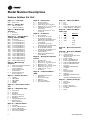
Model Number Descriptions
Horizon Outdoor Air Unit
Digit 1, 2 — Unit Type
OA = Outdoor Air
Digit 3 — Cabinet Size
B = 500 cfm–3,000 cfm
G = 1,250 cfm–7,500 cfm
Digit 4 — Major Design
Sequence
D = Revision 1
E = Heat Pump
Digit 5, 6, 7 — Normal Gross
Cooling Capacity (MBh)
000 = No Cooling
036 = 3 Tons High Efficiency
048 = 4 Tons High Efficiency
060 = 5 Tons High Efficiency
072 = 6 Tons High Efficiency
084 = 7 Tons High Efficiency
096 = 8 Tons High Efficiency
108 = 9 Tons High Efficiency
120 = 10 Tons High Efficiency
144 = 12 Tons High Efficiency
180 = 15 Tons High Efficiency
210 = 17 Tons High Efficiency
240 = 20 Tons High Efficiency
264 = 22 Tons High Efficiency
300 = 25 Tons High Efficiency
360 = 30 Tons High Efficiency
Digit 8 — Minor Design
Sequence
A = Vertical Discharge/Vertical Return
B = Vertical Discharge/
Horizontal Return
C = Horizontal Discharge/
Vertical Return
D = Horizontal Discharge/
Horizontal Return
Digit 9 — Voltage Selection
1 = 115/60/1
2 = 208-230/60/1
3 = 208-230/60/3
4 = 460/60/3
5 = 575/60/3
Digit 10 — Reserved for Future
Use
Digit 11 — Evaporator Type
0 = No Cooling
A = DX 3-Row
B = DX 4-Row
C = DX 4-Row Interlaced
D = DX 6-Row Interlaced
E = DX 8-Row
F = Glycol/Chilled Water Coil
G = DX 4-Row with
MSP
®
Technology
Digit 12 — Hot Gas Reheat
0= No HGRH
1 = Fin and Tube Modulating
2 = Fin and Tube On/Off
3 = Microchannel Modulating
4 = Microchannel On/Off
Digit 13 — Compressor
0= No Compressors
A = Scroll Compressors
B = Digital Scroll (1
st
Circuit Only)
C = Digital Scroll (1
st
and 2
nd
Circuit)
D = Variable Speed Scroll (1
st
Circuit Only)
E = Variable Speed Scroll (1
st
and
2
nd
Circuit)
Digit 14 — Condenser
0 = No Condenser
1 = Air-Cooled Fin and Tube
2 = Air-Cooled Fin and Tube
w/Head Pressure On/Off Control
3 = Water-Cooled DX Condenser
Copper/Steel
4 = Air-Cooled Fin and Tube
w/Head Pressure Variable Speed
5 = Air-Cooled Microchannel
6 = Air-Cooled Microchannel
w/Head Pressure On/Off Control
7 = Air-Cooled Microchannel
Variable Speed
8 = Water-Cooled DX Condenser
Copper/Nickel
Digit 15 — Refrigerant Capacity
Control
0 = No RCC Valve
A = RCC Valve on 1
st
Circuit
B = RCC Valve on 1
st
and 2
nd
Circuit
C = ERCC Valve on 1
st
Circuit
D = ERCC Valve on 1
st
and 2
nd
Circuit
E = HGBP Valve on 1
st
Circuit
F = HGBP Valve on 1
st
and
2
nd
Circuit
Digit 16 — Indoor Fan Motor
(IFM)
0 = ECM w/Backward Curved
Plenum Fan
1 = Direct Drive w/ VFD
2 = Belt Drive
3 = Belt Drive w/VFD
4 = Special Motor Option
Digit 17 — Indoor Fan Wheel
A = 355
B = 450
C = 450 X 2
D = 12/9 T2 (Single Fan—Belt Drive)
E = 12/9 BT (Dual Fan—Belt Drive)
Digit 18 — Indoor Fan Motor
Power (hp)
Digit 19 — Reserved for Future
Use
Digit 20 — Heat Type (PRI/SEC)
0 = No Heat
A = Indirect-Fired (IF)
B = No Primary Heat, Direct-Fired
(DF) Secondary
C = Electric—Stage
D = Electric—SCR Modulating
E = Dual Fuel (PRI-IF/SEC-DF)
F = Dual Fuel (PRI-ELEC/SEC-DF)
G = Dual Fuel (PRI-IF/SEC-ELEC)
H = Dual Fuel
(PRI-ELEC-SCR/SEC-ELEC)
J = Hot Water
K = Steam
L = No Primary Heat,
Secondary ELEC
M = Dual Fuel
(PRI-ELEC-STAGED/SEC-DF)
N = Dual Fuel
(PRI-ELEC-STAGED/SEC-ELEC)
Digit 21 — Primary Fuel Type
0 = No Heat
1= Natural Gas
2 = Propane
3 = Electric—Open Coil
4 = Electric—Sheathed Coil
5 = Hot Water
6 = Steam
ECM Belt Drive
A = 1 kW 2 hp
B = 2 kW 3 hp
C = 3 kW 5 hp
D = 4 kW 7.5 hp
E = 10 hp
F = 15 hp

Model Number Descriptions
OAU-SVX005C-EN 9
Digit 22 — Heat Capacity
(Primary Heat Source)
Digit 23 — Heat Capacity
(Secondary Heat Source)
Digit 24 — Corrosive
Environment Package
0 = No Corrosive Package
1 = S/S Interior, S/S Evap Coil Casing
2 = S/S Interior, Eco Coated Coils
3 = S/S Interior,
Copper/Copper Evap Coil
4 = S/S Coil Casing
5 = S/S Interior
6 = Eco-Coated Coils
7 = S/S Coil Casing with
Eco-Coated Coils
8 = Copper/Copper Evap,
HGRH Coils
Digit 25, 26 — Unit Controls
00 = Non-DDC—Electromechanical
AA = Trane—Discharge Air Control
w/LON Read-Write w/Display
AB = Trane—Space Control w/LON
Read-Write w/Display
AC = Trane—Discharge Air Control
w/BACnet
®
(No Display)
AD = Trane—Space Control
w/BACnet (No Display)
AF = Trane—Discharge Air Control
w/BACnet w/Display
AG = Trane—Space Control
w/BACnet w/Display
AI = Trane—Discharge Air Control
w/LON Read-Write (No Display)
AJ = Trane—Space Control
w/LON Read-Write (No Display)
AK = Trane—Multi-Zone VAV Control
w/LON Read-Write w/Display
AL = Trane—Multi-Zone VAV Control
w/BACnet w/Display
AM = Trane—Multi-Zone VAV Control
w/LON Read-Write (No Display)
AN = Trane—Multi-Zone VAV Control
w/BACnet (No Display)
AO = Trane—Single-Zone VAV Control
w/LON Read-Write w/Display
AP = Trane—Single-Zone VAV Control
w/BACnet w/Display
AQ = Trane—Single-Zone VAV Control
w/LON Read-Write (No Display)
AR = Trane—Single-Zone VAV Control
w/BACnet (No Display)
XX = Control Special
Digit 27 — Powered Exhaust Fan
Motor (PFM) and Exhaust
Dampers
0 = No Powered Exhaust
1 = Direct Drive w/VFD
2 = Direct Drive (VFD by Others)
3 = Belt Drive
4 = Belt Drive w/VFD
5 = Special Motor Option
6 = ECM w/Backward Curved
Plenum Fan
7 = ECM w/Backward Curved
Plenum Fan and Barometric
Relief Damper
8 = ECM w/Backward Curved
Plenum Fan and Isolation
Dampers w/End Switch
9 = Barometric Relief Dampers
(NO PFM)
Digit 28 — Powered Exhaust Fan
Wheel
0 = No Powered Exhaust
A = 355
B = 450
C = 450 X 2
D = 12/9 T2 (Single Fan—Belt Drive)
E = 12/9 BT (Dual Fan—Belt Drive)
Digit 29 — Powered Exhaust Fan
Motor Power
Digit 30 — Reserved for Future
Use
Digit 31 — ERV (Requires
Powered Exhaust)
0= No ERV
A = ERV-Composite Construction
w/Bypass
B = ERV—Composite Construction
with Frost Protection w/VFD
C = ERV—Aluminum Construction
w/Bypass
D = ERV—Aluminum Construction
with Frost Protection w/VFD
Digit 32 — ERV Size
0= No ERV
1 = 3014
2 = 3622
3 = 4136
4 = 4634
5 = 5856
Digit 33 — Damper Options
0 = 100% OA 2-Position Damper
1 = 100% OA 2-Position Damper
w/RA 2-Position Damper
2 = Modulating OA and RA Dampers
w/Economizer
IF ELEC
0 = No Heat No Heat
A = 50 MBh 5 kW
B = 75 MBh 10 kW
C = 100 MBh 15 kW
D = 125 MBh 20 kW
E = 150 MBh 24 kW
F = 200 MBh 28 kW
G = 250 MBh 32 kW
H = 300 MBh 40 kW
J = 350 MBh 48 kW
K = 400 MBh 60 kW
L = 500 MBh 68 kW
M = 600 MBh 79 kW
N = 99 kW
O = 111 kW
P = 119 kW
X = Special Heater Option
ELEC DF
0 = No Heat/No Secondary Heat
A = 5 kW 6-in. Burner—
Up to 300 MBh
B = 10 kW 12-in. Burner—
Up to 400 MBh
C = 15 kW 12-in. Burner—
Up to 600 MBh
D = 20 kW 18-in. Burner—
Up to 400 MBh
E = 24 kW 18-in. Burner—
Up to 900 MBh
F = 28 kW
ECM Belt Drive
0 = No Powered Exhaust
A = 1 kW 2 hp
B = 2 kW 3 hp
C = 3 kW 5 hp
D = 4 kW 7.5 hp
E = 10 hp
F = 15 hp

Model Number Descriptions
10 OAU-SVX005C-EN
Digit 34 — Filtration Options
A = No Filters
B = MERV-8,30%
C = MERV-13, 80%
D = MERV-14, 95%
E = MERV-8 30%, MERV-13 80%
F = MERV-8 30%, MERV-14 95%
G = MERV-8, 30% with UVC
H = MERV-13, 80% with UVC
J = MERV-14, 95% with UVC
K = MERV-8 30%, MERV-13 80%,
and UVC
L = MERV-8 30%, MERV-14 95%,
and UVC
M = MERV-8 30% and TCACS
N = MERV-13 80% and TCACS
P = MERV-14 95% and TCACS
Q = MERV-8 30%, MERV-13 80%,
and TCACS
R = MERV-8 30%, MERV-14 95%,
and TCACS
X = Special Filter Options
Digit 35 — Smoke Detector
(Factory-Installed)
0 = No Smoke Detector
1 = Supply Smoke Detector
2 = Return Smoke Detector
3 = Supply and Return Smoke
Detectors
Digit 36 — Electrical Options
0 = Terminal Block
A = Non-Fused Disconnect Switch
B = Fused Disconnect Switch
C = Non-Fused Disconnect Switch
w/Convenience Outlet
D = Fused Disconnect Switch
w/Convenience Outlet
E = Dual Point Power
F = Dual Point Power
w/Convenience Outlet
G = 65 SCCR Electrical Rating
w/Non-Fused Disconnect
H = 65 SCCR Electrical Rating
w/Fused Disconnect
J = 65 KAIC Electrical Rating
w/Non-Fused Disconnect
K = 65 KAIC Electrical Rating
w/Fused Disconnect
L = 65 KAIC Non-Fused
w/Convenience Outlet
M = 65 KAIC Fused
w/Convenience Outlet
N = 65 SCCR Non-Fused
w/Convenience Outlet
Digit 37 — Air Flow Monitoring
0 = No Airflow Monitoring
1 = Airflow Monitoring—IFM
Piezo Ring
2 = Airflow Monitoring—PE
Piezo Ring
3 = Airflow Monitoring—Outdoor Air
with Display and IFM
w/Piezo Ring
4 = Airflow Monitoring—IFM
Piezo Ring and PE Piezo Ring
5 = Airflow Monitoring—Outdoor Air
Monitoring w/Display Supply Air
and Exhaust Air w/Piezo Rings
6 = Airflow Monitoring—Outdoor Air
Monitoring for Direct-Fired
Heat Units
Digit 38 — Accessories
0 = No Options
A = Hailguards
B = Hailguards and LED Service
Light in Supply Fan Section
C = LED Service Light in Supply
Fan Section
D = Hailguards and LED Service
Light in
Exhaust Fan Section
E = Hailguards and LED Service
Light in Supply
and Exhaust
Fan Section
F = LED Service Light in Exhaust
Fan Section
G = LED Service Light in Supply and
Exhaust Fan Section
Digit 39 — Altitude
0 = Sea Level to 1,000 Feet
1 = 1,001 to 2,000 Feet
2 = 2,001 to 3,000 Feet
3 = 3,001 to 4,000 Feet
4 = 4,001 to 5,000 Feet
5 = 5,001 to 6,000 Feet
6 = 6,001 to 7,000 Feet
7 = Above 7,000 Feet

OAU-SVX005C-EN 11
General Information
Overview of Manual
Note: One copy of this document ships inside the control
panel of each unit and is customer property. It must
be retained by the unit’s maintenance personnel.
This booklet describes proper installation, operation, and
maintenance procedures for air cooled systems. By
carefully reviewing the information within this manual
and following the instructions, the risk of improper
operation and/or component damage will be minimized.
It is important that periodic maintenance be performed to
help assure trouble free operation. A maintenance
schedule is provided at the end of this manual. Should
equipment failure occur, contact a qualified service
organization with qualified, experienced HVAC technicians
to properly diagnose and repair this equipment.
Model Number Description
All products are identified by a multiple-character model
number that precisely identifies a particular type of unit.
An explanation of the alphanumeric identification code is
provided (see the Model Number chapter). Its use will
enable the owner/operator, installing contractors, and
service engineers to define the operation, specific
components, and other options for any specific unit.
When ordering replacement parts or requesting service,
be sure to refer to the specific model number and serial
number printed on the unit nameplate.
Unit Nameplate
A Mylar
®
unit nameplate is located on the unit’s corner
support next to the control box. It includes the unit model
number, serial number, electrical characteristics,
refrigerant charge, as well as other pertinent unit data.
Compressor Nameplate
The nameplate for the compressors are located on the side
of the compressor.
Unit Description
Before shipment, each unit is leak tested, dehydrated,
charged with refrigerant and compressor oil, and run
tested for proper control operation.
The condenser coils are aluminum fin, mechanically
bonded to copper tubing.
Direct-drive, vertical discharge condenser fans are
provided with built-in thermal overload protection.
The Outdoor Air Unit Main Unit Display and ReliaTel™
Control Module (RTRM) are microelectronic control
systems. The acronym RTRM is extensively throughout
this document when referring to the control system
network.
The optional Main Unit Display and the RTRM are
mounted in the Main Control Panel. The Main Unit Display
and RTRM receive information from sensors and
customer binary contacts to satisfy the applicable request
for ventilation, cooling, dehumidification and heating.
Indoor Fan Failure Input
The Indoor Fan Failure Switch (IFFS) is connected to verify
indoor fan operation.
When there is a call for the indoor fan to be energized, the
differential pressure switch, connected to the Main Unit
Display, must prove airflow within 60 seconds or the Main
Unit Display will shut off all mechanical operations, lock
the system out and send a diagnostic alarm to the Unit
Display. The system will remain locked out until a reset is
initiated through the MCM via the Alarm Reset Function on
the Unit Display.
Low Pressure Control ReliaTel Control
This input incorporates the compressor low pressure
control (CLP 1/2) of each refrigeration circuit and can be
activated by opening a field supplied contact installed on
the OAUTS.
If this circuit is open before the compressor is started, the
ReliaTel™ control will not allow the affected compressor to
operate. Anytime this circuit is opened for 1 continuous
second during compressor operation, the compressor is
immediately turned “Off.” The compressor will not be
allowed to restart for a minimum of 3 minutes should the
contacts close.
If four consecutive open conditions occur during the first
three minutes of operation, the compressor will be locked
out, and a manual reset will be required to restart the
compressor.
Refrigerant Circuits
Units shall incorporate a 4- or 6-row evaporator coil. All
circuits shall have thermal expansion valves (TXVs),
service pressure ports, sight glass, and refrigerant line
filter drier as standard. An area will be provided for
replacement suction line driers. Each refrigerant circuit is
equipped with a factory installed and preset refrigerant
capacity control (RCC) to prevent evaporator coil
temperatures below approximately 38°F (114 lb suction).
The refrigerant capacity device is not installed when the
unit is equipped with a digital scroll.
High Pressure Control ReliaTel Control
The compressor high pressure controls (CHP 1/2) are
wired in series between the compressor outputs on
RTRM1 (CHP 1/2) and the compressor contactor coils. If
one of the high pressure control switches opens, the RTRM
senses a lack of current while calling for cooling and locks
the compressor out.

General Information
12 OAU-SVX005C-EN
Space Temperature / RH Sensor (Optional)
Field installed, wall mounted temperature sensor
(BAYSENS036A) and humidity to control space cooling,
heating and dew point.
High Temperature Sensor
The Discharge Air Temperature Sensor (DTC) supplies a
continuous signal to the MCM. If the MCM does not sense
a signal from the DTC, the unit will go into LOCKOUT and
require a manual restart once the proper operation of the
DTC has been confirmed. If DAT exceeds Discharge Air
High Temperature Cutoff (DHCS) of 125°F for 10 minutes,
the unit will shut down and require manual restart.
Outdoor Air Temperature and Relative
Humidity Sensor
This factory installed combination outdoor air sensor
located in the outdoor air hood is designed to sense both
outdoor air temperature and relative humidity for use by
the microprocessor controller to make required
ventilation, cooling, dehumidification and heating
decisions.
Control Input (Occupied / Unoccupied)
Terminals are provided on the terminal strip labeled
OAUTS for a field installed dry contact or switch closure to
put the unit in the Occupied or Unoccupied modes.
Hot Gas Reheat
This option shall consist of a hot-gas reheat coil located on
the leaving air side of the evaporator.
100 Percent Outdoor Air Hood with
Damper and Filters
Factory-installed and -integrated 100 percent outdoor air
hood with damper controlled by a direct coupled actuator.
Through the Base Electrical with
Disconnect Switch
Factory installed 3-pole, molded case disconnect switch
with provisions for through the base electrical connections
will be included. The disconnect switch, with integral
overcurrent circuit breaker, will be installed in the unit in a
water tight enclosure with access through a hinged door.
Factory wiring will be provided from the switch to the unit
high voltage terminal block. The switch will be UL/CSA
agency recognized.
Hinged Access Doors
Hinged access doors with hold open brackets will be
factory-installed.
Unit Inspection
As soon as the unit arrives at the job site:
• Avoid breathing fiberglass dust.
• Use a NIOSH approved dust/mist respirator.
• Avoid contact with the skin or eyes. Wear long-sleeved,
loose-fitting clothing, gloves, and eye protection.
WARNING
Fiberglass Wool!
Product may contain fiberglass wool. Disturbing the
insulation in this product during installation,
maintenance or repair will expose you to airborne
particles of glass wool fibers and ceramic fibers known
to the state of California to cause cancer through
inhalation. Glass wool fibers may also cause
respiratory, skin or eye irritation.
AVERTISSEMENT
Laine de verre!
Le produit peut contenir de la laine de verre. Des
interventions inappropriées sur l’isolation de ce produit
pendant les opérations d’installation, d’entretien ou de
réparation vous exposent à des particules aériennes de
fibres de verre ou de fibres céramiques, responsables
selon la législation américaine (état de Californie) de
risques de cancers par inhalation. Les fibres de verre
peuvent aussi provoquer des phénomènes d’irritation
au niveau du système respiratoire, de la peau ou des
yeux.
Verify that the nameplate data matches the data on
the sales order and bill of lading (including electrical
data).
Verify that the power supply complies with the unit
nameplate specifications.
Visually inspect the exterior of the unit, including the
roof, for signs of shipping damage.
Visually inspect the internal components for shipping
damage as soon as possible after delivery and before
it is stored. Do not walk on the sheet metal base pans.
If concealed damage is discovered, notify the carrier’s
terminal of damage immediately by phone and by
mail. Concealed damage must be reported within
15 days.
Request an immediate joint inspection of the damage
by the carrier and the consignee. Do not remove
damaged material from the receiving location. Take
photos of the damage, if possible. The owner must
provide reasonable evidence that the damage did not
occur after delivery.
Notify the appropriate sales representative before
installing or repairing a damaged unit.

General Information
OAU-SVX005C-EN 13
• Wash clothes separately from other clothing: rinse
washer thoroughly.
• Operations such as sawing, blowing, tear-out, and
spraying may generate fiber concentrations requiring
additional respiratory protection. Use the appropriate
NIOSH approved respiration in these situations.
First Aid Measures
Eye Contact
Flush eyes with water to remove dust. If symptoms persist,
seek medical attention.
Skin Contact
Wash affected areas gently with soap and warm water
after handling.
Storage
Take precautions to prevent condensate from forming
inside the unit’s electrical compartments and motors if:
• the unit is stored before it is installed; or,
• the unit is set on the roof curb, and temporary heat is
provided in the building. Isolate all side panel service
entrances and base pan openings (e.g., conduit holes,
S/A and R/A openings, and flue openings) from the
ambient air until the unit is ready for startup.
Note: Do not use the unit’s heater for temporary heat
without first completing the startup procedure
detailed in “Startup,” p. 29.
The manufacturer will not assume any responsibility for
equipment damage resulting from condensate
accumulation on the unit’s electrical and/or mechanical
components.
Unit Clearances
Unit Clearances, Curb Dimensions, and Dimensional Data
chapter contains figures that illustrate the minimum
operating and service clearances for either a single or
multiple unit installation. These clearances are the
minimum distances necessary to assure adequate
serviceability, cataloged unit capacity, and peak operating
efficiency.
Providing less than the recommended clearances may
result in condenser coil starvation, “short-circuiting” of
exhaust or recirculation of hot condenser air.

14 OAU-SVX005C-EN
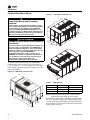
Unit Clearances, Curb Dimensions, and Dimensional
Data
Direct-Fired OAB Units
Unit Clearances
Curb Dimensions
Dimensional Data
WARNING
Combustible Materials!
Failure to maintain proper clearance between the unit
heat exchanger, vent surfaces and combustible
materials could cause a fire which could result in death
or serious injury or property damage. Refer to unit
nameplate and installation instructions for proper
clearances.
AVERTISSEMENT
Matériaux combustibles!
Tout manquement à l’obligation de maintenir une
distance appropriée entre l’échangeur de chaleur de
l’unité, les surfaces de ventilation et les matériaux
combustibles peut provoquer un incendie pouvant
résulter en des blessures corporelles graves, voire
mortelles, ou des dommages matériels. Reportez-vous
à la plaque signalétique de l’unité et aux instructions
d’installation pour connaître les distances appropriées.
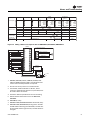
Figure 1. Typical installation clearances for direct-fired
OAB unit (in.)
84
72
36
36
48
36
Figure 2. Unit curb data for direct-fired OAB tons (in.)
Figure 3. Unit dimensional data for direct-fired OAB
(in.)
48.500
25.500
25.000
3.750
93.500
9.250
27.500
9.250
12.750
13.750
1.250
3.438
122.688
RETURN
SUPPLY
55.143
55.489
52.554
52.000
22.000
3.180
15.676
ELECTRIC
DISCONNECT
FRONT VIEW
12.979
18.149
144.349
126.200
97.000 29.200
RIGHT SIDE VIEW
3.250
12.000
SUPPLY
24.000
SUPPLY
16.000
26.500
RETURN
12.750
12.750
14.500
RETURN
32.450
22.000
4.498
THROUGH BASE
ELECTRIC
BOTTOM VIEW

Unit Clearances, Curb Dimensions, and Dimensional Data
OAU-SVX005C-EN 15
Direct-Fired OAG Units
Unit Clearances
Curb Dimensions
Dimensional Data
Figure 4. Typical installation clearances for direct-fired
OAG unit (in.)
Figure 5. Unit curb data for direct-fired OAG tons (in.)
72
84
36
36
48
36
70.500
22.625
21.000
8.750
15.000
25.000
RETURN
SUPPLY
53.000
8.750
117.500
23.375
35.375
11.875
Figure 6. Unit dimensional data for direct-fired OAG
(in.)
121.371
66.096
ELECTRIC
DISCONNECT
SWITCH
THROUGH BASE
ELECTRIC
74.000
17.323
33.751
121
3.078
GAS INLET
5.5852

16 OAU-SVX005C-EN
Unit Weight and Rigging
Unit Weight
WARNING
Heavy Objects!
Failure to follow instructions below or properly lift unit
could result in unit dropping and possibly crushing
operator/technician which could result in death or
serious injury, and equipment or property-only damage.
Ensure that all the lifting equipment used is properly
rated for the weight of the unit being lifted. Each of the
cables (chains or slings), hooks, and shackles used to
lift the unit must be capable of supporting the entire
weight of the unit. Lifting cables (chains or slings) may
not be of the same length. Adjust as necessary for even
unit lift.
AVERTISSEMENT
Objets lourds!
Le non-respect des instructions ci-dessous ou un levage
inapproprié de l’unité peut provoquer sa chute voire
écraser l’opérateur/le technicien, ce qui peut
occasionner des blessures graves voire mortelles, et
éventuellement endommager l’équipement ou
provoquer des dégâts matériels. Assurez-vous que
l’équipement de levage utilisé est adapté au poids de
l’unité à soulever. Chaque câble (chaîne ou élingue),
crochet ou manille utilisé pour le levage de l’unité doit
être assez robuste pour supporter le poids total de
l’unité. Les câbles, chaînes ou élingues de levage ne
doivent pas être de longueur identique. Procédez au
réglage afin de soulever l’unité de manière équilibrée.
WARNING
Improper Unit Lift!
Failure to properly lift unit could result in unit dropping
and possibly crushing operator/technician which could
result in death or serious injury, and equipment or
property-only damage. Test lift unit approximately
24 inches to verify proper center of gravity lift point. To
avoid dropping of unit, reposition lifting point if unit is
not level.
AVERTISSEMENT
Levage inapproprié de l’unité!
Le non-respect des instructions ci-dessous ou un levage
inapproprié de l’unité peut provoquer sa chute voire
écraser l’opérateur/le technicien, ce qui peut
occasionner des blessures graves voire mortelles, et
éventuellement endommager l’équipement ou
provoquer des dégâts matériels. Faites un test de
levage de l’unité d’environ 60 cm (24 po) afin de vérifier
que le point de levage correspond au centre de gravité
de l’appareil. Pour éviter une chute de celle-ci, ajustez
son point de levage si elle n’est pas à l’horizontale.
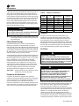
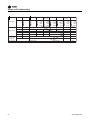
Table 1. Typical unit weight
Model Number
Operating Weight (lb)
Min Max
OABD036* 1655 1839
OABD048* 1655 1839
OABD060* 1655 1839
OABD072* 1695 1879
OABD084* 1695 1879
OABD096* 1695 1879
OABD108* 1736 1920
OAGD120* 2912 3198
OAGD144* 2912 3198
OAGD180* 2913 3199
OAGD210* 3062 3348
OAGD240* 3134 3439
OAGD264* 3135 3439
OAGD300* 3175 3489
OAGD360* 3186 3500
Note: Minimum and maximum weights vary widely due to the highly
configurable nature of the product.

Unit Weight and Rigging
OAU-SVX005C-EN 17
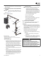
Rigging
Before proceeding, refer to Table 1, p. 16 for typical unit
operating weights and Figure 7, p. 17 for rigging drawing.
1. Rig the unit as shown in Figure 7, p. 17. Attach
adequate strength lifting slings to all four lifting
brackets in the unit base rail. Do not use cables, chains,
or slings except as shown.
2. Install a lifting bar, as shown in Figure 7, p. 17, to
protect the unit and to facilitate a uniform lift. The
minimum distance between the lifting hook and the
top of the unit should be 7 feet.
3. Test-lift the unit to ensure it is properly rigged and
balanced, make any necessary rigging adjustments.
4. Lift the unit and position it into place. Remove fork
pockets prior to setting on the curb.
5. Downflow units; align the base rail of the unit with the
curb rail while lowering the unit onto the curb. Make
sure that the gasket on the curb is not damaged while
positioning the unit.
Figure 7. Rigging
A
DETAIL A
SCALE 1 : 12
SCREW PIN SHACKLE
4 LOCATIONS
SPREADER BARS
6-point lift
(Model: Direct-fired OAB)
SPREADER
BARS
A
SCALE 1 : 12
DETAIL A
SCREW PIN SHACKLE
4 LOCATIONS
KCC
International Inc.
4-point lift
(Model: Direct-fired OAG)

18 OAU-SVX005C-EN
Installation
Ductwork
Elbows with turning vanes or splitters are recommended
to minimize air noise due to turbulence and to reduce static
pressure.
When attaching the ductwork to the unit, provide a water-
tight flexible connector at the unit to prevent operating
sounds from transmitting through the ductwork.
All outdoor ductwork between the unit and the structure
should be weather proofed after installation is completed.
Note: For sound consideration, cut holes in the roof deck
only for the ductwork penetrations. Do not cut out
the roof deck within the entire curb perimeter. All
duct work must be installed and connected to top of
roof curb before the unit is set on curb.
If a Curb Accessory Kit is not used:
1. Be sure to use flexible duct connections at the unit.
2. Gaskets must be installed around the curb perimeter
flange and the supply and return air opening flanges.
Note: For units will electric heat in the primary heating
position, refer to Figure 8.
General Unit Requirements
The checklist listed below is a summary of the steps
required to successfully install a commercial unit. This
checklist is intended to acquaint the installing personnel
with what is required in the installation process. It does
not replace the detailed instructions called out in
the applicable sections of this manual.
WARNING
Hazardous Service Procedures!
Failure to follow all precautions in this manual and on
the tags, stickers, and labels could result in death or
serious injury.
Technicians, in order to protect themselves from
potential electrical, mechanical, and chemical hazards,
MUST follow precautions in this manual and on the
tags, stickers, and labels, as well as the following
instructions: Unless specified otherwise, disconnect all
electrical power including remote disconnect and
discharge all energy storing devices such as capacitors
before servicing. Follow proper lockout/tagout
procedures to ensure the power can not be
inadvertently energized. When necessary to work with
live electrical components, have a qualified licensed
electrician or other individual who has been trained in
handling live electrical components perform these
tasks.
AVERTISSEMENT
Procédures d’entretien dangereuses!
Le non-respect de toutes les précautions contenues
dans ce manuel ainsi que sur les étiquettes et les
autocollants peut entraîner des blessures graves voire
mortelles.
Les techniciens, afin d’être protégés des éventuels
risques électriques, mécaniques et chimiques,
DOIVENT suivre les précautions contenues dans ce
manuel, sur les étiquettes et les autocollants, ainsi que
les instructions suivantes : Sauf indication contraire,
coupez toute l’alimentation électrique y compris les
disjoncteurs à distance et déchargez tous les dispositifs
de stockage d’énergie comme les condensateurs avant
l’entretien. Respectez les procédures de verrouillage et
d’étiquetage appropriées pour éviter tout risque de
remise sous tension accidentelle. S’il est nécessaire de
travailler avec des composants électriques sous
tension, demandez à un électricien qualifié et agréé ou
à une autre personne ayant la formation nécessaire
pour manipuler des composants électriques sous
tension d’exécuter ces tâches.
Figure 8.
Important: Bottom discharge units with open coil
electric heater in primary heat location
require discharge duct with 90° elbow. This
is a MANDATORY installation requirement.
Note: A minimum 48" of straight duct is required before
an elbow. This is a requirement for both vertical and
horizontal discharge regardless of heat type.
Check the unit for shipping damage and material
shortage. File a freight claim and notify appropriate
sales representative if damage or shortage is
discovered.
Verify that the unit nameplate model, options, and
voltage are correct.
Verify that the installation location of the unit will
provide the required clearance for proper operation.
Assemble and install the roof curb (if applicable).
Refer to the latest edition of the curb installers guide
that ships with each curb kit. Check curb for level
installation; if not level, shim as required.
Rigging unit (refer to “Unit Weight and Rigging,”
p. 16).
48" Minimum
Airflow

Installation
OAU-SVX005C-EN 19
Main Electrical Power Requirements
Note: All field-installed wiring must comply with NEC
and applicable local codes.
Condensate Drain Configuration
OAU units are selected based on dehumidification
capability. As such, condensate can form at a high rate.
Therefore, the OAU drain pan and condensate line are
sized and designed accordingly. However, an often-
overlooked element of proper condensate drainage is
proper P-Trap and drain line sizing and installation. An
incorrectly-designed and -installed P-Trap can restrict
condensate flow or cause water in the condensate drain
pan to “spit” or “geyser” which may cause condensate
overflow. Carefully install and trap the drain pan to ensure
adequate condensate removal under all conditions.
An evaporator condensate drain connection is provided
on the unit. Refer to Figure 11, p. 20 for the drain location.
A condensate trap must be installed at the unit due to the
drain connection being on the “negative pressure” side of
the fan. Install the P-Trap using the guidelines in Figure 9.
Pitch drain lines connected to P-Trap at least 1/2 inch for
every 10 feet of horizontal run to assure proper
condensate flow. Do not allow the horizontal run to sag
causing a possible double-trap condition which could
result in condensate backup due to “air lock”.
Filter Installation
Each unit ships with 2-inch permanent filters (mist
eliminators) along with the specified MERV-rated pleated
filters installed in the air inlet hood. The quantity of filters
is determined by unit size. Access to the filters is through
the hinged filter access panel on the air intake hood. Filter
type, size, and quantity are determined by selected filter
option and unit size.
Note: Do not operate the unit without filters. Pleated
filters are installed in the inlet hood in the direct-
fired unit.
Set the unit onto the curb; check for level.
Ensure unit-to-curb seal is tight and without buckles
or cracks.
Install and connect proper condensate drain line to
the evaporator condensate pan drain connection (see
Figure 9, p. 19).
Verify that the power supply complies with the unit
nameplate specifications.
Inspect all control panel components; tighten any
loose connections.
Connect properly sized and protected power supply
wiring to a field-supplied/-installed disconnect switch
and to the main power terminal block (HTB1) in the
unit control panel.
Connect properly-sized earth ground.
Figure 9. Condensate trap installation
D = Pipe diameter (1 in.)
H = Internal static pressure (in wg) +1 in.
J = H x 0.5
L = H + J +D
Notes:
1. Pitch drain at least 1/2 in. per 10 ft horizontal run.
2. Condensate drain pan will not drain properly if P-trap is not primed
and of adequate height to allow for cabinet operating negative
pressure.
WARNING
Do Not Install Filters or Flammable
Components Downstream of Direct-Fired
Burner!
Installing filters or flammable components downstream
of the direct-fired burner could cause a fire hazard and
result in death or serious injury.
AVERTISSEMENT
N’installez pas de filtre ou de composant
inflammable en aval du brûleur à feu
direct!
L’installation de filtres ou de composants inflammables
en aval du brûleur à feu direct peut provoquer un risque
d’incendie et résulter en des blessures graves, voire
mortelles..
D" NPT FEMALE
CONNECTOR
CLEANOUT PLUG
D = PIPE DIAMETER
H = INTERNAL STATIC PRESSURE (IN W.G.) + 1"
J = H * 0.5
L = H + J + D

Installation
20 OAU-SVX005C-EN
Field Installed Power Wiring
An overall dimensional layout for the standard field
installed wiring entrance into the unit is illustrated in
Figure 10 and Figure 11. To ensure that the unit’s supply
power wiring is properly sized and installed, refer to the
following guidelines.
Note: All field installed wiring must conform to NEC
guidelines as well as State and Local codes.
Verify that the power supply available is compatible with
the unit’s nameplate ratings. The available supply power
must be within 10 percent of the rated voltage stamped on
the nameplate. Use only copper conductors to connect the
power supply to the unit.
WARNING
Proper Field Wiring and Grounding
Required!
Failure to follow code could result in death or serious
injury. All field wiring MUST be performed by qualified
personnel. Improperly installed and grounded field
wiring poses FIRE and ELECTROCUTION hazards. To
avoid these hazards, you MUST follow requirements for
field wiring installation and grounding as described in
NEC and your local/state electrical codes.
AVERTISSEMENT
Câblage sur site et mise à la terre corrects
nécessaires!
Le non-respect de la réglementation peut entraîner des
blessures graves, voire mortelles. Il est IMPÉRATIF de
confier l’ensemble du câblage sur site à un électricien
qualifié. Un câblage sur site mal installé ou mal mis à la
terre constitue des risques D’INCENDIE et
D’ÉLECTROCUTION. Pour éviter ces risques, il est
IMPÉRATIF de respecter les obligations en matière de
pose de câblage sur site et de mise à la terre tel que
stipulé dans les règles du NEC et dans les
réglementations électriques locales/nationales.
Figure 10. OAB utility connections (in.)
ELECTRIC
DISCONNECT
SWITCH
GAS INLET
1.25 IN. MPT
CONDENSATE
DRAIN
0.5 IN. FPT
18.051
118.701
10.672
6.854
62.203
7.024
22.002
6.901
54.179
Figure 11. OAG utility connections (in.)
Table 2. OAB/OAG unit
Maximum MBh Burner Size (in.) Pipe Connection (in.)
300 6 1
660 12 1
814 18 1-1/4
121.371
66.096
ELECTRIC
DISCONNECT
SWITCH
THROUGH BASE
ELECTRIC
74.000
17.323
33.751
121
3.078
GAS INLET
5.5852
6.000
62.268
5.044
HEIGHT OF INLET
TO BASE
La page est en cours de chargement...
La page est en cours de chargement...
La page est en cours de chargement...
La page est en cours de chargement...
La page est en cours de chargement...
La page est en cours de chargement...
La page est en cours de chargement...
La page est en cours de chargement...
La page est en cours de chargement...
La page est en cours de chargement...
La page est en cours de chargement...
La page est en cours de chargement...
La page est en cours de chargement...
La page est en cours de chargement...
La page est en cours de chargement...
La page est en cours de chargement...
La page est en cours de chargement...
La page est en cours de chargement...
La page est en cours de chargement...
La page est en cours de chargement...
La page est en cours de chargement...
La page est en cours de chargement...
La page est en cours de chargement...
La page est en cours de chargement...
La page est en cours de chargement...
La page est en cours de chargement...
La page est en cours de chargement...
La page est en cours de chargement...
La page est en cours de chargement...
La page est en cours de chargement...
La page est en cours de chargement...
La page est en cours de chargement...
La page est en cours de chargement...
La page est en cours de chargement...
La page est en cours de chargement...
La page est en cours de chargement...
La page est en cours de chargement...
La page est en cours de chargement...
La page est en cours de chargement...
La page est en cours de chargement...
-
 1
1
-
 2
2
-
 3
3
-
 4
4
-
 5
5
-
 6
6
-
 7
7
-
 8
8
-
 9
9
-
 10
10
-
 11
11
-
 12
12
-
 13
13
-
 14
14
-
 15
15
-
 16
16
-
 17
17
-
 18
18
-
 19
19
-
 20
20
-
 21
21
-
 22
22
-
 23
23
-
 24
24
-
 25
25
-
 26
26
-
 27
27
-
 28
28
-
 29
29
-
 30
30
-
 31
31
-
 32
32
-
 33
33
-
 34
34
-
 35
35
-
 36
36
-
 37
37
-
 38
38
-
 39
39
-
 40
40
-
 41
41
-
 42
42
-
 43
43
-
 44
44
-
 45
45
-
 46
46
-
 47
47
-
 48
48
-
 49
49
-
 50
50
-
 51
51
-
 52
52
-
 53
53
-
 54
54
-
 55
55
-
 56
56
-
 57
57
-
 58
58
-
 59
59
-
 60
60


Trane Horizon OAGD180 Series Installation, Operation and Maintenance Manual
- Catégorie
- Pompes à chaleur
- Taper
- Installation, Operation and Maintenance Manual
dans d''autres langues
- English: Trane Horizon OAGD180 Series
Documents connexes
Autres documents
-
STA-RITE MIB0715B, MIB0715S Intelliboost Le manuel du propriétaire
-
Makita PM7650H Manuel utilisateur
-
GE Caliber Mode d'emploi
-
ClimateMaster CP, MH, MV, PDE, EH, EV Install Manual
-
Ingersoll-Rand R55 Manuel utilisateur
-
 TPI 2600 Series Guide d'installation
-
Maytag C7B(A,H)M0 Guide d'installation
-
Greenheck 453905 TAUD/TAUB Mode d'emploi
-
-
Airwell DLS VAV SYSTEM Installation And Operation Instructions Manual
