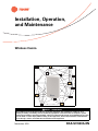
Trane Wireless Comm Installation, Operation and Maintenance Manual
- Taper
- Installation, Operation and Maintenance Manual

SAFETY WARNING
Only qualified personnel should install and service the equipment. The installation, starting up, and
servicing of heating, ventilating, and air-conditioning equipment can be hazardous and requires specific
knowledge and training. Improperly installed, adjusted or altered equipment by an unqualified person could
result in death or serious injury. When working on the equipment, observe all precautions in the literature
and on the tags, stickers, and labels that are attached to the equipment.
Wireless Comm
November 2012 BAS-SVX40A-EN
WCI
WCI
WCI
WCI
WCI
WCI
WCI
WCI
WCI
WCI
WCI
WCI
WCI
WCI
Installation, Operation,
and Maintenance

© 2012 Trane All rights reserved BAS-SVX40A-EN
Introduction
Read this manual thoroughly before operating or servicing
this unit.
Warnings, Cautions, and Notices
Safety advisories appear throughout this manual as
required. Your personal safety and the proper operation of
this machine depend upon the strict observance of these
precautions.
Important Environmental Concerns
Scientific research has shown that certain man-made
chemicals can affect the earth’s naturally occurring
stratospheric ozone layer when released to the
atmosphere. In particular, several of the identified
chemicals that may affect the ozone layer are refrigerants
that contain Chlorine, Fluorine and Carbon (CFCs) and
those containing Hydrogen, Chlorine, Fluorine and
Carbon (HCFCs). Not all refrigerants containing these
compounds have the same potential impact to the
environment. Trane advocates the responsible handling of
all refrigerants-including industry replacements for CFCs
such as HCFCs and HFCs.
Important Responsible Refrigerant Practices
Trane believes that responsible refrigerant practices are
important to the environment, our customers, and the air
conditioning industry. All technicians who handle
refrigerants must be certified. The Federal Clean Air Act
(Section 608) sets forth the requirements for handling,
reclaiming, recovering and recycling of certain
refrigerants and the equipment that is used in these
service procedures. In addition, some states or
municipalities may have additional requirements that
must also be adhered to for responsible management of
refrigerants. Know the applicable laws and follow them.
Copyright
This document and the information in it are the property of
Trane and may not be used or reproduced in whole or in
part, without the written permission of Trane. Trane
reserves the right to revise this publication at any time and
to make changes to its content without obligation to notify
any person of such revision or change.
Trademarks
All trademarks referenced in this document are the
trademarks of their respective owners.
The three types of advisories are defined as follows:
WARNING
Indicates a potentially hazardous
situation which, if not avoided, could
result in death or serious injury.
CAUTIONs
Indicates a potentially hazardous
situation which, if not avoided, could
result in minor or moderate injury. It
could also be used to alert against
unsafe practices.
NOTICE:
Indicates a situation that could result in
equipment or property-damage only.
WARNING
Proper Field Wiring and Grounding
Required!
Failure to follow code could result in death or serious
injury. All field wiring MUST be performed by qualified
personnel. Improperly installed and grounded field
wiring poses FIRE and ELECTROCUTION hazards. To
avoid these hazards, you MUST follow requirements for
field wiring installation and grounding as described in
NEC and your local/state electrical codes.
WARNING
Personal Protective Equipment (PPE)
Required!
Failure to wear proper PPE for the job being undertaken
could result in death or serious injury. Technicians, in
order to protect themselves from potential electrical,
mechanical, and chemical hazards, MUST follow
precautions in this manual and on the tags, stickers,
and labels, as well as the instructions below:
• Before installing/servicing this unit, technicians
MUST put on all PPE recommended for the work
being undertaken. ALWAYS refer to appropriate
MSDS sheets and OSHA guidelines for proper PPE.
• When working with or around hazardous chemicals,
ALWAYS refer to the appropriate MSDS sheets and
OSHA guidelines for information on allowable
personal exposure levels, proper respiratory
protection, and handling recommendations.
• If there is a risk of arc or flash, technicians MUST put
on all PPE in accordance with NFPA 70E or other
country-specific requirements for arc flash
protection, PRIOR to servicing the unit.

Table of Contents
BAS-SVX40A-EN 3
Introduction . . . . . . . . . . . . . . . . . . . . . . . . . . . . . . . . . . . . . . . . . . . . . . . . . . . . . . . . . . . . 2
Warnings, Cautions, and Notices . . . . . . . . . . . . . . . . . . . . . . . . . . . . . . . . . . . . . 2
Important Environmental Concerns . . . . . . . . . . . . . . . . . . . . . . . . . . . . . . . 2
Important Responsible Refrigerant Practices . . . . . . . . . . . . . . . . . . . . . . . 2
General Information . . . . . . . . . . . . . . . . . . . . . . . . . . . . . . . . . . . . . . . . . . . . . . . . . . . . 5
Product Description . . . . . . . . . . . . . . . . . . . . . . . . . . . . . . . . . . . . . . . . . . . . . . . . 5
Dimensions . . . . . . . . . . . . . . . . . . . . . . . . . . . . . . . . . . . . . . . . . . . . . . . . . . . . . . . 6
Specifications and Agency Compliance . . . . . . . . . . . . . . . . . . . . . . . . . . . . . . . 7
Location Considerations . . . . . . . . . . . . . . . . . . . . . . . . . . . . . . . . . . . . . . . . . . . . . . . . . 9
Maximum Wire Length . . . . . . . . . . . . . . . . . . . . . . . . . . . . . . . . . . . . . . . . . 9
Installation Locations . . . . . . . . . . . . . . . . . . . . . . . . . . . . . . . . . . . . . . . . . . 9
Coordinator Location . . . . . . . . . . . . . . . . . . . . . . . . . . . . . . . . . . . . . . . . . . 9
WCI Addressing . . . . . . . . . . . . . . . . . . . . . . . . . . . . . . . . . . . . . . . . . . . . . . . . . . . . . . . 10
Setting Network Communication Addressing . . . . . . . . . . . . . . . . . . . . . . . . . 10
Setting Wireless Zone Sensor Receiver Addressing . . . . . . . . . . . . . . . . . . . 11
Mounting and Wiring the WCI . . . . . . . . . . . . . . . . . . . . . . . . . . . . . . . . . . . . . . . . . . 12
Controller Applications . . . . . . . . . . . . . . . . . . . . . . . . . . . . . . . . . . . . . . . . . . . . 12
Repeater Applications . . . . . . . . . . . . . . . . . . . . . . . . . . . . . . . . . . . . . . . . . . . . . 16
Establishing the Network . . . . . . . . . . . . . . . . . . . . . . . . . . . . . . . . . . . . . . . . . . . . . . . 17
WCI LEDs and Buttons . . . . . . . . . . . . . . . . . . . . . . . . . . . . . . . . . . . . . . . . . . . . . 17
Three Ways to Establish a Wireless Network . . . . . . . . . . . . . . . . . . . . . . . . . 19
Establishing the Network After Tracer SC Installation . . . . . . . . . . . . . . . 19
Establishing the Network Prior to Tracer SC Installation or Without Tracer
SC Installation . . . . . . . . . . . . . . . . . . . . . . . . . . . . . . . . . . . . . . . . . . . . . . . 19
WCIs as Zone Sensor Receivers . . . . . . . . . . . . . . . . . . . . . . . . . . . . . . . . . . . . . 20
Modifying the Network . . . . . . . . . . . . . . . . . . . . . . . . . . . . . . . . . . . . . . . . . . . . . . . . . 22
Adding Additional WCIs to an Existing Network . . . . . . . . . . . . . . . . . . . . . . . 22
Adding Additional Coordinators to a Tracer SC . . . . . . . . . . . . . . . . . . . . . . . 22
Removing a WCI from a Network . . . . . . . . . . . . . . . . . . . . . . . . . . . . . . . . . . . 23
Replacing a WCI on a Network . . . . . . . . . . . . . . . . . . . . . . . . . . . . . . . . . . . . . . 23
Closing the Network . . . . . . . . . . . . . . . . . . . . . . . . . . . . . . . . . . . . . . . . . . . . . . . 23
Disbanding a Network . . . . . . . . . . . . . . . . . . . . . . . . . . . . . . . . . . . . . . . . . . . . . 23
Troubleshooting . . . . . . . . . . . . . . . . . . . . . . . . . . . . . . . . . . . . . . . . . . . . . . . . . . . . . . . 24
WCI does not join network . . . . . . . . . . . . . . . . . . . . . . . . . . . . . . . . . . . . . 24
Tracer SC does not communicate with WCI . . . . . . . . . . . . . . . . . . . . . . 24
Sensor does not communicate with WCI . . . . . . . . . . . . . . . . . . . . . . . . . 24
No communication . . . . . . . . . . . . . . . . . . . . . . . . . . . . . . . . . . . . . . . . . . . 25

4 BAS-SVX40A-EN
Slow communication . . . . . . . . . . . . . . . . . . . . . . . . . . . . . . . . . . . . . . . . . 25
Replacing a Failed WCI . . . . . . . . . . . . . . . . . . . . . . . . . . . . . . . . . . . . . . . . 25
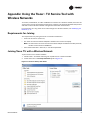
Appendix: Using the Tracer™ TU Service Tool with Wireless Networks . . . . 27
Requirements for Joining . . . . . . . . . . . . . . . . . . . . . . . . . . . . . . . . . . . . . . . . . . 27
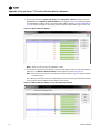
Joining Tracer TU with a Wireless Network . . . . . . . . . . . . . . . . . . . . . . . . . . 27
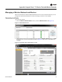
Managing a Wireless Network and Devices . . . . . . . . . . . . . . . . . . . . . . . . . . . 29
Connecting to a Device . . . . . . . . . . . . . . . . . . . . . . . . . . . . . . . . . . . . . . . . 29
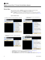
Wireless Menu . . . . . . . . . . . . . . . . . . . . . . . . . . . . . . . . . . . . . . . . . . . . . . . 30
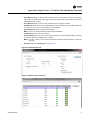
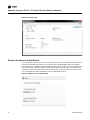
Wireless Zone Sensor Enable/Disable . . . . . . . . . . . . . . . . . . . . . . . . . . . . 32

BAS-SVX40A-EN 5
General Information
This section provides general information about the wireless Comm interface (WCI).
Product Description
The Trane® Wireless Comm Interface (WCI) enables wireless communication between system
controls, unit controls, and wireless sensors for the new generation of Trane control products. The
WCI replaces the need for communication wire in all system applications.
Types of Devices Supported by the WCI
• Tracer™ SC system controller
• Tracer™ UC400 programmable controller
• Tracer™ UC600 programmable controller
• BCI-I: BACnet Communications Interface for IntelliPak™ systems
• BCI-R: BACnet Communications Interface for ReliaTel™ systems
• Tracer™ TU
• Wireless zone sensors
Quantity of WCIs per Network
Each Trane wireless network can have a total of 31 WCIs (30 member WCIs plus 1 coordinator WCI).
Each network requires one WCI to function as network coordinator.
Quantity of Networks per Tracer SC
A Tracer SC can support up to 8 wireless networks.
Note: For information about installing a WCI on a Tracer SC, see “Mounting and Wiring the WCI,”
p. 12 and Figure 6, p. 14.
Automatic Network Formation
When a WCI is connected to a Tracer SC, it is auto-assigned as the coordinator. To enable the
coordinator, Tracer SC must be configured for wireless communication. The coordinator WCI
opens the network to allow all WCIs having matching addresses to automatically join the network.
If no Tracer SC is present, a centrally located WCI must be designated to act as the coordinator. You
can manually set the coordinator WCI so all WCIs having matching addresses automatically join
the network.
Note: For additional information, see “Establishing the Network,” p. 17.
Wireless Zone Sensors
The WCI also communicates with Trane wireless zone sensors, eliminating the need for analog
receivers.
Wired Zone Sensors
Systems using Wireless Comm can also use wired zone sensors.
Network Security
The WCI uses standard ZigBee™ Building Automation security practices by the use of AES128
encryption, keys, and device authentication.
Part Numbers
Available models are listed by part number:
Part number Description
X13790901 Includes wiring harness and screws. For field-mount applications.
X13790902 For flush-mount applications. (Wiring harness not included.)

6 BAS-SVX40A-EN
General Information
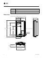
Dimensions
The dimensions of the WCI enclosure are as follows:
X13790903
Bulk version of X13790901, no wiring harness, no installation instructions. For factory ordering
in bulk.
X13790904
Bulk version of X13790902, no wiring harness, no installation instructions. For factory ordering
in bulk.
X13641194 Outdoor enclosure to protect WCI from harsh environments or wet indoor environments.
Part number Description
0.650 in. (16.50 mm)
2.896 in. (73.55 mm)
3.386 in. (86.00 mm)
2.480 in. (63.00 mm)
1.344 in. (34.14 mm)
0.236 in. (6.00 mm)
1.419 in. (36.03 mm)
4.677 in. (118.80 mm)
0.118 in. (3.00 mm)
2.620 in. (66.55 mm)
0.581 in. (14.76 mm)
R0.71 in. (R1.80 mm) TYP

BAS-SVX40A-EN 7
General Information
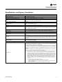
Specifications and Agency Compliance
Specifications
Operating temperature -40 to 158ºF (-40 to 70ºC)
Storage temperature -40 to 185ºF (-40 to 85°C)
Storage and operating humidity range 5% to 95% relative humidity (RH), non-condensing
Voltage
24 Vac/Vdc nominal ± 10%
If using 24 Vac, polarity must be maintained.
Receiver power consumption <2.5 VA
Housing material
Polycarbonate/ABS (suitable for plenum mounting), UV protected,
UL 94: 5 VA flammability rating
Mounting 3.2 in (83 mm) with 2 supplied mounting screws
Range
(a)
Open range: 2,500 ft (762 m) with packet error rate of 2%
Indoor: Typical range is 200 ft (61 mm); actual range is dependent on the environment.
See BAS-SVX55 for more detail.
Output power North America: 100 mW
Radio frequency 2.4 GHz (IEEE Std 802.15.4-2003 compliant) (2405–2480 MHz, 5 MHz spacing)
Radio channels 16
Address range
Group 0–8
Network 1–9
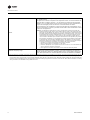
Mounting
Fits a standard 2 in. by 4 in. junction box (vertical mount only). Mounting holes are spaced
3.2 in. (83 mm) apart on vertical center line. Includes mounting screws for junction box
or wall anchors for sheet-rock walls. Overall dimensions: 2.9 in. (74 mm) by 4.7 in.
(119 mm)
Wireless protocol
ZigBee PRO—ZigBee Building Automation Profile, ANSI/ASHRAE Standard 135-2008
Addendum q (BACnet™/ZigBee)
Agency compliance
United States
UL listed: UL 94, 5 VA flammability rating and UL916.
Energy Management Equipment FCC CFR47, Sec. 15.247 & subpart E, Digital Modulation
Transmission with no SAR (FCC ID: TPF-251701).
This device complies with part 15 of the FCC Rules. Operation is subject to the following
two conditions: (1) This device may not cause harmful interference, and (2) this device
must accept any interference received, including interference that may cause undesired
operation.
Changes or modifications not expressly approved by the manufacturer for compliance
could void the user’s authority to operate the equipment.
Note: This equipment has been tested and found to comply with the limits for a Class B digital
device, pursuant to part 15 of the FCC Rules. These limits are designed to provide
reasonable protection against harmful interference in a residential installation. This
equipment generates, uses and can radiate radio frequency energy and, if not installed
and used in accordance with the instructions, may cause harmful interference to radio
communications. However, there is no guarantee that interference will not occur in a
particular installation. If this equipment does cause harmful interference to radio or
television reception, which can be determined by turning the equipment off and on, the
user is encouraged to try to correct the interference by one or more of the following
measures:
• Reorient or relocate the receiving antenna.
• Increase the separation between the equipment and receiver.
• Connect the equipment into an outlet on a circuit different from that to which the
receiver is connected.
• Consult the dealer or an experienced radio/TV technician for help.

8 BAS-SVX40A-EN
General Information
Canada
CSA-C22.2 No. 205-M1983 Signal Equipment Industry Canada
(IC: 6178A-251701)
Cet appareil est conforme à la partie 15 du règlement du FCC. Son fonctionnement fait
l’objet des deux conditions suivantes : (1) Cet appareil ne produit pas de brouillages
nuisibles, et (2) cet appareil doit pouvoir recevoir n’importe quel type d’interférence, y
compris les brouillages pouvant occasionner un fonctionnement non désiré.
Les changements et les modifications n’ayant pas été approuvés expressément par le
fabricant comme étant conformes, pourraient rendre nulle le droit de l’utilisateur à faire
fonctionner cet équipement.
Remarque: Cet équipement a été testé et reconnu comme étant conforme aux limites des
appareils numériques de classe B, tel qu’indiqué dans la partie 15 du règlement du FCC.
Ces limites ont été établies afin de fournir un niveau de protection raisonnable contre le
brouillage nuisible dans les installations résidentielles. Cet appareil produit, utilise, et peut
aussi émettre des fréquences radioélectriques. Si celui-ci n’est pas installé et utilisé
conformément aux instructions, il peut provoquer des brouillages nuisibles dans les
communications radioélectriques. L’absence d’interférence n’est cependant pas garantie
dans toutes les installations. Si cet équipement provoque des brouillages nuisibles dans
la réception des communications radioélectriques ou de télévision (ceci pouvant être
déterminé en allumant et en éteignant l’équipement), l’utilisateur est encouragé à essayer
de corriger l’interférence en utilisant un ou plusieurs des moyens suivants :
• Réorienter ou changer l’emplacement de l’antenne réceptrice.
• Éloigner l’équipement et le récepteur l’un de l’autre.
• Brancher l’équipement à une prise de courant se trouvant sur un circuit différent de
celui sur lequel le récepteur est branché.
• Faire appel aux services du fournisseur ou d’un technicien radio/TV qualifié.
IEEE/radio frequency range
IEEE 802.15.4-2003, IEEE Standard for Information Technology—Telecommunications
and information exchange between systems—Local and metropolitan area networks—
Specific requirements, Part 15.4: Wireless Medium Access Control (MAC) and Physical
Layer (PHY) Specifications for Low Rate Wireless Personal Area Networks (LR-WPANs)
(a) Range values are estimated transmission distances for satisfactory operation. Actual distance is job specific and must be determined during site eval-
uation. Placement of the WCI is critical to proper system operation. In most general office space installations, distance is not the limiting factor for
proper signal quality. Signal quality is more greatly affected by walls, barriers, and general clutter. Note that sheetrock walls and ceiling tiles offer little
restriction to the propagation of the radio signal throughout the building as opposed to concrete or metal barriers. More details information, including
wiring schematics, are available at http://www.trane.com.

BAS-SVX40A-EN 9
Location Considerations
To provide the best signal strength between associated wireless devices and to reduce the number
of WCIs needed for an application, mount WCIs in direct, unobstructed, line-of-sight paths. Locate
WCIs so that the number of metal and concrete barriers between pairs of devices is minimal. In
general, sheetrock walls and ceiling tiles are not of concern.
For more detailed information about WCI placement, see the Wireless Comm Network Design Best
Practices Guide (BAS-SVX55).
The WCI produces very low levels of electromagnetic (RF) energy. To avoid exposure, keep the WCI a minimum of 8
in. (20 cm) from your body.
Maximum Wire Length
The maximum wire length between the WCI and its power source is 656 ft (200 m).
Installation Locations
Unit controller
For a unit controller installation, the most typical WCI mounting location is on the sheet metal
enclosure of the unit controller or HVAC equipment housing.
Rooftop or air-handling unit
The recommended location is outside of the rooftup or air-handling unit. In outdoor locations, the
WCI should be mounted inside of a plastic enclosure suitable for outdoor use. Kele PS 1811-9 and
TK 1811 are recommended models.
Repeaters overcome out-of-radio-range issues
A WCI can be installed to function as a repeater to bridge the signal between a WCI that is out of
the radio range of the other WCIs (see “Repeater Applications,” p. 16). When choosing a location
for a repeater WCI, consider the availability of a 24 Vac/Vdc power source to meet its power
requirement.
Coordinator Location
For optimum network performance and reliability, the coordinator WCI should be centrally located
within the network. See the Wireless Comm Network Design Best Practices Guide (BAS-SVX55) for
more detail.
CAUTION
Avoid exposure to electromagnetic energy!
The WCI produces very low levels of electromagnetic energy. To avoid exposure, keep the WCI
a minimum of 8 in. (20 cm) from your body.
Risque d’exposition à l’énergie électromagnétique!
L’interface de communication (WCI) sans fil produit de l'énergie électromagnétique de très bas
niveau. Afin d'empêcher toute exposition, maintenez-la à au moins 20 cm (8 pouces) de votre
corps.

10 BAS-SVX40A-EN
WCI Addressing
This section describes the WCI addressing scheme and procedure. WCIs can be ordered either pre-
addressed or without addresses. Verify pre-addressed WCI prior to installation.
Setting Network Communication Addressing
Important: Addresses must be set on WCIs before applying power to them.
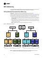
Follow this procedure to set the WCI address for network communication. Figure 1 illustrates the
addressing scheme used for WCIs. The illustration shows four networks and two Tracer SCs, with
each Tracer SC communicating on two networks. See Table 1, p. 11 for address settings.
1. Set the left (GRP) rotary address switch for each WCI that is in the same Tracer SC group to an
identical number. (A Tracer SC group refers to all of the networks that communicate with the
same Tracer SC.)
2. Set the right (NET) rotary address switch for each WCI that is to be on the same network to an
identical number. If there are multiple networks in a Tracer SC group, each network in that group
must have a unique number.
Note: The NET address must match the wireless link on Tracer SC.
Figure 1. WCI addressing example
Note: The Wireless Comm Network Design Best Practices Guide (BAS-SVX55) provides an
example of network addressing from a floor plan perspective.
UC/BCI
Tracer SC-1
UC/BCI
WCI WCI
GRP NET
NET
GRP NET
1
11
11
WCI
WCI WCI
GRP NET
GRP
NET
GRP NET
12
12
12
WCI
WCI WCI
GRP NET
GRP
NET
GRP NET
21
21
21
WCI
WCI WCI
GRP NET
GRP
NET
GRP NET
22
22
22
WCI
UC/BCI UC/BCI
UC/BCI UC/BCI UC/BCI UC/BCI
GRP
1
Tracer SC-2
Network
Network
Network
Network
Tracer SC Group
Tracer SC Group
1
2
3
4
5
6
7
8
9
0
NET
GRP
1
2
3
4
5
6
7
8
9
0

BAS-SVX40A-EN 11
WCI Addressing
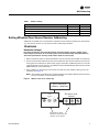
Setting Wireless Zone Sensor Receiver Addressing
A WCI that is installed on a unit controller as a wireless communication interface can also function
as a zone sensor receiver. To set up this function, follow this procedure:
WARNING
Hazardous voltage!
Disconnect all electric power, including remote disconnects before servicing. Follow proper
lockout/tagout procedures to ensure that power cannot be inadvertently energized. Failure to
disconnect power before servicing could result in death or serious injury.
1. Make sure that AC power is disconnected from the unit controller that the WCI is installed on.
2. Choose unit controller and wireless zone sensor addresses so that no two wireless zone sensors
sharing the same address are within radio range of each other. (Addresses above 127 may be
used for Wireless Comm systems; see Wireless Comm Network Design Best Practices Guide
(BAS-SVX55) for more information.)
3. Set the address on the wireless zone sensor to match the rotary address setting on the unit
controller (see
Figure 2).
Note: The numbers on the WCI rotary address switches are oriented differently from those on
the unit controllers, as the illustration indicates.
Figure 2. Wireless zone sensor addressing
Table 1. Address settings
Function/Purpose GRP NET
Trane BACnet communication and receiver for sensor 0–8 1–8
Receiver for sensor only 1–9 0
Return to default configuration 0 0
Future use 91–8
1
2
2
3
4
5
6
7
8
9
0
1
3
4
5
6
7
1
2
3
4
5
6
7
8
9
0
8
9
0
UC
Wireless zone
sensor
Match to UC
1
2
3
5
6
7
8
9
0
1
2
3
4
5
6
7
8
9
0
1
2
3
4
5
6
7
8
9
0
ADDRESS
4
WCI as zone
sensor receiver
Be careful to match
addresses rather than the
direction of the arrows.

12 BAS-SVX40A-EN
Mounting and Wiring the WCI
Follow these instructions:
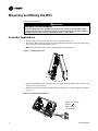
Controller Applications
1. Remove power from the controller that is to have the WCI wired to it.
2. Remove the WCI cover by firmly pressing the thumb tab at the bottom of the cover and pulling
the cover away from the back plate (
Figure 3).
Note: If present, remove the security screw before removing the cover.
Figure 3. Removing the cover
3. Secure the backplate to the mounting surface using appropriate hardware. (M3.5 x 20 mm self-
drilling screws are provided.)
4. Attach the 4-connector screw terminal block on the wiring harness to the receptacle on the WCI
(
Figure 4).
Figure 4. Connecting wiring harness
WARNING
Hazardous Service Procedures!
Disconnect all electric power, including remote disconnects before servicing. Follow proper
lockout/tagout procedures to ensure the power can not be inadvertently energized. Failure to
disconnect power before servicing could result in death or serious injury.
Blue = LINK +
Gray = LINK -
Black =
Red = +24 Vdc/ac

BAS-SVX40A-EN 13
Mounting and Wiring the WCI
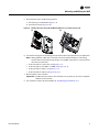
5. Route the wires from the WCI through either:
a. The opening in the back plate (Figure 5, a).
b. The bottom exit port (Figure 5, b).
Figure 5. Routing the wires through the WCI backplate (a) or bottom exit port (b)
6. Connect the wiring harness according to the illustration that is appropriate for your application:
Note: Wiring between a WCI and a controller cannot exceed 656 ft (200 m). If the wiring
harness does not provide enough length, use 18 AWG (24 pF/ft max.) communication
wire (Trane purple wire).
• To wire the WCI to a Tracer SC, see Figure 6, p. 14.
• To wire the WCI to a UC400 or a UC600, see Figure 7, p. 14.
• To wire the WCI to a BCI-I, see Figure 9, p. 15.
• To wire the WCI to a BCI-R, see Figure 10, p. 15.
7. Restore power to the controller.
Important: The WCI must be wired to the controller prior to power up in order to establish
network communication.
8. The network is ready to be formed. Refer to “Establishing the Network,” p. 17.
(a)
(b)

14 BAS-SVX40A-EN
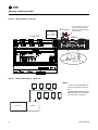
Mounting and Wiring the WCI
Figure 6. Wiring the WCI to a Tracer SC
Figure 7. Wiring multiple WCIs to a Tracer SC
Tracer SC
PM014
WCI wiring
LINK +
LINK –
+ 24VDC
IMC– IMC+
Grou nd 2 4 Vd c
Gray = LINK -
Blue = LINK +
Black = Ground
Red = 24 Vdc
Connect both 2-connector
screw terminal blocks to
either of the IMC terminals
on the PM014.
WCI WCIWCIWCI
WCI WCIWCIWCI
Tracer SC
PM014
Notes:
• A maximum of eight WCIs can
be daisy-chained to the Tracer
SC.
• Use both IMC terminals on the
PM014 for wiring multiple WCIs
(see the detail in Figure 6).

BAS-SVX40A-EN 15
Mounting and Wiring the WCI
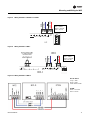
Figure 8. Wiring the WCI to a UC400 or a UC600
Figure 9. Wiring the WCI to a BCI-I
Figure 10. Wiring the WCI to a BCI-R
+
24
VDC
IM
C
LINK
IMC
LINK+
LINK-
+24 Vdc
UC
Gray = LINK -
Blue = LINK+
Black = Ground
Red = 24 Vdc
VAC
24
BI
1
BI
2
BI
3
LINK
IMC
+
24
VDC
IM
C
Jumper
LINK -
LINK +
+24 Vdc
WCI
BCI-I
Attach jumper at BI1
to enable wireless
communication.
Gray = LINK -
Blue = LINK +
Black = Ground
Red = 24 Vdc
BCI-R Board
Gray = IMC–
Blue = IMC+
Slide switch to IMC
RTRM
Black = Ground
Red = 24 Vac

16 BAS-SVX40A-EN
Mounting and Wiring the WCI
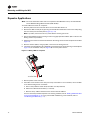
Repeater Applications
Note: For more information about the use of repeaters with Wireless Comm, see the Wireless
Comm Network Design Best Practices (BAS-SVX55).
To install a WCI to function as a repeater:
1. Remove power from the controller that is to have the WCI wired to it.
2. Remove the WCI cover by firmly pressing the thumb tab at the bottom of the cover and pulling
the cover away from the back plate (Figure 3, p. 12).
Note: If present, remove the security screw before removing the cover.
3. Secure the backplate to the mounting surface using appropriate hardware. (M3.5 x 20 mm self-
drilling screws are provided.)
4. Attach the 4-connector screw terminal block on the wiring harness to the receptacle on the WCI
(Figure 4).
5. Remove the blue (IMC+) and gray (IMC-) wires from the wiring harness.
6. Connect the red (24 Vdc/Vac) wire and black (ground) wire through the opening in the backplate
(Figure 5a) or the bottom exit port (Figure 5b) to a 24 V power source.
Figure 11. Wiring a WCI as a repeater
7. Restore power to the controller.
8. If the WCI communication wire was previously connected to a unit controller, return the WCI
to its default configuration as follows:
a. Set its rotary address switch to 0,0 (the WCI must be powered).
b. Observe its LEDs blink On briefly (<1 second).
c. Reset its rotary address switches to the correct network address.
You are now ready to add the repeater to an existing network (refer to “Adding Additional WCIs
to an Existing Network,” p. 22) or to proceed with establishing a new network (refer to
“Establishing the Network,” p. 17).
+24 VDC/VAC

BAS-SVX40A-EN 17
Establishing the Network
When all aspects of hardware installation are complete, you are ready to power up the system and
establish the network. Before you perform these tasks, ensure that all work described in the “WCI
Addressing,” p. 10 and “Mounting and Wiring the WCI,” p. 12 sections are complete.
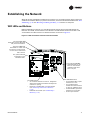
WCI LEDs and Buttons
Before establishing a network, you should be familiar with the layout of the WCI board, the
behavior of its LEDs, and the function of its buttons. The WCI board contains two buttons and
several LEDs. The LEDs relevant to network formation are shown in Figure 12.
Figure 12. LEDs and buttons related to network formation
NWK
SNSR
CRD
RX LINK
TX LINK
DIAG
PWR
OPEN NET
The green NWK LED
illuminates on every WCI that
has joined the network.
The yellow CRD LED
illuminates on the
coordinator WCI.
The START button:
• On a network without a Tracer SC, designates
a WCI as the network coordinator and open the
network for joining.
• Removes a member WCI from the network
(see “Removing a WCI from a Network,”
p. 23).
• Disbands the network (see “Disbanding a
Network,” p. 23).
The green SNSR LED
illuminates on a WCI that
functions as a zone sensor
receiver and is associated
with a sensor.
The yellow OPEN NET
LED illuminates on all
WCIs on the network,
indicating that other
WCIs can join.
The OPEN NET button:
• On coordinator WCI, opens
network for 1 hour.
• On coordinator WCI,
extends time that network
is open for additional hour.
• On member WCI, opens the
network for 10 minutes.
• Closes open network.

18 BAS-SVX40A-EN
Establishing the Network
On power-up, the WCI goes through a check list and updates LED activity according to the type of
device associated with the WCI and the status of the WCI in the network. The LED flash patterns
vary depending on current conditions. LED behavior is described in Ta bl e 2.
Table 2. LED identification and interpretation
LED
LED activity Indicates...
Network LED (green)
NWK
On solid WCI is a network member.
Sensor LED (green)
SNSR
Flashes Sensor has lost its association with the WCI.
On solid A sensor is associated with the WCI.
Coordinator LED (yellow)
CRD
On solid WCI is network coordinator.
Open Net LED (yellow)
OPEN NET
On solid Network is open for joining.
Off Network is closed.
Reception LED (yellow)
RX LINK
Flickers Data is being received.
Transmission LED (green)
TX LINK
Flickers Data is being transmitted.
Diagnostic LED (red)
DIAG
Flashes 50% on/off Hardware failure or failed re-flash of a radio.
Triple flash pattern. Occurs for 30
seconds after failing to join a
network.
WCI is not configured correctly by the unit
controller or IMC communication is down.
Double flash pattern
WCI lost MAC address on radios or WCI lost
ability to communicate with radio.
If more than one condition is present, the priority is in the order listed.
Power LED (green)
PWR
On solid WCI has power.

BAS-SVX40A-EN 19
Establishing the Network
Three Ways to Establish a Wireless Network
A wireless network can established:
• After a Tracer SC has been installed.
• Prior to Tracer SC installation.
• On a network that will not have a Tracer SC installed on it.
Establishing the Network After Tracer SC Installation
If a Tracer SC is installed prior to establishing the wireless network, the WCI that is installed on a
Tracer SC automatically becomes the network coordinator after power is applied to the Tracer SC.
If multiple WCIs are installed on a Tracer SC, each WCI forms an independent network for which
it is the coordinator.
Follow this procedure:
1. Observe the yellow CRD LED on the WCI illuminate to identify the WCI wired to the Tracer SC
as the network coordinator (see Figure 12, p. 17).
2. Observe the yellow OPEN_NET LED illuminate on the coordinator WCI. This LED remains lit for
1 hour, indicating that the network is open to allow WCIs with matching addresses to join the
network for that duration. After each WCI joins, the 1 hour timer starts over.
Note: If the network closes because the timer has expired, you can open the network for an
additional hour by pressing the OPEN_NET button. To extend time on a network that has
not yet closed, press the OPEN_NET button to close the network, then press it again to
open the network for an additional hour. As an alternative, you can use Tracer TU to open
the network.
3. Observe the green NWK LED illuminate:
• On the coordinator WCI, indicating that it has joined its own network.
• On each additional WCI as it joins the network.
Note: Typically, it takes about 10 minutes for a WCI to join the network. However, the time is
dependent on the distance between the WCIs in network as well as the size and type of
structures that may exist between them.
4. After the network is formed, press the OPEN_NET button on the coordinator to close the
network if it is still open (indicated by an illuminated OPEN_NET LED).
5. To enable and configure Tracer SC for the new wireless network, see Tracer SC Online Help and
the current edition of the Tracer SC System Controller Installation and Setup guide (BAS-
SVX31).
Establishing the Network Prior to Tracer SC Installation or Without Tracer SC Installation
If a Tracer SC has not been installed at the time that you are ready to establish the network or will
never be installed on the network, follow this procedure to establish the network.
Task 1: Activate Communication Among Existing WCIs
1. Choose a centrally located WCI that has been wired to a unit controller to become the network
coordinator.
Note: This WCI will be network coordinator temporarily, if the network is to have a Tracer SC
installed on it at a later time. At that time, the WCI that is installed on the Tracer SC will
become the network coordinator.
2. Press the START button for 5 seconds to establish the WCI as the coordinator and to open the
network for joining. The yellow CRD LED on the WCI illuminates to identify the WCI as the
network coordinator (see
Figure 12, p. 17).

20 BAS-SVX40A-EN
Establishing the Network
3. Observe the yellow OPEN_NET LED illuminate on the coordinator WCI. This LED remains lit for
1 hour, indicating that the network is open to allow WCIs with matching addresses to join the
network for that duration. After each WCI joins, the 1 hour timer starts over.
Notes: If the network closes because the timer has expired, you can open the network for an
additional hour by pressing the OPEN_NET button. To extend time on a network that
has not yet closed, press the OPEN_NET button to close the network, then press it again
to open the network for an additional hour.
4. Observe the green NWK LED illuminate:
• On the coordinator WCI, indicating that it has joined its own network.
• On each additional WCI as it joins the network.
Notes: Typically, it takes about 10 minutes for a WCI to join the network. However, the time is
dependent on the distance between the WCIs in network as well as the size and type
of structures that may exist between them.
5. After the network is formed, press the OPEN_NET button on the coordinator to close the
network if it is still open (indicated by an illuminated OPEN_NET LED).
Task 2: Installing a Tracer SC After Network Formation
After a Tracer SC is installed on a previously established network, the network must be disbanded
and then re-established. Follow this procedure:
1. On the WCI that is currently the network coordinator, press the START button for 10 seconds.
The network will disband.
2. Install an addressed WCI on the Tracer SC following addressing and wiring instructions (see
“WCI Addressing,” p. 10 and “Mounting and Wiring the WCI,” p. 12).
After power is restored to the Tracer SC, the WCI that is installed on the Tracer SC automatically
becomes the network coordinator and a new network is established.
3. Observe the yellow OPEN_NET LED illuminate on the coordinator WCI. This LED remains lit for
1 hour, indicating that the network is open to allow WCIs with matching addresses to join the
network for that duration. After each WCI joins, the 1 hour timer starts over.
Note: If the network closes because the timer has expired, you can open the network for an
additional hour by pressing the OPEN_NET button. To extend time on a network that has
not yet closed, press the OPEN_NET button to close the network, then press it again to
open the network for an additional hour.
4. Observe the green NWK LED illuminate:
• On the coordinator WCI, indicating that it has joined its own network.
• On each additional WCI as it joins the network.
Note: Typically, it takes about 10 minutes for a WCI to join the network. However, the time is
dependent on the distance between the WCIs in network as well as the size and type of
structures that may exist between them.
5. After the network is formed, press the OPEN_NET button on the coordinator to close the
network if it is still open (indicated by an illuminated OPEN_NET LED).
6. To enable and configure Tracer SC for the new wireless network, see Tracer SC Online Help and
the current edition of the Tracer SC System Controller Installation and Setup guide (BAS-
SVX31).
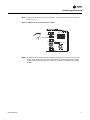
WCIs as Zone Sensor Receivers
On a WCI that functions as a zone sensor receiver, observe the green SNSR LED illuminate to
confirm association with the wireless zone sensor (see Figure 13).
La page charge ...
La page charge ...
La page charge ...
La page charge ...
La page charge ...
La page charge ...
La page charge ...
La page charge ...
La page charge ...
La page charge ...
La page charge ...
La page charge ...
La page charge ...
La page charge ...
La page charge ...
La page charge ...
-
 1
1
-
 2
2
-
 3
3
-
 4
4
-
 5
5
-
 6
6
-
 7
7
-
 8
8
-
 9
9
-
 10
10
-
 11
11
-
 12
12
-
 13
13
-
 14
14
-
 15
15
-
 16
16
-
 17
17
-
 18
18
-
 19
19
-
 20
20
-
 21
21
-
 22
22
-
 23
23
-
 24
24
-
 25
25
-
 26
26
-
 27
27
-
 28
28
-
 29
29
-
 30
30
-
 31
31
-
 32
32
-
 33
33
-
 34
34
-
 35
35
-
 36
36


Trane Wireless Comm Installation, Operation and Maintenance Manual
- Taper
- Installation, Operation and Maintenance Manual
dans d''autres langues
- English: Trane Wireless Comm
Documents connexes
Autres documents
-
 deako DS2005 Manuel utilisateur
-
Lutron Electronics Grafik 5000 Installation Instructions Manual
-
Omega HHF-308 Le manuel du propriétaire
-
Jensen MGH300 Manuel utilisateur
-
Amprobe TMA5 Mini Vane Anemometer Manuel utilisateur
-
Frigidaire PLHV36W7KC Manuel utilisateur
-
-
LG S12AF.UH0 Manuel utilisateur
-
Topcom Twintalker 9100 Le manuel du propriétaire
-
Topcom Butler E400 Mode d'emploi
