Whirlpool AKR 803 IX Program Chart
- Catégorie
- Hottes
- Taper
- Program Chart

5019 318 33244
LI249A-LI248A
INSTALLATIONSANLEITUNGEN
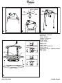
Mindestabstand über der Kochfläche: 50 cm bei Elektroplatten, 70 cm bei Gasmulden oder gemischt
betriebenen Kochfeldern.
Schreiben die Installationsanweisungen des Gaskochfelds einen größeren Abstand vor, ist dieser
natürlich zu beachten.
Schließen Sie das Gerät erst nach seiner kompletten Installation an das Stromnetz an.
Aufgrund des schweren Gewichtes sind mindestens zwei oder noch mehr Personen zur Beförderung
und Installation der Abzugshaube erforderlich.
INSTALLATION SHEET
Minimum distance from burners: 50 cm for electric cookers, 70 cm for gas or combined cookers.
If the installation instructions for the gas cooker specify a greater distance, this must be taken into
account.
Do not connect the appliance to the power supply until installation has been completed.
Very heavy product; hood handling and installation must be carried out by at least two persons.
FICHE D'INSTALLATION
Distance minimale par rapport à la cuisinière : 50 cm minimum dans le cas d'une cuisinière électrique,
70 cm dans le cas d'une cuisinière à gaz ou mixte.
Si les instructions d'installation du dispositif de cuisson à gaz indiquent une distance supérieure, il est
nécessaire de la respecter.
Ne branchez pas l'appareil tant que l'installation n'est pas terminée.
Appareil excessivement lourd ; la manutention et l'installation de la hotte doivent être effectuées par
deux personnes ou plus.
INSTALLATIEKAART
Minimumafstand tot het kooktoestel: 50 cm bij elektrische kooktoestellen, 70 cm bij kooktoestellen
op gas of gemengd.
Als de installatie-instructies van het kooktoestel op gas een grotere afstand aangeven, moet hiermee
rekening gehouden worden.
Geef het apparaat geen stroom totdat de installatie geheel voltooid is.
Aangezien dit apparaat zwaar is, dient het door minstens twee of meer personen verplaatst en
geïnstalleerd te worden.
FICHA DE INSTALACIÓN
Distancia mínima desde los quemadores: 50 cm si las cocinas son eléctricas y 70 cm si son a gas o
mixtas.
Si en las instrucciones de instalación de la placa de cocina a gas se especifica una distancia mayor
respecto a la indicada, es necesario tenerlo en cuenta.
No conecte el aparato a la corriente eléctrica hasta que la instalación esté completamente finalizada.
Producto con peso excesivo; la campana extractora ha de ser transportada e instalada por dos o más
personas.
D
GB
F
NL
E

5019 318 33244
LI249A-LI248A
FICHA DE INSTALAÇÃO
Distância mínima dos fogões: 50 cm no caso de fogões eléctricos, 70 cm no caso de fogões a gás ou
mistos.
Respeite as instruções de instalação do dispositivo de cozedura a gás se estas especificarem uma
distância superior à indicada.
Não ligue o aparelho à corrente eléctrica enquanto a instalação não estiver concluída.
Produto com peso excessivo. A movimentação e a instalação do exaustor devem ser feitas por pelo
menos duas ou mais pessoas.
SCHEDA INSTALLAZIONE
Distanza minima dai fuochi: 50 cm in caso di cucine elettriche, 70 cm in caso di cucine a gas o miste.
Se le istruzioni di installazione del dispositivo di cottura a gas specificano una distanza maggiore
rispetto a quella specificata, bisogna tenerne conto.
Non dare corrente all’apparecchio finché l’installazione non è totalmente completata.
Prodotto dal peso eccessivo, la movimentazione e installazione della cappa deve essere fatta da
almeno due o più persone.
ùüùü+ùùùþ
ü$12.)12.1.)2"0120"FP100!2&102!+012+.FP100!2&1
012+.0! #2 *2* #
ü /0"0.212.1"2"012.".0! #1#12 *0.*20!.)12.1101$1000 #
$0 !12003.!)1202"1$02" /0"
2! 3 / 2020002!)!0*.21#10#!2 !&12"0.212.1"
! ')00 ! "þ02.1.0.212.12 #. !! 32!.!0.02 #$12
.)/* 0!11)20! #".!+ #"
KARTA INSTALACYJNA
Minimalna odległość od palników: 50 cm w przypadku palników elektrycznych, 70 cm w
przypadku palników gazowych lub mieszanych.
Jeżeli w instrukcjach instalacji kuchenki gazowej przewidziana została większa odległość w
stosunku do odległości tutaj wskazanej, należy ją zastosować.
Nie podłączać urządzenia do zasilania, zanim nie zostanie zakończony całkowicie jego montaż.
Urządzenie jest ciężkie. Przenoszenie i instalacja okapu powinny być wykonywane przez co
najmniej dwie osoby.
POPIS INSTALACE
Minimální vzdálenost od sporáků: 50 cm od elektrických sporáků a 70 cm od sporáků na plyn nebo
kombinovaných sporáků.
Jestliže je v pokynech k instalaci plynového spotřebiče určena větší vzdálenost, než je uvedená vzdálenost,
je nutné ji dodržet.
Spotřebič připojte k elektrické síti až po úplném dokončení instalace.
Vzhledem k tomu, že je digestoř velmi těžká, jsou ke stěhování a instalaci spotřebiče nutné minimálně dvě
osoby.
P
I
GR
PL
CZ

5019 318 33244
LI249A-LI248A
INŠTALAČNÁ SCHÉMA
Minimálna vzdialenost od sporáka: 50 cm od elektrických sporákov, 70 cm od plynových a
kombinovaných sporákov.
Ak pokyny na inštaláciu plynovej varnej dosky určujú väčšiu vzdialenost ako je špecifikovaná,
dodržiavajte ich.
Spotrebič nezapájajte do siete, kým nie je inštalácia úplne ukončená.
Výrobok má nadmernú hmotnost, preto je nevyhnutné, aby ho prenášali a inštalovali aspoň dve
alebo viac osôb.
ÜZEMBE HELYEZÉSI ÚTMUTATÓ
A tűzhelytől való minimális távolság: Elektromos tűzhely esetén legalább 50 cm, gáz- vagy
vegyes üzemű tűzhely esetén pedig legalább 70 cm.
Amennyiben a gáztűzhely üzembe helyezési útmutatója nagyobb távolságot ír elő, úgy azt kell
betartani.
A készüléket csak akkor szabad áram alá helyezni, ha a beüzemelés már megtörtént.
Nagy súlya miatt a készülék mozgatását és üzembe helyezését legalább két vagy több
személynek kell végeznie.
СХЕМА УСТАНОВКИ
Минимальное расстояние до конфорок: 50 см в случае электрических плит, 75 см в
случае газовых плит или плит с конфорками обоих типов.
Если инструкциями по установке газового прибора предусмотрено большее
расстояние, то данное указание должно быть соблюдено.
Не подключайте вытяжку к сети электропитания до полного окончания монтажа.
Данный прибор отличается большим весом; для его переноски и установки
требуется не менее двух человек.
КАРТА ЗА ИНСТАЛИРАНЕ
Минимално разстояние от печки: 50 см при електрически печки, 70 см при печки на
газ и комбинирани.
Ако в инструкциите на устройството за готвене на газ е указано по3голямо
разстояние за тази спецификация, трябва да се изпълнява това разстояние.
Не включвайте уреда към мрежата, докато инсталирането не е завършено докрай.
Уред с много голямо тегло 3 преместването и инсталирането на аспиратора трябва
да се извършва от най3малко двама души.
FIȘA DE INSTALARE
Distanţa minimă de la arzătoare: 50 cm faţă de plitele electrice, 70 cm faţă de plitele cu gaz sau
mixte.
Dacă instrucţiunile de instalare ale mașinii de gătit cu gaz specifică o distanţă mai mare decât
cea indicată, trebuie să ţineţi cont de ea.
Nu branșaţi aparatul la curent până când nu terminaţi definitiv operaţia de instalare.
Produs cu greutate mare, deplasarea și instalarea hotei trebuie efectuate de cel puţin două sau
mai multe persoane.
SK
H
RUS
BG
RO

5019 318 33244
LI249A-LI248A
!! "
" " "
#
$
3 x Ø10mm
3 x Ø10mm
max.40 W
(E14)
%
&
%'
(
)
(
(
"(
(
(
(
(@) *++,(
'
-
STOP!
VORDERSEITE - RÜCKSEITE
FRONT
-
BACK
AVANT
-
ARRIÈRE
VOORKANT
-
ACHTERKANT
DELANTE
-
DETRÁS
FRENTE
-
DETRÁS
FRONTE
-
RETRO
üÿ
PRZÓD
-
TYŁ
PŘEDNÍ
-
ZADNÍ
PREDNÁ ČASŤ - ZADNÁ ČASŤ
ELŐLAP
-
HÁTLAP
ПЕРЕДНЯЯ СТОРОНА
3
ЗАДНЯЯ СТОРОНА
ЛИЦЕ
ГРЪБ
FAŢĂ
-
SPATE

5019 318 33244
LI249A-LI248A
FRONTE
RETRO
FRONTE
RETRO
VORDERSEITE - RÜCKSEITE
FRONT
-
BACK
AVANT
-
ARRIÈRE
VOORKANT
-
ACHTERKANT
DELANTE
-
DETRÁS
FRENTE
-
DETRÁS
FRONTE
-
RETRO
üÿ
PRZÓD
-
TYŁ
PŘEDNÍ
-
ZADNÍ
PREDNÁ ČASŤ - ZADNÁ ČASŤ
ELŐLAP
-
HÁTLAP
ПЕРЕДНЯЯ СТОРОНА
3
ЗАДНЯЯ СТОРОНА
ЛИЦЕ
ГРЪБ
FAŢĂ
-
SPATE

5019 318 33244
LI249A-LI248A
-
Vite di sicurezza
Sicherungsschraube
Safety screw
Vis de sécurité
Veiligheidsschroef
Tornillo de seguridad
Parafuso de segurança
Vite di sicurezza
Śruby bezpieczeństwa
Pojistný šroub
Bezpečnostná skrutka
Biztonsági csavar
Блокировочный винт
Предпазни винтове
Șurub de siguranţă

5019 318 33244
LI249A-LI248A
FRONTE
Click!
FRONTE
Click!
FRONTE
FRONTE
VORDERSEITE
FRONT
AVANT
VOORKANT
DELANTE
FRENTE
FRONTE
ü
PRZÓD
PŘEDNÍ
PREDNÁ ČASŤ
ELŐLAP
ПЕРЕДНЯЯ СТОРОНА
ЛИЦЕ
FAŢĂ

5019 318 33244
LI249A-LI248A

5019 318 33244
LI249A-LI248A
D F NL E
GB
P I GR
PL SK H RUS
CZ
BG RO
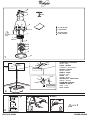
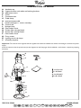
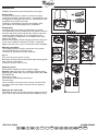
DESCRIPTION OF HOOD
A.
Aesthetic cap
B.
Support bracket with cables and hooking brackets
D.
Adjustment screw
E.
Cover
F.
Connection box
G.
Cable clamp
H.
Interconnection cable
J.
Fitted hood (lights + motor assembly)
K.
Control rod
L.
Halogen lamp
M.
Filter holder frame
N.
Carbon filter (already fitted)
O.
Grease filter (already fitted)
P.
Filter holder frame
Q.
Fixing screws
R.
Lighting unit of side lamps
Y.
Assembly template
Important!
The control rod is supplied with the appliance and must be installed last, before connecting the hood to the power
supply.
Insert the control rod in the special seat (see the diagrams on the first pages of this handbook - with release, compulsory coupling
direction).
max.40 W
(E14)

5019 318 33244
LI249A-LI248A
D F NL E
GB
P I GR
PL SK H RUS
CZ
BG RO
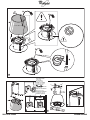
INSTALLATION - ASSEMBLY INSTRUCTIONS
The hood is designed for operation in filter version only:
Air is filtered through a carbon filter and recycled into the
surrounding environment.
The hood is provided with fixing plugs suitable for the majority of walls/ceilings. However, it is necessary to contact a qualified
technician to ascertain suitability of the materials according to the type of wall/ceiling. The wall/ceiling must be strong enough
to take the weight of the hood.
Disconnect the power supply at the main switch in the home during the electrical connection phases.
Fig.2
Place the template (supplied)
Y
(Fig. 2) on the ceiling directly above the cooktop, matching the centre of the template (
R1
)
with the centre of the cooktop (
R2
).
The sides of the template must be parallel to the sides of the cooktop. Prepare the electrical connection.
Note:
The side of the template with the wording “
FRONT
” corresponds to the hood controls side.
Drill the holes indicated on the template, and insert the plugs.
Fig.3
Prepare the support bracket
B
, suitably adjusting the length of the cables according to the following formula:
L (cm)= X-36
L = truss extension
X = distance between the ceiling and the bottom edge of the hood
After finding the right length, secure the cables, tightening the lock nuts (
Fig. 3c
) with a spanner.
Important:
Respect the minimum distance from burners, indicated on the first page of the manual.
Fig.4
Apply the support bracket on the ceiling, passing the cables for the electrical connection through the middle hole.
Fix with 3 screws.
IMPORTANT! Detail B (support bracket) is equipped with a wire (yellow/green) which must be connected to the
earth of the household electrical system.
Fig.5
Fix the lighting unit to the hood with 3 screws and crescent-shaped washers.
Note:
The inside rim of the lighting unit has chamfers which must match the fixing places.
Fig.6
Apply the aesthetic cap
A
to cover the hood, passing the interconnection electrical cable inside.
Important:
Make sure the interconnection cable does not touch the lamps and arrange the excess part using the cable clamps
located at the top of the hood.
Fig.7
Fix the hood to the hooking brackets and secure with 1 screw for each bracket (COMPULSORY FIXING).
Fig.8
Adjust the position of the hood by means of the adjustment screws
D
.
Fig.9
Insert the control rod in the special seat.
Note!
Compulsory coupling direction, with release.
Fig.10
Fix the connection box
F
to the support bracket on the ceiling with 2 screws.
Carry out the electrical connection and secure the cables with the cable clamp
G
with 2 screws.
Fix the connection box cover with 4 screws.
Important!
Replacement of the interconnection cable must be carried out by the authorised after-sales technical service.
Fig.11
Insert the cover
E
between the support cables, making sure they enter the special slots on the cover.
Important!
Leave enough cable so that it passes easily through the slot obtained in the cover.
Secure the cover with 3 grub screws already screwed (or to be screwed) on the support bracket
B
.
Note:
The 3 fixing screws secure the cover by virtue of the friction they exert on the cover itself, and therefore must not be
completely tightened.
Fig.12
Apply the aesthetic tabs I (press-on) to cover the hood fixing rib points

5019 318 33244
LI249A-LI248A
D F NL E
GB
P I GR
PL SK H RUS
CZ
BG RO
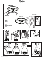
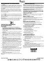
PRODUCT SHEET
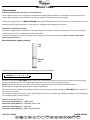
Control panel
Preliminary information for correct use of the hood:
Use the fastest speed in case of particularly concentrated cooking steam and fumes. It is advisable to switch the hood on 5
minutes before starting to cook and leave it running for another 15 minutes at the end of cooking.
The hood is equipped with a “
TOUCH SENSOR
” device able to determine when the control rod is touched by the user, thus
enabling control of lights and speeds. For this purpose, carefully read the following instructions.
Automatic switching on function
The hood is equipped with a temperature sensor that activates the motor at extraction speed (power) 1 when the ambient
temperature in the area surrounding the hood exceeds 70°C.
In any case intervention is possible, to switch off or change the extraction speed (power) (
refer to section “Extraction
speed (power) control”
).
Extraction speed (power) control
Extraction speed (power) selection is cyclic according to the speed sequence
therefore every time the
TOP PART
of the control rod is touched the extraction speed (power) increases by one level and
switches off (stand-by) if the rod is touched again when the hood is on extraction speed (power) 4
Note:
Extraction speed (power) 4 remains on for 5 minutes, after which the extraction motor switches to speed
2
.
By touching the rod again the extraction motor switches off (Stand-by).
The hood can also be switched off (stand-by) when the hood is on any speed, by touching the
TOP PART
of the control rod
for more than 3 seconds.
The hood extraction speed (power) can be determined, since the rod is provided with a LED that changes colour according to
the extraction speed (power) as follows:
Hood on stand-by:
LED OFF
extraction speed (power) 1
- GREEN LED
extraction speed (power) 2
- ORANGE (amber) LED
extraction speed (power) 3
- RED LED
extraction speed (power) 4
- RED LED (FLASHING)
Top
part
Bottom
part
→
stand-by - 1
→
2
→
3
→
4

5019 318 33244
LI249A-LI248A
D F NL E
GB
P I GR
PL SK H RUS
CZ
BG RO
Grease filter cleaning required:
GREEN LED flashing (read the relevant instructions in “Reset and configuration of filter
saturation signalling”)
Carbon filter cleaning or changing required:
ORANGE (amber) LED flashing (read the relevant instructions in “Reset and
configuration of filter saturation signalling”)
Control of middle light
The middle light can be switched on or off by BRIEFLY touching the
BOTTOM PART
of the control rod.
Control of side lights (when provided)
The side lights can be switched on or off by PROLONGED touching of the
BOTTOM PART
of the control rod.
As well as switching on and off, PROLONGED TOUCHING allows adjustment of brightness of the lamps.
Note:
The switching on and off (and adjustment) functions alternate.
Reset and configuration of filter saturation signalling
Switch the hood on at any speed (refer to section “Extraction speed (power) control”)
Reset of grease filter saturation signalling (GREEN LED FLASHING on control rod)
Firstly carry out filter maintenance as described in the relevant section.
To u c h t h e
TOP PART
of the control rod for more than 3 seconds, the LED will stop flashing to indicate that signalling has been
reset, and the hood switches off.
Reset of carbon filter saturation signalling (ORANGE (amber) LED FLASHING)
Firstly carry out filter maintenance as described in the relevant section.
To u c h t h e
TOP PART
of the control rod for more than 3 seconds, the LED will stop flashing, indicating that signalling has been
reset, and the hood switches off.
Deactivation of carbon filter saturation signalling (for particular applications)
Switch off the hood (refer to section “Extraction speed (power) control”)
To u c h t h e
TOP PART
of the control rod for more than 5 seconds, the LED will flash GREEN (amber) indicating deactivation of
carbon filter saturation signalling.
To reactivate carbon filter saturation signalling, repeat the operation, and the LED will flash ORANGE.

5019 318 33244
LI249A-LI248A
D F NL E
GB
P I GR
PL SK H RUS
CZ
BG RO
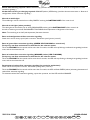
Maintenance
ALWAYS disconnect the hood from the power supply.
Grease filter
It must be cleaned once a month (or when this need is
indicated by the filter saturation system - if provided for) with
non-aggressive detergents, by hand or in a dishwasher at low
temperatures and with short cycle.
Cleaning in a dishwasher may cause discolouring of the
grease filter, but its filtering efficiency is unaffected.
Carbon filter
It absorbs unpleasant odours produced during cooking.
The carbon filter can be washed every two months (or when
the filter saturation system indicates this need) in hot water
and with suitable detergents or in a dishwasher at 65°C
(when cleaning in a dishwasher, do a complete wash cycle
without any dishes).
Remove excess water without damaging the filter, then place
in the oven at 100°C for 10 minutes to dry it completely.
Replace the mat every 3 years or when the cloth is damaged.
Removing the filters
The metal grease filter and the carbon filter are installed
coupled at the bottom (extraction area).
To remove or refit them, proceed as follows:
Fig.11
a+c
. turn the three screws 1/4 turn.
b+d+e
. remove the filter holder frame and the metal grease
filter (and the carbon filter).
Proceed in reverse order to refit.
Replacing lamps
Disconnect the appliance from the power supply.
Caution!
Make sure lamps are cold before touching them.
Replacing the middle lamp: only use halogen lamps max. 40W
40° D25 GU10.
Removing the lamp:
twist 1/4 turn anticlockwise and remove.
To fit the lamp:
insert the lamp in the special seat so that its contacts enter
the seats on the lamp holder, and twist 1/4 turn (approx.)
clockwise.
Replacing the side lamps
Pull off the aesthetic cap upwards and unscrew the burnt-out
lamp; replace only with olive-shaped lamps 40Wmax. (E14)
Fig.11

5019 318 33244
LI249A-LI248A
D F NL E
GB
P I GR
PL SK H RUS
CZ
BG RO
SAFEGUARDING THE ENVIRONMENT
1. Packing
The packing materials are 100% recyclable and are marked with the
recycling symbol . Comply with local regulations for disposal. The
packing materials (plastic bags, polystyrene parts, etc.) are a potential
source of danger and must be kept out of the reach of children.
2. Product
This appliance is marked in compliance with European Directive
2002/96/EC on Waste Electrical and Electronic Equipment (WEEE).
By ensuring that this appliance is correctly scrapped, the user can
help prevent potentially harmful consequences for the environment
and the health of people.
The symbol on the product or the accompanying documentation
indicates that it should not be treated as domestic waste but must be
taken to a suitable collection centre for the recycling of electrical and
electronic equipment.
Disposal must be carried out in compliance with local regulations on
waste disposal.
For further information on the treatment, recovery and recycling of this
product, contact the competent local office, the household waste
collection service or the shop where you purchased the appliance.
PRECAUTIONS AND GENERAL
RECOMMENDATIONS
IMPORTANT!
• The appliance is not intended for use by children or
people with limited physical, sensory or mental abilities or
without experience and knowledge of it, unless they are
supervised or instructed in its use by a person responsible
for their safety.
• Children must be supervised so that they do not play with
the appliance.
1. Do not connect the appliance to the mains power supply until
installation has been completed. Always disconnect the hood before
any cleaning or maintenance, by unplugging it or turning off the main
switch in the home.
2. Do not “flambé” food under the hood. Naked flames could cause a
fire.
3. Do not leave pans unattended when frying, since the cooking oil
could catch fire.
4. Regular cleaning and maintenance is essential for correct hood
operation and good performance. Regularly clean all deposits from
dirty surfaces. Regularly remove and clean or change the filter. Do
not use flammable materials to duct the extracted air.
5. If the hood is used together with other appliances operating on gas
or other fuels, the negative pressure in the room must not exceed
4Pa (4 x 10⁻⁵ bar). Therefore, make sure the room is adequately
ventilated.
6. The air extracted by the hood must not be removed through the
flue of the heating system or other appliances that use gas or other
fuels.
7. The room must be adequately ventilated when the hood is used
together with appliances operating on gas or other fuels.
8. Make sure lamps are cold before touching them.
9. The discharge air must not be ducted in a flue used for removing
fumes produced by appliances operating on gas or other fuels,
but must have a separate outlet.
All national regulations on air discharge must be observed.
10. The hood is not a shelf, therefore do not overload or place
objects on it.
11.
Do not use or leave the hood without its lamps correctly
installed - risk of electric shock
.
Note:
Always wear work gloves for all installation and maintenance
operations.
Electrical connection
The mains power supply must match the voltage given on the
dataplate located inside the hood. If provided with a plug, connect
the hood to a socket complying with current regulations and located
in an accessible area. If it does not have a plug (direct connection to
the power supply) or if the socket is not in an accessible place, fit a
suitable double-pole switch that ensures complete disconnection
from the power supply in category III overvoltage conditions,
complying with the installation rules.
IMPORTANT: Before reconnecting the hood circuit to the
power supply and checking correct operation, always make
sure the power cable is correctly fitted and that it was NOT
crushed in its housing during installation.
Cleaning the hood
Warning!
Failure to remove oil/grease (at least once a month) could
result in fire.
Use a soft cloth with a neutral detergent. Never use abrasive
substances or alcohol.
Before using the hood
To ensure best use of your hood, please read these instructions
carefully and keep them for future reference.
The packing materials (plastic bags, polystyrene parts, etc.) are a
potential source of danger and must be kept out of the reach of
children.
Make sure the hood was not damaged during transport.
Declaration of conformity
This product has been designed, manufactured and put on the
market in conformity with the following:
- safety objectives of "Low Voltage" Directive 73/23/EEC
- protection requirements of “EMC” Directive 89/336/EEC
amended by Directive 93/68/EEC.
Troubleshooting guide
The hood does not work:
• Is the plug properly inserted in the power socket?
• Is there a power failure?
The hood is not extracting enough:
• Is the right speed selected?
• Do the filters need cleaning or changing?
• Are the air outlets blocked?
The light does not work:
• Does the lamp need replacing?
• Is the lamp correctly fitted?
AFTER-SALES SERVICE
Before calling the After-Sales Service
1. See if you can eliminate the problem on your own (refer to
”Troubleshooting guide”).
2. Switch the hood off and then on again to check if the problem
has been eliminated.
3. If the problem persists, contact the After-Sales Service.
Specify:
•the type of fault,
• the product model given on the dataplate inside the hood, visible
on removing the grease filters.
• your full address,
• your telephone number and area code.
• the Service code (the number under the word SERVICE on the
dataplate inside the hood, behind the grease filter).
If any repairs are necessary, contact an authorised Service Centre (to
ensure the use of original spare parts and correct repair).
Failure to comply with these instructions can compromise the safety
and quality of the product.
-
 1
1
-
 2
2
-
 3
3
-
 4
4
-
 5
5
-
 6
6
-
 7
7
-
 8
8
-
 9
9
-
 10
10
-
 11
11
-
 12
12
-
 13
13
-
 14
14


Whirlpool AKR 803 IX Program Chart
- Catégorie
- Hottes
- Taper
- Program Chart
dans d''autres langues
- English: Whirlpool AKR 803 IX
Documents connexes
-
Whirlpool AKR 823/WH Program Chart
-
-
IKEA HO EV W Mode d'emploi
-
Whirlpool AKR 431 WH Program Chart
-
-
Whirlpool AKR 952 IX WP Le manuel du propriétaire
-
-
-