
User’s Guide
MIL-FT240TX
10/100 Fault-Tolerant Stand-Alone
Transceiver
• 10/100 Base-T(x) to 10/100 Base-T(x)
• Ethernet/Fast Ethernet
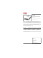
The MIL-FT240TX is a fault-tolerant
transceiver, providing redundant paths for fast Ethernet devices. It has three ports: main,
primary, and backup. Typically, the main port connects to a critical 10/100 fast Ethernet
device. The primary port and the backup port connect to two different switch ports or two
different ports on separate switches. When the unit powers up, it checks the primary port
for a link signal; if the signal is present, the main and primary ports will connect and the
signal from the backup port is disabled. Any device connected to the backup port will not
detect a signal at this time. However, if the device does not detect a signal on the primary
port, then the main port and backup port connect.
Product features . . . . . . . . . . . . . . . .2
Installation . . . . . . . . . . . . . . . . . . . .3
Operation . . . . . . . . . . . . . . . . . . . . .5
Cable Specifications . . . . . . . . . . . . .6
Troubleshooting . . . . . . . . . . . . . . . .7
Technical Specifications . . . . . . . . . .9
Contact Us . . . . . . . . . . . . . . . . . . .10
Compliance Information . . . . . . . . .11
*Typical maximum cable distance. Actual distance is dependent upon the physical
characteristics of th network.
Part Number Port One - Copper
10/100Base-T(x)
Port Two Copper
10/100Base-T(x)
Port Three - Copper
10/100Base-T(x)
MIL-FT240TX RJ-45 100 M
(328 ft*)
RJ-45 100 M
(328 ft*)
RJ-45 100 M
(328 ft*)

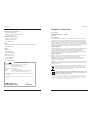
Product Features
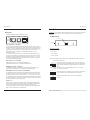
Front panel
The MIL-FT240TX has three 10/100Base-T(x) ports.
Auto-Negotiation (selectable)
The Auto-Negotiation feature automatically configures the transceiver to achieve
the best possible mode of operation over a link. The transceiver broadcasts its speed
(10 Mb/s or 100 Mb/s) and duplex capabilities (full or half) to the other devices and
negotiates the best mode of operation. Auto-Negotiation allows quick and easy
installation because the optimal link is established automatically—no user
intervention required.
In a scenario where the media converter is linked to a non-negotiating device, the
user may want to disable Auto-Negotiation. In this instance, the mode of operation
will drop to the least common denominator between the two devices (e.g., 10 Mbs,
half-duplex). Disabling this feature gives the user the ability to force the connection
to the desired speed and duplex mode.
Data Transfer rate (selectable)
10Base-T data transfer rate: 10 Mbps baseband Ethernet
100Base-TX data transfer rate: 100 Mbps baseband Ethernet
Full-Duplex network (selectable)
In a full-duplex network, maximum cable lengths are determined by the type of
cables used. The 512-Bit Rule does not apply in a full-duplex network.
Half-Duplex network (selectable) (512-Bit Rule)
In a half-duplex network, the maximum cable lengths are determined by the round
trip delay limitations of each fast Ethernet collision domain. (A collision domain is
the longest path between any two terminal devices, e.g., terminal, switch, or router.)
The 512-Bit Rule determines the maximum length of cable permitted by calculating
the round-trip delay in bit times (BT) of a particular collision domain. If the result is
less than or equal to 512 BT, the path is good.
AutoCross™
When the AutoCross feature is activated, it allows either straight-through MDI or
crossover MDI-X cables to be used when connecting to 10Base-T or 100Base-TX
devices. AutoCross determines the characteristics of the connection and
automatically configures the unit to link up, regardless if the cable configuration is
MDI or MDI-X. This feature is ON permanently.
2
PWR
Primary
Backup
Main Primary Backup
10/100Base-TX 10/100Base-TX 10/100Base-TX
MIL-FT240TX
Technical Support: 1.800.466.4526. Press "2" -- International: 1.408.744.2751
Installation
CAUTION: Do Not install the MIL-FT240TX transceiver in location where it might be
exposed to wetness. Failure to observe this caution could result in damage to the
transceiver.
Set DIP Switch
Four (4) Dip Switches
• SW 1: Auto-Negotiation
• SW 2: Speed
• SW 3: Duplex
• SW 4: Not Used
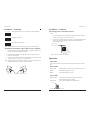
Note: See the diagrams below and use a very small flatblade screwdriver or similar
device to set the DIP switch.
When Auto-Negotiation is enabled (switch #1 UP), the transceiver
advertises all rate and mode capabilities to the network: 100Mb/s full
duplex, 100Mb/s half-duplex, 10Mb/s full duplex, and 10Mb/s half
duplex.
Note: Switches “#3” and “#4” are non-functional when switch “#1” is in the UP
position (Auto-Negotiation enabled).
When auto-negotiation is disabled (switch #1 DOWN), the transceiver
does not advertise rate and mode capabilities to the network.
100Base-TX data transfer rate (switch #2 UP): 100 Mbps fast
Ethernet.
1342
Up
1342
Down
1342
Up
3
MIL-FT240TX
Email: [email protected]
Side V i ew
RJ-45 P orts
4 DIP Switches

4
MIL-FT240TX
Technical Support: 1.800.466.4526. Press "2" -- International: 1.408.744.2751
Installation -- Continued
10Base-TX data transfer rate (switch #2 DOWN): 10 Mbps Ethernet.
Full duplex switch #3 UP.
Half duplex switch #3 DOWN.
Note: The functionality for each switch setting applies to all ports simultaneously.
1342
Down
1342
Up
1342
Down
Installing the twisted-pair copper cable (customer supplied)
1. Locate or build an IEEE 803.2 compliant 10Base-T or 100Base-TX cables, with
male RJ-45 connectors installed onto both ends.
2. Connect the RJ-45 connector at one end of the cable to the RJ-45 port on the
transceiver as shown below.
3. Connect the RJ-45 connector at the other end of the cable to the RJ-45 port on the
other device (switch, workstation, etc.) as shown below.
Note: The MDI (straight-through) cable or the MDI-X (crossover) cable connection is
configured automatically, according to network conditions.
RJ-45 Port
Transceiver
RJ-45 Port
Switch,Workstation, etc.
5
MIL-FT240TX
Installation -- continued
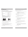
Connecting power to the media converter
AC/DC:
1. Connect the barrel connector of the adapter to the power port of the transceiver
(located on the back of the transceiver shown below).
2. Connect the power adapter plug into AC power: if all the configuration switches
are in the UP position, the port LEDs will flicker during the initialization
process and then go OFF.
Note: The power-on LED will be lit (ON).
Operation
Status LEDs
There are three (3) LEDs on the converter chassis front panel and two (2) on each TP
port.
Chassis LEDs
Power (PWR): LED ON indicates connection to an external AC power source
Primary: ON when the primary port is in use
Backup: ON when the backup port is in use
TP port LEDs
LINK/ACT/SPD: Green (ON) for 100 Mbps and Link/Act; Flashing when
transmitting data; Orange for 10Mbps
Duplex (DPX): Green (ON) for full duplex; OFF for half duplex
Chassis Rear
Barrel-Connector
Power Receptacle
TP Por t
Dupl ex (DPX)
Li nx/Act/SPD
Email: [email protected]

Cable Specifications
Copper cable (10Base-T/100Base-TX)
Ensure that the correct cable type is installed to support the highest speed and mode of
operation. Though category 3 cable is adequate for a 10Base-T installation, category 5
cable is recommended, since category 3 cable DOES NOT support 100Base-TX.
Category 3: (minimum requirement for 10 Mb/s operation)
Gauge: 24 to 22 AWG
Attenuation: 11.5 dB/100m @ 5-10 MHz
Maximum cable distance: 100 meters
Category 5: (minimum requirement for 100 Mb/s operation)
Gauge: 24 to 22 AWG
Attenuation: 22.0 dB /100m @ 100 MHz
Maximum cable distance: 100 meters
• Straight-through (MDI) or crossover (MDI-X) cable may be used.
• Shielded (STP) or unshielded (UTP) twisted-pair cable may be used.
• Pins 1/2 and 3/6 are the two active pairs in an Ethernet network.
• Use only dedicated wire pairs for the active pins:
(e.g., blue/white & white/blue, orange/white & white/orange, etc.)
• Do not use flat or silver satin wire.
10Base-T and the Ethernet collision domain:
• Refer to the 5-Segment Rule before installing half-duplex 10Base-T
cable.
• Installing full-duplex twisted-pair cable avoids collision domain
considerations—maximum distance 100 meters.
100Base-TX and the Fast Ethernet collision domain:
•
Refer to the 512-Bit Rule before installing half-duplex 100Base-TX cable.
• Installing full-duplex twisted-pair cable avoids collision domain
considerations—maximum distance 100 meters.
Note: A Fast Ethernet collision domain can have only “1” Class “I” repeater or “2”
Class “II” repeaters.
6
MIL-FT240TX
Technical Support: 1.800.466.4526. Press "2" -- International: 1.408.744.2751
Crossover Cable
1
2
3
6
Straight-Through Cable
Twisted Pair #1
Twisted Pair #1
Twisted Pair #2
Twisted Pair #2
1
2
3
6
1
2
3
6
1
2
3
6
Troubleshooting
If the MIL-FT240TX fails or initially does not power up and function properly, ask the
following questions and take the suggested corrective actions.
1. Is the power LED on the transceiver ON?
NO:
a. Is the barrel connector from the external power supply fully inserted into
the transceiver?
b. Is the adapter plugged into an external power source?
c. Contact Technical Support: 1.800.466.4526, then press "2."
YES: Go to step 2.
2. Is there an active (connected to an output source) RJ-45 cable inserted into the
transceiver main port?
NO:
a. Insert an RJ-45 cable into the transceiver main port
b. Insert the other cable end into an active device
YES: Go to step 3.
3. Is the link/active LED on the main port lit (ON)?
NO:
a. Check that the RJ-45 cable is properly inserted into the transceiver main
port.
b. Check that the other cable end is inserted into an active device
c. Check the cable for damage
d. Contact Technical Support
YES: Go to step 4.
4. Is there an RJ-45 cable inserted into the primary port on the transceiver?
NO:
a. Insert the RJ-45 cable into the transceiver primary port
b. Insert the other end of the cable into the input of an active device
YES: Go to step 5.
5. Is the primary LED on the chassis lit (ON)?
NO:
a. Check that the RJ-45 cable is properly inserted into the primary port
b. Check that the other end of the cable is properly inserted into an active
device
c. Check the cable for damage
d. Contact Technical Support
YES: Go to step 6.
7
MIL-FT240TX
Email: [email protected]

9
MIL-FT240TX
Email: [email protected]
Technical specifications
Standards: IEEE 802.3™ 2000
Regulatory: Emissions: EN55022 Class A, Immunity:
EN55024
Safety compliance: UL listed, CE Mark (wall-mount power supply)
Data Rate: 10 Mbps, 100 Mbps
Dimensions: 3.25” W, 1” H, 4.8” L (82.6 mm x 25 mm x
121.9mm)
Weight: 10 oz. approximate
Power consumption: 2.4 watts
Power supply: 12VDC, 0.4A minimum
Operating temp: 0°C to 50°C (32°F to 140°F )
Switching time: <189 ms (primary to secondary)
Storage temp: -20°C to +85°C (-4°F to 185°F)
Humidity: 5% to 95%, non-condensing
Altitude: 0 – 10,000 feet
Warranty: 5 year limited
Troubleshooting -- continued
6. Is there an RJ-45 cable inserted into the backup port on the transceiver?
NO:
a. Insert the RJ-45 cable into the transceiver backup port
b. Insert the other end of the cable into the input of the an active device
YES: Go to step 7.
7. Is the backup LED on the chassis lit (ON)?
NO:
a. Check that the RJ-45 cable is properly inserted into the backup port.
b. Check that the other end of the cable is properly inserted into an active
device
c. Check the cable for damage
c. Contact technical support
YES: If the LED is ON and still no activity, contact technical support:
1.800.466.4526, then press "2."
MIL-FT240TX
Technical Support: 1.800.466.4526. Press "2" -- International: 1.408.744.2751
8

Contact Us
North American technical support
E-mail: [email protected]
Telephone: +1.800.466.4526. then Press "2"
Fax: +1.408.744.2793
International technical support
E-mail: [email protected]
Telephone: +1.408.744.2751
Fax: +1.408.744.2793
E-Mail
Ask a question anytime by sending an e-mail to our technical support staff.
Address
Headquarters:
MiLAN Technology
1329 Moffett Park Drive
Sunnyvale, CA 94089
Phone: 408-744-2775
Toll Free: 800-466-4526
Fax: 408-744-2871
Email: [email protected]
10
MIL-FT240TX
Technical Support: 1.800.466.4526. Press "2" -- International: 1.408.744.2751
Declaration of Conformity
Name of Mfg: Transition Networks, 6475 City West Parkway,
Minneapolis, MN 55344 U.S.A.
Model: MIL-FT240TX Stand-Alone Transceiver
Part Number: MIL-FT240TX
Regulation: EMC Directive 89/336/EEC
Purpose: To declare that the MIL-FT240TX to which this declaration
refers is in conformity with the following standards:
CISPR 22:1997+A1:2000; EN 55022:1998+A1:2000 Class A; FCC Part 15 Subpart B;
21CFR subpart J
I, the undersigned, hereby declare that the equipment specified above conforms to the above Directive(s)
and Standard(s).
October 5, 2005
Stephen Anderson, Vice-President of Engineering Date
11
MIL-FT240TX
Email: [email protected]
Compliance Information
CSA Certified
CISPR22/EN55022 Class A + EN55024
CE Mark
FCC regulations
This equipment has been tested and found to comply with the limits for a class A digital device,
pursuant to part 15 of the FCC rules. These limits are designed to provide reasonable protection
against harmful interference when the equipment is operated in a commercial environment. This
equipment generates, uses, and can radiate radio frequency energy and, if not installed and used in
accordance with the instruction manual, may cause harmful interference to radio communications.
Operation of this equipment in a residential area is likely to cause harmful interference, in which
case the user will be required to correct the interference at the user’s own expense.
Canadian Regulations
This digital apparatus does not exceed the Class A limits for radio noise for digital apparatus set out
on the radio interference regulations of the Canadian Department of Communications.
Le présent appareil numérique n'émet pas de bruits radioélectriques dépassant les limites
applicables aux appareils numériques de la class A prescrites dans le Règlement sur le brouillage
radioélectrique édicté par le ministère des Communications du Canada.
European Regulations
WARNING: This is a Class A product. In a domestic environment this product may cause radio
interference in which case the user may be required to take adequate measures.
Achtung ! Dieses ist ein Gerät der Funkstörgrenzwertklasse A. In Wohnbereichen können bei
Betrieb dieses Gerätes Rundfunkstörungen auftreten. In diesem Fäll ist der Benutzer für
Gegenmaßnahmen verantwortlich.
Attention ! Ceci est un produit de Classe A. Dans un environment domestique, ce produit risque de
créer des interférences radioélectriques, il appartiendra alors à l'utilsateur de prende les measures
spécifiques appropriées.
In accordance with European Union Directive 2002/96/EC of the European Parliament
and of the Council of 27 January 2003, Transition Networks will accept post usage
returns of this product for proper disposal. The contact information for this activity can be
found in the 'Contact Us' portion of this document.
CAUTION: RJ connectors are NOT INTENDED FOR CONNECTION TO THE
PUBLIC TELEPHONE NETWORK. Failure to observe this caution could result
in damage to the public telephone network.
Der Anschluss dieses Gerätes an ein öffentlickes Telekommunikationsnetz in den EG-Mitgliedstaaten
verstösst gegen die jeweligen einzelstaatlichen Gesetze zur Anwendung der Richtlinie 91/263/EWG zur
Angleichung der Rechtsvorschriften der Mitgliedstaaten über Telekommunikationsendeinrichtungen
einschliesslich der gegenseitigen Anerkennung ihrer Konformität.

12
MIL-FT240TX
Trademark notice
All registered trademarks and trademarks are the property of their respective owners.
Copyright restrictions
© 2004-2005 Transition Networks. All rights reserved. No part of this work may be reproduced or
used in any form or by any means—graphic, electronic or mechanical—without written permission
from Transition Networks
Printed in the U.S.A. 33344.A
-
 1
1
-
 2
2
-
 3
3
-
 4
4
-
 5
5
-
 6
6
-
 7
7


dans d''autres langues
- English: MiLAN MIL-FT240TX User manual
Autres documents
-
SMC Networks 8150L2 Manuel utilisateur
-
-
-
LG-Ericsson ipecs ES-5048XG Guide d'installation
-
Brocade Communications Systems 53-1002580-01 Manuel utilisateur
-
Transition Networks J/FE-CF-04 SMLC Manuel utilisateur
-
red lion EL228 Guide d'installation
-
Transition Networks CBFTF1010-130 Manuel utilisateur
-
-