
B347533396COM04GO
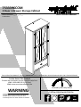
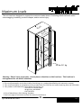
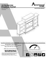
- Unit can tip over causing severe injury or death.
- Anchor unit to stud in wall (if instructed to).
- Do Not allow children to climb on unit.
- Put heavy items on lower shelves or drawers.
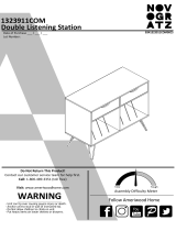
WARNING
THIS INSTRUCTION BOOKLET CONTAINS IMPORTANT SAFETY INFORMATION. PLEASE READ AND KEEP FOR FUTURE REFERENCE.
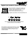
Do Not Return This Product!
Contact our customer service team for help first.
Call: 1-800-489-3351 (toll free)
Visit: www.ameriwoodhome.com
Follow Ameriwood Home
Date of Purchase ___ / ___ / ___
Lot Number:
7533396COM
2 Door 1 Drawer Storage Cabinet
Tube
You
Assembly Difficulty Meter
Easy Tough

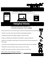
Do NOT return this product!
Contact our friendly customer service team first for help.
Call us!
1-800-489-3351
Visit ameriwoodhome.com
Assembly Tips
- Open your item in the area you plan to keep it to avoid excessive heavy lifting.
- Identify, sort and count the parts before attempting assembly.
- Compression dowels are lightly tapped in with a hammer.
- Slides are labeled with a R (right) and L (left) for proper placement.
- Make sure to always face the point on the top of the Cam Lock towards the
outer edge.
- Use all the nails provided for the back panel and spread them out equally.
- Back panel must be used to make sure your unit is sturdy.
- Do NOT use harsh chemicals or abrasive cleaners on this item.
- Never push, pull, or drag your furniture.
Tube
You
PEOPLE NEEDED FOR ASSEMBLY: 2
ESTIMATED ASSEMBLY TIME: 1 HOUR
Helpful Hints
2
Tube
You
systembuild.com

P
Quick
Tip
Assembly
P
P
P
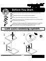
Read through each step carefully and follow the proper order
Separate and count all your parts and hardware
Give yourself enough room for the assembly process
Have the following tools: Flat Head Screwdriver, #2 Phillips Head
Screwdriver and Hammer
Caution: If using a power drill or power screwdriver for screwing,
please be aware to slow down and stop when screw is tight.
Failure to do so may result in stripping the screw.
P
Before You Start
Cam Lock Fastening System
This Cam Lock Fastening System will be used throughout the assembly process.
1
3
2
4
3
Tube
You
systembuild.com

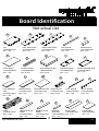
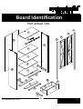
Board Identification
Not actual size
TOP
T7533396010GO
QTY: 1 PC
A
4
Tube
You
LEFT SIDE PANEL
T7533396020GO
QTY: 1 PC
B
RIGHT SIDE PANEL
T7533396030GO
QTY: 1 PC
C
TOP APRON
T7533396040GO
QTY: 1 PC
D
WOOD BLOCK
T7533396050GO
QTY: 1 PC
E
FIXED SHELF
T7533396060GO
QTY: 1 PC
F
LOWER APRON
T7533396070GO
QTY: 2 PCS
G
ADJUSTABLE SHELF
T7533396080GO
QTY: 2 PCS
H
DRAWER FRONT
T7533396091GO
QTY: 1 PC
I
RIGHT DRAWER SIDE
T7533396102GO
QTY: 1 PC
J
LEFT DRAWER
SIDE
T7533396112GO
QTY: 1 PC
K
DRAWER BACK
T7533396121GO
QTY: 1 PC
L
DRAWER BOTTOM
T7533396131GO
QTY: 1 PC
M
WOOD BLOCK
T7533396141GO
QTY: 2 PCS
N
RIGHT APRON
T7533396160GO
QTY: 1 PC
O
DOOR
T7533396170GO
QTY: 2 PCS
Q
FRONT BOTTOM
PANEL
T7533396180GO
QTY: 1 PC
R
REAR BOTTOM
PANEL
T7533396190GO
QTY: 1 PC
S
DRAWER
SUPPORT
T7533396200GO
QTY: 1 PC
T
FIXED SHELF
T7533396220GO
QTY: 1 PC
V
systembuild.com
LEFT APRON
T7533396150GO
QTY: 1 PC
P
BACK PANEL
T7533396210GO
QTY: 1 PC
U

Board Identification
Not actual size
5
Tube
You
systembuild.com
A
B
C
D
E
F
G
G
H
H
I
J
K
L
M
N
N
O
P
Q
Q
R
S
T
U
V

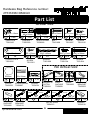
Part List
Hardware Bag Reference number:
27533396COM2GO
Actual Size
×30 ×29
WOOD DOWEL
TGO2900
Ø8 x 30mm
Ø15 x 10mm
CAM LOCK
TGO2100
1 ×30
CAM BOLT
TGO2000
M8 x 20mm
6
Tube
You
×10
SCREW
TGO1001
Ø4.2 x 25mm
23
15
systembuild.com
×30
SCREW
TGO1301
Ø3 x 12mm
8
×6
M4 x 19mm
×5
Ø4.2 x 45mm
SCREW
TGO1008
BOLT
TGO1608
×4
Ø3 x 15mm
SCREW
TGO1315
×22
SCREW
TGO1007
Ø3.5 x 12mm
4 5 6
×4
45 x 12 x 1mm
STRIKE PLATE
TGO3525
79 x29
Ø4.2 x 13mm
SCREW
TGO1304
11 ×1
SCREW
TGO1314
Ø4.2 x 28mm
12
×10
COVER
TGO2232
Ø20mm
13 ×4
WOOD DOWEL
TGO2907
14
Ø8 x 20mm
No Actual Size
×1 set
14"
left cabinet
member
left drawer
member
×1 set
right cabinet
member
right drawer
member
METAL SLIDE
TGO4513
23
22
22-1 22-2 23-1 23-2 14"
×3
HANDLE
TGO5510
24
×2
DRAWER
BRACKET
TGO6513
21
×8
SHELF
SUPPORT
TGO2800
20
x2
MAGNETIC
CATCH
TGO6511
16 x1
Ø6 x 30mm
WALL
ANCHOR
TGO6501
17 x6
HINGE
TGO4306
18 x1
30x50x20mm
WALL
BRACKET
TGO3502
19

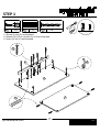
STEP 1
1.1 Screw (2) into (A) as illustrated.
1.2 Attach (D) & (E) to (A) with (3) & (9) as illustrated.
1.3 Insert (3) into (V) as illustrated.
×4
7
Tube
You
2
V
systembuild.com
×7
3 ×5
9
3
2
9
A
E
D

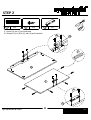
STEP 2
8
Tube
You
×6
3 6
2.1 Insert (3) into (F) as illustrated.
2.2 Attach (16) to (E) & (F) with (6) as illustrated.
systembuild.com
×4 16 ×2
3
16
6
16
6
F
A
E

STEP 3
9
Tube
You
×8
2 11
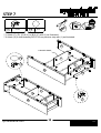
3.1 Screw (2) into (O) & (P) as illustrated.
3.2 Attach (18) to (O) & (P) with (11) as illustrated.
systembuild.com
×12 18 ×6
2
11
18
O
P

4.1 Screw (2) into (B), (C) & (G) as illustrated.
4.2 Insert (3) into (B), (C), (R) & (S) as illustrated.
STEP 4
10
Tube
You
systembuild.com
×16
2 ×16
3
S
R
G x 2
B
C
3
2

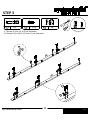
5.1 Attach (O) to (B) with (1) as illustrated.
5.2 Attach (P) to (C) with (1) as illustrated.
5.3 Attach (G) to (F) & (R) with (1) as illustrated.
STEP 5
11
Tube
You
Proper orientation of CAM LOCK
Tip
Quick
Assembly
UNLOCK
LOCK
×12
113
systembuild.com
×6
R
G
G
F
B
O
P
C
1
13

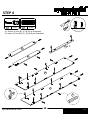
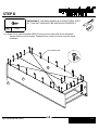
6.1 Attach (N) to (B) & (C) with (14) & (15) as illustrated.
6.2 Attach (22-2) & (23-2) to (N) with (5) as illustrated.
STEP 6
12
Tube
You
×85
systembuild.com
×4
14 ×415 ×1
22-2 ×1
23-2
555
22-2
23-2
15
N
14
15
14
N
C
B
5
5
5

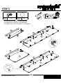
STEP 7
13
Tube
You
7.1 Attach (F), (R), (S) & (V) to (B) & (C) with (1) as illustrated.
7.2 Attach (A) to sub-assembly B/C/F/V from previous step with (1) as illustrated.
Proper orientation of CAM LOCK
Tip
Quick
Assembly
UNLOCK
LOCK
systembuild.com
×16
113 ×4
FINISHED EDGE
C
B
V
F
R
S
V
F
B
C
A
1
1
13

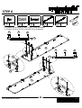
STEP 8
14
Tube
You
8.1 Attach (U) to sub-assembly A/B/C/F from previous step with (8) as illustrated.
* Assure that the unit is square. Distance from corner to corner must be equal
as shown.
systembuild.com
×308
IMPORTANT! THE BACK PANEL IS A STRUCTURAL PART
OF THIS UNIT AND MUST BE INSTALLED PROPERLY.
8
A
C
U
B
Raw material side

STEP 9
15
Tube
You
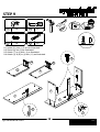
9.1 Insert (21) into (J) & (K) as illustrated.
9.2 Screw (2) into (I) as illustrated.
9.3 Attach (T) to (I) with (1) as illustrated.
9.4 Attach (J) & (K) to (I) with (11) as illustrated.
Proper orientation of CAM LOCK
Tip
Quick
Assembly
UNLOCK
LOCK
systembuild.com
×2
12 ×2
×4
11 21 ×2
2
I
JK
21 21
1
11
I
J
K
T

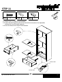
STEP 10
16
Tube
You
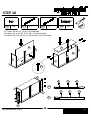
10.1 Insert (M) into (J), (K) & (I) as illustrated.
10.2 Attach (L) to (J), (K) & (T) with (15) as illustrated.
10.3 Attach (22-1) & (23-1) to (J) & (K) with (5) as illustrated.
systembuild.com
×65 22-1 ×1 23-1 ×1 15 ×6
K
J
M
15
K
J
M
T
L
K
J
23-1
22-1
22-1
23-1
555
5 55

STEP 11
17
Tube
You
11.1 Attach (24) to (I) with (4) as illustrated.
11.2 Insert the shelf supports (20) at the desired level and place the adjustable
shelves (H) onto the shelf supports.
11.3 Push the drawer into cabinet as illustrated.
systembuild.com
×2
420 ×8 24 ×1
Cabinet Slide
Drawer Slide
20
H
H
I
I
24
4

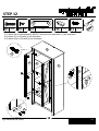
STEP 12
18
Tube
You
12.1 Attach (Q) to sub-assembly A/B/C/F from previous step with (11) as illustrated.
12.2 Attach (7) to (Q) with (5) as illustrated.
12.3 Attach (24) to (Q) with (4) as illustrated.
systembuild.com
×4
4 ×85 ×4
724 ×2 ×12
11
4
424
A
BC
Q
Q
F
7
5
11
Q

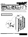
STEP 13
19
Tube
You
systembuild.com
×1
12 17 ×1 ×1
11 19 ×1
12
19
17 11
Wall
Hole
13.1 Drill a 3/16" (5mm) diameter hole in the wall. Tap the wall anchor (17) into the hole until it is flush.
13.2 Fasten wall bracket (19) to wall anchor (17) with screw (12). Make sure screw (11) is fully tightened.
For Masonry, Concrete, or other wall materials:
Consult your local hardware store for appropriate
anchors to securely attach the safety bracket
IMPORTANT: THIS UNIT MUST BE SECURE TO THE WALL TO HELP PREVENT TIPOVER. FOLLOW THESE
INSTRUCTIONS TO INSTALL THE ANTI-TIPPING SAFETY BRACKET PROVIDED WITH THIS PRODUCT.

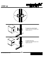
STEP 14
20
Tube
You
systembuild.com
B
A
Door
Door
Cabinet
Cabinet
To adjust the vertical heght.
Loosen screw "A" and adjust door.
Tighten screw "A".
To adjust side ways.
Loosen screw "B" and adjust door.
Tighten screw "B".
La page est en cours de chargement...
La page est en cours de chargement...
La page est en cours de chargement...
La page est en cours de chargement...
La page est en cours de chargement...
La page est en cours de chargement...
La page est en cours de chargement...
La page est en cours de chargement...
La page est en cours de chargement...
La page est en cours de chargement...
-
 1
1
-
 2
2
-
 3
3
-
 4
4
-
 5
5
-
 6
6
-
 7
7
-
 8
8
-
 9
9
-
 10
10
-
 11
11
-
 12
12
-
 13
13
-
 14
14
-
 15
15
-
 16
16
-
 17
17
-
 18
18
-
 19
19
-
 20
20
-
 21
21
-
 22
22
-
 23
23
-
 24
24
-
 25
25
-
 26
26
-
 27
27
-
 28
28
-
 29
29
-
 30
30


SYSTEMBUILD EVOLUTION 7533396COM Manuel utilisateur
- Taper
- Manuel utilisateur
- Ce manuel convient également à
dans d''autres langues
Autres documents
-
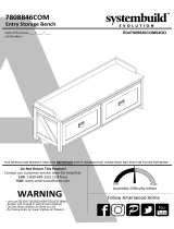 Dorel Home 7808846COM Assembly Manual
-
 Dorel Home 7808886COM Assembly Manual
-
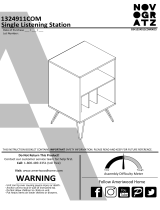 Dorel Home 1324911COM Assembly Manual
-
Ameriwood HD34376 Mode d'emploi
-
-
 Dorel Home 1323911COM Assembly Manual
-
ROOMS TO GO 40813380 Assembly Instructions
-
-
 Dorel Home 2178096COM Assembly Manual
-
Ameriwood Home HD22697 Mode d'emploi


