Poulan 426140 Manuel utilisateur
- Catégorie
- Tondeuses à gazon
- Taper
- Manuel utilisateur
Ce manuel convient également à

03076
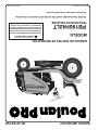
REPAIR PARTS MANUAL
MODEL:
PB195H42LT
LAWN TRACTOR
ALWAYS WEAR EYE PROTECTION DURING OPERATION
Visit our website: www.poulan-pro.com
WARNING:
Read this Man u al and follow all Warnings
and Safety Instructions. Fail ure to do so
can re sult in serious in ju ry.
IMPORTANT MANUAL DO NOT THROW AWAY
426140 02.16.09 TH Printed in the U.S.A.

2
HOW TO USE THIS MANUAL
This manual is designed to provide the customer with a means to identify the parts on his/her tractor
when ordering repair parts. The illustrations may or may not represent the actual assemblies; therefore,
it is not recommended to use this manual as a guide to assemble or disassemble the tractor. Some
hardware and parts are drawn larger in order to more readily identify them.
Each tractor has its own model number.
The model number for your tractor can be found on the fender under the seat.
When ordering parts, always give the following information:
• Product - “TRACTOR”
• MODEL NUMBER - “PB195H42LT (96042003604)”
• Part Number
• Part Description
TABLE OF CONTENTS
SCHEMATIC ................................................................................................................ 3
ELECTRICAL ............................................................................................................4-5
CHASSIS ..................................................................................................................6-7
DRIVE........................................................................................................................8-9
ENGINE .................................................................................................................10-11
STEERING .................................................................................................................12
SEAT ..........................................................................................................................13
MOWER DECK .....................................................................................................14-15
MOWER LIFT .............................................................................................................16
DECALS .....................................................................................................................17
WARRANTY ...........................................................................................BACK COVER

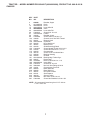
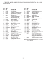
3
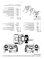
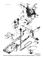
M
FUSE
STARTER
SOLENOID
BATTERY
CLUTCH/BRAKE
(PEDAL UP)
REVERSE SWITCH
(NOT IN REVERSE)
SEAT SWITCH
(NOT OCCUPIED)
SHORTING
CONNECTOR
CHASSIS
HARNESS
IGNITION
UNIT
HOUR
METER
CHASSIS HARNESS
CONNECTOR
(MATING SIDE)
DASH HARNESS
CONNECTOR
(MATING SIDE)
FUEL
LINE
FUEL SHUT-OFF
SOLENOID
(IF SO EQUIPPED)
JUNCTION
CONNECTOR
S
M
B
G
L
2
3
1
6
A2
A1
M
63
52
41
6
5
4
3
2
1
SPARK
PLUGS GAP
(2 PLUGS ON
TWIN CYL. ENGINES)
(OPTIONAL)
NON-REMOVABLE
CONNECTIONS
REMOVABLE
CONNECTIONS
WIRING INSULATED CLIPS
NOTE: IF WIRING INSULATED
CLIPS WERE REMOVED FOR
SERVICING OF UNIT, THEY
SHOULD BE RE-INSTALLED TO
PROPERLY SECURE YOUR
WIRING.
SCH11
IGNITION SWITCH
CIRCUIT
POSITION
OFF
B+A1
RUN/OVERRIDE
B+S+A1START
M+G+A1
B+A1RUN
“MAKE”
L+A2
ATTACHMENT CLUTCH
(CLUTCH OFF)
BLACK
BLACK /WHITE
BLUE
BLUE
BLACK
BLACKBLACK
BLACK
BLACK
BLACK
BLACK
BLACK
DER
RED
WHITE
WHITE
GRAY
GRAY
BLACK
BLACK
POWER OUTLET
(OPTIONAL)
12V
BLACK
A
AMMETER
(OPTIONAL)
RED
BLACK
BROWN
HEADLIGHTS
LIGHT SWITCH
ORANGE
LIGHTING SYSTEM OUTPUT
5 AMP AC @ 3600 RPM
ALTERNATOR
14 VOLTS AC MIN. @ 3600 RPM (LIGHTS OFF)
DIODE
28 VOLTS AC MIN. @ 3600 RPM
(CHARGING SYSTEM DISCONNECTED)
CHARGING SYSTEM OUTPUT
3 AMP DC @ 3600 RPM
NOTE
YOUR TRACTOR IS
EQUIPPED WITH A SPECIAL
ALTERNATOR SYSTEM.
THE LIGHTS ARE NOT
CONNECTED TO THE
BATTERY, BUT HAVE THEIR
OWN ELECTRICAL SOURCE.
BECAUSE OF THIS, THE
BRIGHTNESS OF THE LIGHTS
WILL CHANGE WITH ENGINE
SPEED. AT IDLE THE LIGHTS
WILL DIM. AS THE ENGINE IS
SPEEDED UP, THE LIGHTS
WILL BECOME THEIR
BRIGHTEST.
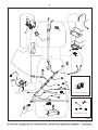
TRACTOR - - MODEL NUMBER PB195H42LT (96042003604), PRODUCT NO. 960 42 00-36
SCHEMATIC

4
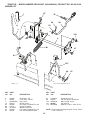
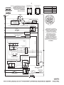
TRACTOR - - MODEL NUMBER PB195H42LT (96042003604), PRODUCT NO. 960 42 00-36
ELECTRICAL
30
33
34
22
79
21
41
42
26
43
27
40
71
16
87
25
T02S
90
28
55
With 12V Outlet Option
59
103
With Service Minder Option
4646
94
92
29
93
2

5
TRACTOR - - MODEL NUMBER PB195H42LT (96042003604), PRODUCT NO. 960 42 00-36
ELECTRICAL
KEY PART
NO. NO. DESCRIPTION
1 163465 Battery
2 74760412 Bolt Hex Hd 1/4-20 unc x 3/4
8 193228 Box Battery
16 176138 Switch Interlock
21 183759 Harness Socket Light
22 4152J Bulb, Light #1156
25 412894 Cable Battery
26 175158 Fuse
27 73510400 Nut Keps Hex 1/4-20 unc
28 198885 Cable Ground 18" Rear Battery Blk 6 Ga.
29 401545 Switch Seat
30 193350 Switch Ign
33 411935 Key/Chain
34 110712X Switch Light/Reset
40 401098 Harness Ign
41 17720408 Screw 1/4-20 unc x 1/2
42 131563 Cover Terminal Red
43 192507 Solenoid
55 17060512 Screw 5/16-18 x 3/4
71 400449 Harness Ign. Chass.
79 175242 Socket Asm. Bulb Twistlock
87 197802 Switch Interlock Clutch Cable
90 400725 Cover Terminal
92 196615 Harness Pigtail Console ROS
93 192540 Screw Plastic 10-14 x 2.0
94 191834 Modual Reverse ROS
NOTE: All component dimensions given in U.S. inches
1 inch = 25.4 mm

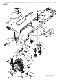
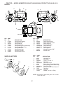
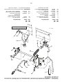
6
37
181
181
194
194
36
236
236
183
152
159
180
162
196
287
138
182
176
175
177
130
151
2
159
159
58
189
189
189
228
194
228
137
137
14
18
208
207
15
25
186
176
5
176
176
235
235
150
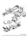
Chassis-tex_elite-sv-pro_11_r2
TRACTOR - - MODEL NUMBER PB195H42LT (96042003604), PRODUCT NO. 960 42 00-36
CHASSIS

7
2 412280 Drawbar, Upper
5 197783X428 Dash
14 183393X428 Hood
15 183834X599 Lens Grille LH
18 183395X428 Grille
25 183835X599 Lens Grille RH
36 17060512 Screw 5/16-18 x 3/4
37 414872X428 Fender
58 412282 Drawbar, Lower
68 17490508 Screw Thdrol 5/16-18 x 1/2
130 416358 Screw #10 x 0.750 ROS Thread
137 184921 Bumper Hood
138 193224X428 Cupholder
150 184322 Duct Heat Hood
151 407807 Bracket Pivot
152 194329 Shield Browning/Debris
159 17000612 Screw Hexwsh Thdrol 3/8-16 x 3/4
162 142432 Screw Hex Wsh Hi-Lo 1/4 x 1/2
175 193243 Crossmember
176 400776 Screw 10-24 x 5/8 Wshd Qdrx
177 195228 Bushing Steering
180 194260 Chassis
181 193102X428 Bushing Mtg. Fender Crgo.
182 193057 Dash Lower
183 74780520 Bolt Fin Hex 5/16-18 x 1-1/4
186 183829X428 Insert Grille
189 17000512 Screw 5/16-18 x 3/4
194 73900500 Nut Lock Hex Flange 5/16-18
196 414581 Console Asm. Deck Lift
207 183833 Bezel Grille RH
208 183832 Bezel Grille LH
217 409167 Rod Pivot Chassis
228 195161 Stud Fastener
235 406129 Spacer Fender
236 73930500 Nut center Lock 5/16-18
287 17600406 Screw Hex Washead 1/4-20 x 3/8
TRACTOR - - MODEL NUMBER PB195H42LT (96042003604), PRODUCT NO. 960 42 00-36
CHASSIS
NOTE: All component dimensions given in U.S. inches
1 inch = 25.4 mm
KEY PART
NO. NO. DESCRIPTION

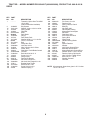
8
56
185
185
51
231
170
165
161
166
2
183
205
205
37
33
drive-tex_T2_fender_12
1
2
99
153
190
279
153
184
221
42
29
159
64
188
35
167
160
159
15
17
232
233
175
23
166
176
178
174
22
73
116
73
116
186
189
49
187
50
51
52
51
114
122
121
80
125
125
70
74
TRACTOR - - MODEL NUMBER PB195H42LT (96042003604), PRODUCT NO. 960 42 00-36
DRIVE

9
KEY PART
NO. NO. DESCRIPTION
TRACTOR - - MODEL NUMBER PB195H42LT (96042003604), PRODUCT NO. 960 42 00-36
DRIVE
NOTE: All component dimensions given in U.S. inches
1 inch = 25.4 mm
KEY PART
NO. NO. DESCRIPTION
1 - - - - - - Transaxle, Hydro Gear T2-AABC-
1X1A-1GX1
(Internal Parts Not Available)
2 123583X Key Square
15 19131316 Washer 13/32 x 13/16 x 16 Ga.
17 197296 Spring, Brake
22 197660 Rod Shift
23 409154X421 Knob
29 423239 Rod, Brake
33 12000001 Ring E
35 197722 Rod, Brake, Park
37 121749X Washer 25/32 x 1-1/4 x 16 Ga.
42 8883R Cover, Foot Pedal
49 72110614 Bolt
50 194327 Pulley Idler Flat
51 73900600 Lock Nut 3/8-16
52 194326 Idler V-Groove 910" Offset
56 125907X V-Belt, Drive
64 196200 Shaft Asm. Pedal Brake Control
70 193220X428 Console
73 74490544 Bolt Hex 5/16-18 Gr. 5
74 142432 Screw 1/4 x 1/2
80 408393 Strap Torque
99 408418 Rod Spring Bypass
114 73800500 Nut Lock 5/16-18 unc
116 73900500 Nut Lock Hex Flange 5/16-18
121 175611 Bracket Strap Torque
122 72010520 Bolt 5/16-18 x 2.50
125 17000512 Screw 5/16-18 x 3/4
153 4497H Retainer Spring 1"
159 76020412 Pin Cotter 1/8 x 3/4
160 169484 Retainer Clip
161 105709X Spring, Return, Clutch
165 196212 Bushing
166 197290 Nut Push .625
167 405257 Latch Brake Parking
170 413430 Keeper Belt Centerspan
174 197289 Nut Push
175 408539 Shaft Asm Shift
176 196214 Arm Clevis Rod Shift
178 197456 Spring Shift
183 156972 Spacer Axle
184 198403X505 Handle Parking Brake
185 72110622 Bolt
186 194321 Spacer Retainer
187 19133210 Washer
188 194323 Link Clutch Ground Drive
189 194317 Bellcrank Ground Drive
190 194318 Keeper Bellcrank Ground Drive
205 121748X Washer 25/32 x 1-5/8 x 16 Ga.
221 403187 Retainer Spring Clip Handle
231 407287 Idler V-Groove 1.688" Offset
232 74780716 Bolt 7/16-14 x 1 Gr 5
233 405296 Washer Serrated
279 408538 Link Shift

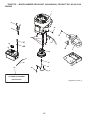
10
21
20
OPTIONAL EQUIPMENT
Spark Arrester
29
18
15
37
28
engine-bs-1cyl-tex_4
12
42
85
9
90
84
45
1
81
82
69
2
79
97
96
TRACTOR - - MODEL NUMBER PB195H42LT (96042003604), PRODUCT NO. 960 42 00-36
ENGINE

11
1 - - - - - - Engine B&S Model No. 31P677
2 137352 Muffler
9 194319 Keeper Belt Engine
12 401985 Pulley Engine
15 407545 Tank Fuel 1.50
18 425162 Cap Asm
20 176636X421 Control Throttle/Choke
21 416358 Screw #10 x 0.750 BOS Thread
28 401137 Fuel Line
29 137180 Spark Arrester Kit
37 123487X Clamp Hose
42 10040700 Washer Lock 7/16
45 73510400 Nut Keps Hex 1/4-20 unc
69 165291 Gasket
79 192334 Screw Socket Hd 5/16-18 x .75
81 148456 Tube Drain Oil Easy
82 181654 Plug Drain Oil
84 17060620 Screw 3/8-16 x 1-1/4
85 173937 Bolt Hex 7/16-20 x 4 x Gr. 5-1.5
90 17000616 Screw 3/8-16 x 1.0
96 19091416 Washer 9/32 x 7/8 x 16 Ga.
97 17670412 Screw 1/4 - 20 x 3/4
TRACTOR - - MODEL NUMBER PB195H42LT (96042003604), PRODUCT NO. 960 42 00-36
ENGINE
KEY PART
NO. NO. DESCRIPTION
NOTE: All component dimensions given in U.S. inches
1 inch = 25.4 mm
Engine Power Rating Information
The gross power rating for individual gas engine models is labeled in accordance with SAE (Society of Automotive Engi-
neers) code J11940 (Small Engine Power & Torque Rating Procedure), and rating performance has been obtained and
corrected in accordance with SAE J1995 (Revision 2002-5). Actual gross engine power will be lower and is affected by,
among other things, ambient operating conditions and engine-to-engine variability. Given both the wide array of prod-
ucts on which engines are placed and the variety of environmental issues applicable to operating the equipment, the gas
engine will not develop the rated gross power when used in a given piece of power equipment (actual “on-site” or net
horsepower). This difference is due to a variety of factors including, but not limited to, accessories (air cleaner, exhaust,
charging, cooling, carburetor, fuel pump, etc.), application limitations, ambient operating conditions (temperature, humid-
ity, altitude), and engine-to-engine variability. Due to manufacturing and capacity limitations, Briggs & Stratton may sub-
stitute an engine of higher rated power for this Series engine.

12
55
35
19
60
59
58
67
54
67
78
66
54
65
61
55
2
steering-tex_LEGND2_26_r1
6
5
13
13
53
8
62
4
50
50
70
65
68
69
15
15
14
14
6
16
28
28
13
22
64
20
26
1
21
71
72
33
45
74
9
8
74
7
9
8
7
74
74
63
57
57
63
1 414803X428 Wheel, Steering
2 418168 Axle Asm., Front
4 403087 Spindle Asm., LH
5 403088 Spindle Asm., RH
6 6266H Bearing, Race Thrust Harden
7 121748X Washer 25/32 x 1-5/8 x 16 Ga.
8 12000029 Ring, Clip #T5304-75
9 121232X Cap, Spindle
13 121749X Washer 25/32 x 1-1/4 x 16 Ga.
14 10040600 Washer Lock 3/8
15 73540600 Nut, Crown Lock 3/8-24 unf
16 408220 Shaft Steering
19 194729 Plate Steering
20 198375X428 Boot, Steering
21 186737 Adapter, Wheel Steering
22 194845 Bushing, Strg. Blk
26 414854X428 Insert, Wheel Steering
28 17000612 Screw 3/8-16 x 3/4
33 10040500 Washer Lock 5/16
35 194732 Gear, Sector Plate
45 19113812 Washer 11/32 x 2-3/8 x 12 Ga.
50 73900600 Nut Lock Flg 3/8-16 unc
53 188967 Washer Hardened .793 x 1.637 x .060
54 74760636 Bolt Hex HS 3/8-16 unc x 2-1/4
55 414736 Spacer Brace Axle
57 407465 Bracket Upstop
58 194747 Bolt Shoulder Sector Pivot CFM
59 194748 Washer Thrust Sector Steering
60 73971000 Nut Flange Lock 5/8-11
61 194740 Draglink, LH
62 194741 Draglink, RH
63 17000512 Screw 5/16-18 x 3/4
64 199849 Retainer Clip Spring Steering
65 194734 Brace Axle Front
66 71020748 Bolt Hex Fghd 7/16-14 x 3 Serr
67 194737 Bushing PM Front Axle
68 73900700 Nut Lock Flange 7/16-14 Gr. 5
69 199162 Washer 1.5 x .505 x .118
70 196197 Bracket Deck Susp. Front
71 196075 Shaft Ext. Steering
72 74780572 Bolt 5/16-18 x 4.5 Gr. 5
74 3366R Bearing
78 57079 Washer Thrust .515 x .750 x .033
TRACTOR - - MODEL NUMBER PB195H42LT (96042003604), PRODUCT NO. 960 42 00-36
STEERING
NOTE: All component dimensions given in U.S. inches
1 inch = 25.4 mm
KEY PART
NO. NO. DESCRIPTION
KEY PART
NO. NO. DESCRIPTION

13
2
6
1
40
10
37
37
21
21
3
41
7
8
7
8
8
8
seat-tex_6.5SL_2
44
43
1 197514 Seat
2 180166 Bracket Pivot Fender
3 140675 Strap, Asm Fender
6 73800600 Nut, Lock w/Ins. 3/8-16 unc
7 124181X Spring, Seat Cprsn
8 171877 Bolt 5/16-18 unc x 3/4 w/Sems
10 196977 Pan, Seat
21 171852 Bolt, Shoulder 5/16-18
37 73800500 Nut, Lock 5/16-18 unc
40 197661 Handle Slide
41 198200 Spring Latch
43 74760612 Bolt 3/8-16 unc x 3/4
44 19133812 Washer 13/32 x 2 3/8 x 12 Ga.
TRACTOR - - MODEL NUMBER PB195H42LT (96042003604), PRODUCT NO. 960 42 00-36
SEAT
KEY PART
NO. NO. DESCRIPTION
KEY PART
NO. NO. DESCRIPTION
NOTE: All component dimensions given in U.S. inches
1 inch = 25.4 mm

14
TRACTOR - - MODEL NUMBER PB195H42LT (96042003604), PRODUCT NO. 960 42 00-36
MOWER DECK
30
30
42
43
60
38
63
46
147
55
64
47
192
56
56
57
62
188
189
1
69
21
21
69
69
20
40
145
42_D_man-tex_LT_19
21
24
25
26
27
29
23
189
188
144
36
113
113
40
57
19
19
6
6
117
116
118
119
117
119
116
118
30
30
32
38
31
33
34
59
68
195
122
123
195
242
241
15
14
13
11
8
16
70
7
7
37
67
152

15
1 196495 Mower Housing
6 195186 Arm Suspension
7 416358 Screw #10 x 0.750 BOS Thread
8 193003 Bolt/Washer Asm 7/16-20 unf
- - 139775 Blade, 42" Mulching Premium
(For better wear when mulching)
11 138971 Blade, 42" Hi-Lift
(For bagging or discharge)
- - 134149 Blade, 42" Mulching Std
(For mulching mowers only)
13 192872 Shaft Assembly, Mandrel
14 187281 Housing, Mandrel
15 110485X Bearing, Ball, Mandrel
16 174493 Stripper, Mower Deck
19 196539 Bolt, Shoulder
20 159770 Baffle, Vortex
21 73680500 Nut, Crownlock 5/16-18 unc
23 192557 Bracket, Deflector
24 105304X Cap, Sleeve
25 197026 Spring, Torsion, Deflector
26 110452X Nut, Push
27 193108X428 Shield, Deflector
29 131491 Rod, Hinge
30 173984 Screw Thdrol Rolling Wsh Hd
31 187690 Washer, Spacer
32 197473 Pulley, Mandrel
33 400234 Nut, Toplock, Flanged
34 72110612 Bolt Carr Sh. 3/8-16 x 1-1/2 Gr. 5
36 197379 Pulley, Idler 4.50 RAW
37 19131316 Washer 13/32 x 13/16 x 16 Ga.
38 199189 Keeper Belt LH Mandrel
40 73900600 Nut, Lock Flg. 3/8-16 unc
42 197256 Spring Torsion Retainer
43 198410 Spring Torsion Brake
46 137729 Screw Thd Roll 1/4-20 x 5/8
47 197250 Bracket Clutch Cable
55 197249 Arm, Idler
56 199092 Spacer, Retainer
57 17000616 Screw Hexwsh Thd 3/8-16 x 1
59 141043 Guard, Tuv Idler (94)
60 197261 Arm Brake Mower
62 72110616 Bolt Rdhd Sqnk 3/8-16 unc x 2
63 199477 Arm Brake Mower
64 199790 Linkage Brake
67 198398X421 Handle, Clutch Cable
68 197253 V-Belt
69 72140505 Bolt Rdhd Sqnk 5/16-18 x 5/8
70 198332 Clutch Asm. Manual
113 17000510 Screw 5/16-18
116 4898H Bolt
117 188606 Wheel Gauge
118 73930600 Nut Lock 3/8-16 unc
119 19121414 Washer 3/8-7/8 x 14 Ga.
122 197258 Keeper Belt Eng. LH
123 197259 Keeper Belt Eng. RH
144 199204 Keeper Belt
145 193197 Pulley Idler Primary
147 401971 Spring Return
152 408714 Cable Clutch Manual w/Spr.
188 195161 Stud Fastener
189 73900500 Nut Lock Hex Flange
192 197260 Bracket Brake Stand LH
195 17000612 Screw Hexwsh Thdr 3/8-16 x 3/4
241 152927 Vis
242 415598 Port, Washout
- - 192870 Mandrel Assembly (Includes
housing, shaft assembly, and
bearing only - pulley/nut/washer
and blade bolt/washers not
included)
- - 199608 Replacement Mower, Complete
TRACTOR - - MODEL NUMBER PB195H42LT (96042003604), PRODUCT NO. 960 42 00-36
MOWER DECK
KEY PART
NO. NO. DESCRIPTION
KEY PART
NO. NO. DESCRIPTION
NOTE: All component dimensions given in U.S. inches
1 inch = 25.4 mm

16
7
3
87
10
88
2
113
90
87
98
97
97
lift-tex_11_r1
91
101*
89
87
100
*Key 91 may be substituted for Key 101
2 195223 Shaft Asm., Lift
3 195231 Lever Asm., Lift RH
7 196492X421 Grip, Lever
10 196314 Spring Torsion
87 194209 Pin Cotter 7/16 Bow Tie Lock
88 410710 Spring Lift Assist
89 19191912 Washer Clear Zinc
90 194208 Pin Cotter 5/16 Bow Tie Lock
91 195181 Link Lift Susp Mower Rear
97 17000612 Screw 3/8-16 x .75
98 195270 Link Lift Susp. Front Mower
100 73930600 Nut Lock 3/8-16 unc
101 407003 Link Asm lift
113 19171912 Washer 17/32 x 1-3/6 x 12 Ga.
TRACTOR - - MODEL NUMBER PB195H42LT (96042003604), PRODUCT NO. 960 42 00-36
MOWER LIFT
KEY PART
NO. NO. DESCRIPTION
NOTE: All component dimensions given in U.S. inches
1 inch = 25.4 mm
KEY PART
NO. NO. DESCRIPTION

17
TRACTOR - - MODEL NUMBER PB195H42LT (96042003604), PRODUCT NO. 960 42 00-36
DECALS
NOTE: All component dimensions given in U.S. inches
1 inch = 25.4 mm
KEY PART
NO. NO. DESCRIPTION
6
2
1
5,8
4,10
3,9
11
7
WHEELS AND TIRES
KEY PART
NO. NO. DESCRIPTION
KEY PART
NO. NO. DESCRIPTION
3
16
9
1 59192 Cap Valve Tire
2 65139 Stem Valve
3 106222X Tire F T 15 x 6 0 - 6
4 59904 Tube Front
5 106732X421 Rim Asm 6" Front
6 278H Fitting Grease (Front Wheel Only)
7 9040H Bearing Flange (Front Wheel Only)
8 106108X421 Rim Asm 8" Rear
9 420531 Tire R T 18 x 9.5-8 Turf Saver LT
10 7152J Tube Rear
11 104757X421 Cap Axle
- - 144334 Sealant, Tire (10 oz. Tube)
20
14
1 411658 Decal Fender Warning
2 408834 Decal Engine H.P.
3 186164 Decal Hood LH
4 408794 Decal Side Panel
6 170563 Decal Warning, Keep Hand Away
7 411629 Decal Replacement Parts
8 411175 Decal LWRDASH
9 172740 Decal Fender Logo
11 423398 Decal Ins Strg Whl
12 408948 Decal Fender SD RH
1
13 408949 Decal Fender SD LH
14 160396 Decal V-Belt Schematic
16 186163 Decal Hood RH
20 145005 Decal Bat Dan/Psn
- - 193226X428 Pad Footrest LH
- - 193277X428 Pad Footrest RH
- - 166960 Decal Bypass
- - 411287 Manual Operator's E&F
- - 426140 Manual Parts
7
11
4
4
6
8
13
8
12
2

LIMITED WARRANTY
The Manufacturer warrants to the original consumer purchaser that this product as manufactured is free from defects in materi-
als and work man ship. For a period of two (2) years from date of purchase by the original consumer purchaser, we will repair or
replace, at our option, without charge for parts or labor incurred in replacing parts, any part which we find to be defective due
to materials or workmanship. This Warranty is subject to the following limitations and exclusions.
1. This warranty does not apply to the engine, transaxle/transmission components, battery (except as noted below) or com-
ponents parts thereof. Please refer to the applicable manufacturer's warranty on these items.
2. Transportation charges for the movement of any power equipment unit or attachment are the responsibility of the pur chas-
er. Transportation charges for any parts submitted for replacement under this warranty must be paid by the purchaser un-
less such return is requested by the manufacturer.
3. Battery Warranty: On products equipped with a Battery, we will replace, without charge to you, any battery which we find
to be defective in manufacture, during the first ninety (90) days of ownership. After ninety (90) days, we will exchange the
Battery, charging you 1/12 of the price of a new Battery for each full month from the date of the original sale. Battery must
be maintained in accordance with the instructions furnished.
4. The Warranty period for any products used for rental or commercial purposes is limited to 90 days from the date of original
purchase.
5. This Warranty applies only to products which have been properly assembled, adjusted, operated, and main tained in ac -
cor dance with the instructions furnished. This Warranty does not apply to any product which has been subjected to altera-
tion, misuse, abuse, improper assembly or installation, delivery damage, or to normal wear of the product.
6. Exclusions: Excluded from this Warranty are belts, blades, blade adapters, normal wear, normal adjustments, stan dard
hardware and normal maintenance.
7. In the event you have a claim under this Warranty, you must return the product to an authorized service dealer.
Should you have any unanswered questions concerning this Warranty, please contact:
giving the model number, serial number and date of purchase of your product and the name and address of the authorized
dealer from whom it was purchased.
THIS WARRANTY DOES NOT APPLY TO INCIDENTAL OR CONSEQUENTIAL DAMAGES AND ANY IMPLIED WAR RAN -
TIES ARE LIMITED TO THE SAME TIME PERIODS STATED HEREIN FOR OUR EXPRESSED WARRANTIES. Some areas
do not allow the limitation of consequential damages or limitations of how long an implied Warranty may last, so the above limi-
tations or exclusions may not apply to you. This Warranty gives you specific legal rights, and you may have other rights which
vary from locale to locale.
This is a limited Warranty within the meaning of that term as defined in the Magnuson-Moss Act of 1975.
In Canada contact:
HOP
5855 Terry Fox Way
Mississauga, Ontario
L5V 3E4
HOP
Outdoor Products Customer Service Dept.
1030 Stevens Creek Road
Augusta, GA 30907 USA

GARANTIE LIMITÉE
Le Fabricant garantit à l’acheteur initial que son produit tel que manufacturé est libre de défaut de matière et d’ouvrage. Pendant
deux (2) ans, à compter de la date d’achat de la part de l’acheteur initial, nous réparerons où remplacerons à notre choix, gra-
tuitement, toute pièce, sur laquelle nous estimerons qu’il existe un défaut de matière ou d’ouvrage. Cette garantie est soumise
aux limitations et exceptions suivantes:
1. Cette garantie ne couvre pas le moteur, la transmission/composants, la batterie (sauf comme mentionnée ci-dessous) ou
les pièces detachées. Veuillez-vous consulter la garantie applicable du fabricant des articles.
2. L'acheteur est responsable des frais du transport de tous les équipements actionnés par moteur ou les accessoires. L'acheteur
est responsable des frais aussi du transport de toutes les pièces (couvertes par cette garantie) soumis pour le remplacement
à moins que manufacturé demande à l'acheteur de renvoyer les pièces.
3. Garantie de la batterie: Pour les produits équipés d’une batterie, nous remplacerons, gratuitement, toute batterie estimée
défectueuse pendant les quatre-vingt-dix (90) jours initiaux suivant l’achat. Après quatre-vingt-dix (90) jours, nous échan-
gerons la batterie, le coût pour vous être 1/12 du prix d'une nouvelle batterie pour chaque mois complet à compter de la
date d'achat initiale. La batterie doit être entretenue selon les directives données dans la documentation appropriée.
4. La période de garantie applicable aux produits proposés en location ou à des fins commerciales est limitée à quatre-vingt-
dix (90) jours à compter de la date d’achat initiale.
5. Cette garantie ne s’applique qu’aux produits correctement montés, réglés, utilisés et entretenus conformément aux ins-
tructions données dans la documentation appropriée. Cette garantie ne s’applique pas aux produits qui ont été modifiés,
utilisés incorrectement, abusés, mal assemblés, mal installés ou avariés lors de la livraison ou usage normal.
6. Exclusions: Les courroies, les lames, les adaptateurs de lame, l’usage normal, les réglages normaux, la visserie standard,
et l’entretien normal sont exclus de cette garantie.
7. En cas de problème entrant dans le cadre de cette garantie, veuillez-vous retourner votre machine à un concessionnaire
autorisé.
Si vous auriez aucune question sans réponse concernant cette garantie, s’il vous plaît contactez:
HOP
Outdoor Products Customer Service Dept.
1030 Stevens Creek Road
Augusta, GA 30907 USA
en nous donnant le numéro du modèle, le numéro de série, la date d’achat de votre machine ainsi que l’adresse du concession-
naire autorisé chez qui vous l’avez acheté.
CETTE GARANTIE NE COUVRE AUCUN DOMMAGE INCIDENTEL OU CONSÉQUENT ET TOUTE GARANTIE IMPLICITE
EST LIMITÉE AUX MÊMES PÉRIODES PRÉCISÉES ICI POUR LES GARANTIES EXPLICITES DU FABRICANT. Certaines
localités ne permettent aucune restriction des dommages conséquents ou de la durée d’une garantie implicite et; par conséquent,
il se pourrait que les restrictions et exclusions énoncées ci-dessus ne s’appliquent pas à vous. Cette garantie vous donne droits
légaux spécifiques et vous pouvez aussi jouir d’autres droits d’un endroit à un autre.
Cette garantie est une garantie limitée comme définie dans la loi Magnuson-Moss Act de 1975.
Au Canada:
HOP
5855 Terry Fox Way
Mississauga, Ontario
L5V 3E4

17
TRACTEUR - - NUMÉRO DE MODÈLE PB195H42LT (96042003604), NO. DE PRODUIT 960 42 00-36
DÉCALCOMANIE
3
16
9
8
13
20
14
1
7
11
4
4
1 411658 Décalcomanie avertissement du aile
2 408834 Décalcomanie du motour H.P.
3 186164 Décalcomanie du capot
4 408794 Décalcomanie du panneau latéral
6 170563 Décalcomanie d'avertissement
7 411629 Décalcomanie de 8 411175 Décalco-
manie de LWRDASH
9 172740 Décalcomanie de l'aile Husqvarna
11 423398 Décalcomanie de insert
12 408948 Décalcomanie de Pare-chocs SD C.D.
NO. NO
DE DE
RÉF. PIÈCE DESCRIPTION
NO. NO
DE DE
RÉF. PIÈCE DESCRIPTION
13 408949 Décalcomanie de Pare-chocs SD C.G.
14 160396 Décalcomanie de la courroie rapézoïdale
16 186163 Dècalcomanie du capot
20 145005 Décalcomanie de danger/poison de la
batterie
- - 166960 Décalcomanie
- - 193226X428 Coussin d'repose-pied C.G.
- - 193277X428 Coussin d'repose-pied C.D.
- - 411287 Manuel du propriétaire (anglais/français)
- - 426140 Manuel de pièces
NO. NO
DE DE
RÉF. PIÈCE DESCRIPTION
1 59192 Capuchon de la valve du pneu
2 65139 Tubulure de la valve
3 106222X Pneu antérieur 15 x 6 0 - 6
4 59904 Chambre à air antérieure
5 106732X421 Ensemble de la jante antérieure de 6"
6 278H Graisseur (roue antérieure seulement)
7 9040H Palier à bride (roue antérieure seulement)
8 106108X421 Ensemble de la jante arrière de 8"
9 420531 Pneu arrière R T 18 x 9.5-8 Turf Saver LT
10 7152J Chambre à air arrière
11 104757X421 Chapeau de l’essieu
- - 144334 Joint d'étanchéité de pneu (tube de
.30L [10 oz. Tube])
ROUES & PNEUS
6
2
1
5,8
4,10
3,9
11
7
REMARQUE: Toutes les dimensions de composant sont don-
nées en pouces É.-U. --1 pouce = 25,4 mm
6
2
8
12
La page est en cours de chargement...
La page est en cours de chargement...
La page est en cours de chargement...
La page est en cours de chargement...
La page est en cours de chargement...
La page est en cours de chargement...
La page est en cours de chargement...
La page est en cours de chargement...
La page est en cours de chargement...
La page est en cours de chargement...
La page est en cours de chargement...
La page est en cours de chargement...
La page est en cours de chargement...
La page est en cours de chargement...
La page est en cours de chargement...
La page est en cours de chargement...
-
 1
1
-
 2
2
-
 3
3
-
 4
4
-
 5
5
-
 6
6
-
 7
7
-
 8
8
-
 9
9
-
 10
10
-
 11
11
-
 12
12
-
 13
13
-
 14
14
-
 15
15
-
 16
16
-
 17
17
-
 18
18
-
 19
19
-
 20
20
-
 21
21
-
 22
22
-
 23
23
-
 24
24
-
 25
25
-
 26
26
-
 27
27
-
 28
28
-
 29
29
-
 30
30
-
 31
31
-
 32
32
-
 33
33
-
 34
34
-
 35
35
-
 36
36


Poulan 426140 Manuel utilisateur
- Catégorie
- Tondeuses à gazon
- Taper
- Manuel utilisateur
- Ce manuel convient également à
Documents connexes
-
Poulan 96042006000 Manuel utilisateur
-
-
-
-
-
-
-
Poulan 96042004001 Manuel utilisateur
-
-
