Sony VPL-VW70 Le manuel du propriétaire
- Catégorie
- Projecteurs
- Taper
- Le manuel du propriétaire

VIDEO PROJECTOR
VPL-VW70
PROTOCOL MANUAL
1st Edition

VPL-VW70
! WARNING
This manual is intended for qualified service personnel only.
To reduce the risk of electric shock, fire or injury, do not perform any servicing other than that
contained in the operating instructions unless you are qualified to do so. Refer all servicing to
qualified service personnel.
! WARNUNG
Die Anleitung ist nur für qualifiziertes Fachpersonal bestimmt.
Alle Wartungsarbeiten dürfen nur von qualifiziertem Fachpersonal ausgeführt werden. Um die
Gefahr eines elektrischen Schlages, Feuergefahr und Verletzungen zu vermeiden, sind bei
Wartungsarbeiten strikt die Angaben in der Anleitung zu befolgen. Andere als die angegeben
Wartungsarbeiten dürfen nur von Personen ausgeführt werden, die eine spezielle Befähigung
dazu besitzen.
! AVERTISSEMENT
Ce manual est destiné uniquement aux personnes compétentes en charge de l’entretien. Afin
de réduire les risques de décharge électrique, d’incendie ou de blessure n’effectuer que les
réparations indiquées dans le mode d’emploi à moins d’être qualifié pour en effectuer d’autres.
Pour toute réparation faire appel à une personne compétente uniquement.

1
VPL-VW70
Table of Contents
1. Introduction
2. RS-232C
2-1. Communication Specifications .......................................... 1
2-2. Command Block Format .................................................... 2
2-3. Block Format ..................................................................... 3
2-4. Connection ......................................................................... 4
2-5. Communication Procedure ................................................ 4
2-5-1. Outline of Communication ....................................... 4
2-6. Communication Rules ....................................................... 5
2-7. Approximate Return Waiting Times ................................. 5
2-8. Other .................................................................................. 5
2-8-1. AMX Device Discovery ........................................... 5
Appendix


1
VPL-VW70
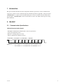
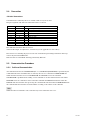
EVEN Parity ...... Total number of “1”s from D0 to D7 is an even number. 8 0
...... Total number of “1”s from D0 to D7 is an odd number. 8 1
D4 D5 D6 D7
(MSB)(LSB) (EVEN) BIT
PARITY STOP
BIT
START D3D2D1D0
1. Introduction
This protocol manual describes the basic configuration and basic operations of various commands used
for projector. Projector can be controlled using the commands provided in “Appendix”. Using an external
CONTROLLER , etc., inputs can be switched and the power can also be turned on and off. In the follow-
ing paragraphs, “CONTROLLER” means an external device such as a PC which controls projector using
these commands.
2. RS-232C
2-1. Communication Specifications
<RS-232C Communication Signal>
. Full duplex communication channels (Flow control not performed.)
. Start-stop synchronism system
. Baud rate: 38.4 kbps (bits per second)
. The bit configuration is defined as follows.
1 START Bit + 8 DATA Bits + 1 PARITY Bit + 1 STOP Bit

2
VPL-VW70
2-2. Command Block Format
The code from B0 to B7 as described below are transmitted.
START CODE : 0xA9
B0
B1
B2
B4
B3
DATA
ITEM NUMBER ACK / NAK ITEM NUMBER
SET / GET ACK
DUMMY DATA
CHECK SUM
END CODE : 0x9A
DATA
REPLY
B5
B6
B7
Transmission from
the Master side
Reception in
the Master side
Reception in the Master side
(With Data)
B0 START CORD
Common in the all FORMAT
B6 CHECK SUM
B1 to B5 are calculated by OR;
<Example of Calculation>
0xA9 1010 1001 0xA9 1010 1001
0xA9 1010 1001 0x9A 1001 1010
Answer 1010 1001 Answer 1011 1011
0xA9 0xBB
B7 END CODE
Common in the all FORMAT

3
VPL-VW70
2-3. Block Format
START CODE
B0
B1
B2
B4
B3
DATA
ITEM NUMBER
SET / GET
CHECK SUM
END CODE
B5
B6
B7
START CODEB0
B1
B2
B4
B3
DUMMY DATA
ACK / NAK
REPLY
CHECK SUM
END CODE
B5
B6
B7
START CODEB0
B1
B2
B4
B3
DATA
ITEM NUMBER
REPLY
CHECK SUM
END CODE
B5
B6
B7
Transmission from the Master side
Reception in the Master side
Reception in the Master side (With Data)
Data transmission to the Projector
Start of Command
Set the Data Category Value desired.
Refer to the Appendix Table 1 for details.
SET: 0x00 (Set data)
GET: 0x01 (Get data)
SET: Data to be set (Refer to the Appendix Table 2)
GET: Unused. Set Dummy data [0x00, 0x00]
Check Sum
End of Command
Receive results of the data transmission from the Projector.
Start of Command
Results correspond with the data transmission
Refer to the Appendix Table 3 for the data in detail.
[0x03]
Express Reply data either of ACK, or NAK
This data does not mean any senses.
Dummy Data [0x00, 0x00] is stored.
Check Sum
End of Command
Check Sum
End of Command
Receive data from the Projector
Start of Command
Data to acquire
Refer to the Appendix Table 1 in detail.
[0x02]
Express data to be Reply data
Received data
Refer to the Appendix Table 2 in detail.

4
VPL-VW70
2-5. Communication Procedure
2-5-1. Outline of Communication
All communication between CONTROLLER (PC, etc.) and DEVICE (PROJECTOR) is performed by the
command block format. Communication is started by the issue of a command at CONTROLLER and
ended when the return data is sent to CONTROLLER after DEVICE receives the command.
CONTROLLER is prohibited from sending several commands at one time. This means that after CON-
TROLLER sends one command, it cannot send other commands until DEVICE returns the return data.
DEVICE sends the return data after processing the command. The time from when CONTROLLER sends
the command until the return data is returned differs according to the contents of the command.
n
When Sircs Direct Command is sent, return data may not be returned in some cases.
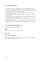
2-4. Connection
<RS-232C Connection>
Communication is enabled by the use of a D-Sub 9 Pin cross (reverse) cable.
The pin assignment of D-Sub 9 Pin and D-Sub 25 Pin is as follows.
Pins indicated as D-Sub 25 Pin are not used.
Assured cable length: 15 m (However, assurance may not be applicable for some cables.)
The software for controlling the projector from a PC is intended for performing transmission and recep-
tion for only the TxD and RxD lines.
Therefore there is no handshake normally performed by RS-232C.
D-Sub 9 Pin
Shell = FG
3
2
7
8
6
5
1
4
9
D-Sub 25 Pin
1
2
3
4
5
6
7
8
20
22
Name
FG
TxD
RxD
RTS
CTS
DSR
SG
DCD
DTR
RI
Grounding for safety protection or cable shield
Transmission data
Reception data
Transmission request
Transmission permission
Data set ready
GND for signal
Data channel signal carrier detection
Data terminal ready
Calling display (Presence/absence of calling signal)

5
VPL-VW70
2-6. Communication Rules
. When sending a command from CONTROLLER, the return data from PROJECTOR should be re-
ceived first before sending the next command. Even if the next command is sent before receiving the
return data, since PROJECTOR will not be able to receive that command, it does not return a response
to CONTROLLER. Consequently, no error code is also sent.
The following lists the approximate waiting times for PROJECTOR to return the return data after
CONTROLLER sends the command.
. When a communication error occurs, PROJECTOR ignores the data received until now, and set into the
reception standby state.
. For undefined commands or commends determined as invalid by PROJECTOR, PROJECTOR will
send the “NAK” return data to CONTROLLER .
. Take note that when data is written when the input signal of PROJECTOR is unstable, that data (value)
will not be incorporated.
. When INDEX specified SIRCS direct command is transmitted, leave an interval of 45 msec until the
next transmission. (Do not return the return data (ACK, NAK) when the SIRCS direct command is
received.)
2-7. Approximate Return Waiting Times
The await-return time is approx. 30 to 2200 msec.
n
This is the case, unless the communications are interfered anyway.
2-8. Other
2-8-1. AMX Device Discovery
This model is equipped with the protocol that conforms to the Device Discovery stipulated by AMX.
Contact AMX for details about the Device Discovery.

6
VPL-VW70
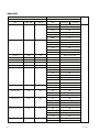
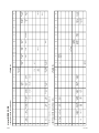
Appendix
<Table 1> <Table 2> Remarks
Item Number Data
Item Upper byte Lower byte Data Upper byte Lower byte
Input 00h 01h Video 00h Set/Get
S Video 01h
Input A 02h
Component 03h
HDMI1 04h
HDMI2 05h
Picture Mode 00h 02h Dynamic 00h
Standard 01h
Cinema 02h
User1 03h
User2 04h
User3 05h
Contrast 00h 10h 00h to 64h (0 to 100)
Brightness 00h 11h 00h to 64h (0 to 100)
Color 00h 12h 00h to 64h (0 to 100)
Hue 00h 13h 00h to 64h (0 to 100)
Sharpness 00h 14h Normal 00h to 64h (0 to 100)
ColTemp 00h 17h High 00h
Mid 01h
Low 02h
Custom1 03h
Custom2 04h
Custom3 05h
Custom4 06h
Lamp Control 00h 1Ah Low 00h
High 01h
Black Level Adj. 00h 1Ch Off 00h
Low 01h
High 02h
Advanced Iris 00h 1Dh Off 00h
Manual 01h
Auto1 02h
Auto2 03h
Real Color Processing 00h 1Eh Off 00h
User1 01h
User2 02h
User3 03h
Filme Mode 00h 1Fh Off 00h
Auto 02h

7
VPL-VW70
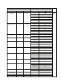
<Table 1> <Table 2> Remarks
Item Number Data
Item Upper byte Lower byte Data Upper byte Lower byte
Wide Mode 00h 20h Full 00h Set/Get
Normal 01h
Wide Zoom 02h
Zoom 03h
Full1 07h
Full2 08h
Anamorphic Zoom 0Bh
Gamma Correction 00h 22h Off 00h
Gamma 1 01h
Gamma 2 02h
Gamma 3 03h
Gamma 4 04h
Gamma 5 05h
Gamma 6 06h
Over Scan 00h 23h Off 00h
On 01h
Screen Area 00h 24h Full 00h
Through 01h
NR 00h 25h Off 00h
Low 01h
Middle 02h
High 03h
Block NR 00h 26h Off 00h
Low 01h
Middle 02h
High 03h
Mosquito NR 00h 27h Off 00h
Low 01h
Middle 02h
High 03h
Picture Muting 00h 30h Off 00h
On 01h
Input-A Signal Sel 00h 32h Auto 00h
Computer 01h
Component 02h
Video GBR 03h
Color Space 00h 3Bh Normal 00h
Wide 01h
USER GAIN RED 00h 50h FFE2h to 001Eh (_30 to 30)
USER GAIN GREEN 00h 51h FFE2h to 001Eh (_30 to 30)
USER GAIN BLUE 00h 52h FFE2h to 001Eh (_30 to 30)

8
VPL-VW70
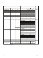
<Table 1> <Table 2> Remarks
Item Number Data
Item Upper byte Lower byte Data Upper byte Lower byte
USER BIAS RED 00h 53h FFE2h to 001Eh (_30 to 30) Set/Get
USER BIAS GREEN 00h 54h FFE2h to 001Eh (_30 to 30)
USER BIAS BLUE 00h 55h FFE2h to 001Eh (_30 to 30)
Iris Sensitivity 00h 56h Recommend 00h
Fast 01h
Slow 02h
Iris Manual 00h 57h 00h to 64h (0 to 100)
xvColor 00h 5Ah Off 00h
On 01h
Status Error 01h 01h NO ERROR 00h Get only
LAMP ERROR 01h
FAN ERROR 02h
COVER ERROR 04h
TEMP ERROR 08h
D5V ERROR 10h
POWER ERROR 20h
NVM Data ERROR 80h
25h LENS SHUTTER 01h
ERROR
Status Power 01h 02h STANBY 00h
START UP 01h
STARTUP LAMP 02h
POWER ON 03h
COOLING1 04h
COOLING2 05h
SAVING COOLING1 06h
SAVING COOLING2 07h
SAVING STABY 08h
Lamp Timer 01h 13h USE TIME 0000h-FFFFh
*1
Sircs (15bit category) 17h Refer to Table4 ----- 00h 00h Set only
*2
Sircs (20bit category) 19h Refer to Table5 ----- 00h 00h
1Bh Refer to Table6 ----- 00h 00h
*1 Example) In case the lamp timer indicates 1000H, return values are [03h] upper byte and [E8h] lower byte.
*2 It is corresponded to single command only.

9
VPL-VW70
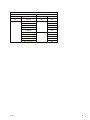
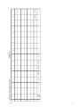
<Table 3>
Item Number Data
Item Data Upper byte Lower byte
ACK Complete 00h 00h
NAK Undefined Command 01h 01h
Size Error 04h
Select Error 05h
Range Over 06h
Not Applicable 0Ah
Check Sum Error F0h 10h
Framing Error 20h
Parity Error 30h
Over Run Error 40h
Other Comm Error 50h

10
VPL-VW70
List of SIRCS CODE
<15BIT PROJECTOR CATEGORY> <Table 4>
*1 Sent the command twice for [low] the standby mode.
<20BIT PROJECTOR-E CATEGORY> <Table 5>
RCP
7x
WIDE MODE
TOGGLE
6x
PHASE
ADJUST
PICTURE
TOGGLE
5x
4x
V
KEYSTONE
3x
2x
1x
xF
0x
xB xC xD xEx7 x8 x9 xA
xE xF
x0 x1 x2 x3 x4 x5 x6
xA xB xC xDx6 x7 x8 x9x0 x1 x2 x3 x4 x5
RESET
HDMI 1
S VIDEOENTER
INPUT
SELECT
PITCH SHIFT
POWER
OFF
→
→
CURSOR
←
←
CURSOR
↑
↑
CURSOR
↓
↓
CURSOR
INPUT A
HDMI 2
COMPONENT
POWER
ON
MENU VIDEO
STATUS
OFF
5x
6x
7x
HUE+
PURPLISH
SHARPNESS+
SHARP
SHARPNESS_
SOFT
PICTURE
MUTING
LENS
SHIFT
LENS
SHIFT
LENS
SHIFT
LENS
SHIFT
LENS FOCUS
FAR
LENS FOCUS
NEAR
LENS ZOOM
LARGE
LENS ZOOM
SMALL
STATUS
ON
2x
3x
4x
HUE_
GREENISH
KEYSTONE
_
KEYSTONE
V
V
+
CONTRAST+
HIGH
CONTRAST_
LOW
COLOR+
HIGH
COLOR_
LOW
BRITNESS+
BRIGHT
BRITNESS_
DARK
0x
POWER
ON/OF
TOGGLE
*1
*1
1x
APA
PICTURE
MODE
DYNAMIC
PICTURE
MODE
STANDARD
PICTURE
MODE
CINEMA
PICTURE
MODE
USER1
PICTURE
MODE
USER2
PICTURE
MODE
USER3
PICTURE
MODE
TOGGLE
BLACK LEVEL
COLOR
SPACE
TOGGLE
COLOR
TEMP
TOGGLE
Gamma
Collection
TOGGLE
IRIS MODE
TOGGLE
LENS
ZOOM
LENS
SHIFT
LENS
FOCUS
LENS
TOGGLE

11
VPL-VW70
<20BIT PROJECTOR-EE CATEGORY> <Table 6>
xE xFxA xB xC xDx6 x7 x8 x9x0 x1 x2 x3 x4 x5
EXITOPTIONS
SYNC
MENU PLAY STOP PAUSE PREVIOUS NEXT
ON/OFF
5x
6x
7x
FAST
REWIND
FAST
FORWARD
2x
3x
4x
0x
1x


VPL-VW70
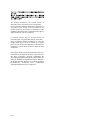
The material contained in this manual consists of
information that is the property of Sony Corporation.
Sony Corporation expressly prohibits the duplication of
any portion of this manual or the use thereof for any
purpose other than the operation or maintenance of the
equipment described in this manual without the express
written permission of Sony Corporation.
Le matériel contenu dans ce manuel consiste en
informations qui sont la propriété de Sony Corporation.
Sony Corporation interdit formellement la copie de
quelque partie que ce soit de ce manuel ou son emploi
pour tout autre but que des opérations ou entretiens de
l’équipement à moins d’une permission écrite de Sony
Corporation.
Das in dieser Anleitung enthaltene Material besteht aus
Informationen, die Eigentum der Sony Corporation sind.
Die Sony Corporation untersagt ausdrücklich die
Vervielfältigung jeglicher Teile dieser Anleitung oder den
Gebrauch derselben für irgendeinen anderen Zweck als
die Bedienung oder Wartung der in dieser Anleitung
beschriebenen Ausrüstung ohne ausdrückliche
schriftliche Erlaubnis der Sony Corporation.

English
Sony EMCS Corporation 2008JR16-1
Ichinomiya Tec ©2008
VPL-VW70 (UC) E
9-883-669-01
-
 1
1
-
 2
2
-
 3
3
-
 4
4
-
 5
5
-
 6
6
-
 7
7
-
 8
8
-
 9
9
-
 10
10
-
 11
11
-
 12
12
-
 13
13
-
 14
14
-
 15
15
-
 16
16
-
 17
17
-
 18
18


Sony VPL-VW70 Le manuel du propriétaire
- Catégorie
- Projecteurs
- Taper
- Le manuel du propriétaire
dans d''autres langues
- English: Sony VPL-VW70 Owner's manual
Autres documents
-
NEC PlasmaSync® 42VM1 Le manuel du propriétaire
-
Integra Computer Monitor PLA-50V1 Manuel utilisateur
-
Proxima ASA DP6850 Manuel utilisateur
-
 BOXLIGHT MP-650i Manuel utilisateur
-
Hitachi CPX970 Manuel utilisateur
-
Hitachi CP-X960E Manuel utilisateur
-
Fender Cyber-Twin SE Le manuel du propriétaire
-
Yamaha psr-5700 Le manuel du propriétaire
-
-
