Senco 10B0001N Le manuel du propriétaire
- Catégorie
- Outils électroportatifs
- Taper
- Le manuel du propriétaire

DS222-18V
DS225-18V
DS322-18V
AUTO-FEED
SCREWDRIVER
Operating Instructions
KYOCERA SENCO Industrial Tools
4270 Ivy Pointe Blvd.
Cincinnati, OH 45245
1-800-543-4596
www.senco.com
© 2019 by KYOCERA-SENCO Industrial Tools, Inc.
NFD810A10B10C • Issued November 4, 2019
IMPORTANT: Read before use.

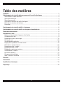
Table of Contents
Symbols .................................................................................................................................... 3
General Power Tool Safety Warnings ...................................................................................... 4
Work Area Safety ................................................................................................................... 4
Electrical Safety ..................................................................................................................... 4
Personal Safety ..................................................................................................................... 4
Power Tool Use and Care ...................................................................................................... 5
Battery Tool Use and Care ..................................................................................................... 5
Service .................................................................................................................................. 6
Screwdriver Safety Warnings .................................................................................................. 6
Safety Warnings for Charger and Battery ................................................................................ 6
Functional Description ............................................................................................................. 8
Tool Operation .......................................................................................................................... 9
Adjusting for Fastener Length ............................................................................................... 9
Loading the Tool .................................................................................................................... 9
Drive Speed Adjustment ...................................................................................................... 10
Driving Screws .................................................................................................................... 10
Trigger Lock ........................................................................................................................ 10
Depth of Drive Adjustment .................................................................................................. 10
Reverse Operation ............................................................................................................... 11
Bit Replacement .................................................................................................................. 11
Nosepiece Replacement ...................................................................................................... 12
Belt Hook Adjustment .......................................................................................................... 12
Battery Pack Installation ...................................................................................................... 12
Battery Pack Removal ......................................................................................................... 13
Battery Charging .................................................................................................................. 13
Battery Disposal .................................................................................................................. 14
Maintenance .......................................................................................................................... 14
Accessories ............................................................................................................................ 14
Technical Specifications ........................................................................................................ 15
Troubleshooting ..................................................................................................................... 16
2

3
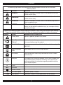
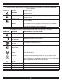
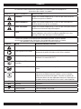
SYMBOLS
The following signal words and meanings are intended to explain the levels of risk associated
with this product.
SYMBOL SIGNAL MEANING
DANGER:
Indicates a hazardous situation, which, if not avoided, will result in
death or serious injury.
WARNING:
Indicates a hazardous situation, which, if not avoided, could result in
death or serious injury.
CAUTION:
Indicates a hazardous situation, which, if not avoided, may result in
minor or moderate injury.
NOTICE:
(Without Safety Alert Symbol) indicates information considered im-
portant, but not related to a potential injury (e.g. messages relating
to property damage).
Some of the following symbols may be used on this product. Please study them and learn their meaning.
Proper interpretation of these symbols will allow you to operate the product in a better, safer manner.
SYMBOL NAME DESIGNATION/EXPLANATION
Safety Alert
Indicates a potential personal injury hazard.
Read Operator’s
Manual
To reduce the risk of injury, user must read and understand opera-
tor’s manual before using this product.
Eye Protection
Always wear eye protection with side shields marked to comply with
ANSI Z87.1.
Wet Conditions
Alert
Do not expose to rain or use in damp locations.
No Hands
Failure to keep your hands away from blade will result in serious
personal injury.
Recycle
This product uses Lithium-ion batteries. Local, state, or federal laws
may prohibit disposal of batteries in ordinary trash. Consult your
local waste authority for information regarding available recycling
and or disposal options.
V Volts
Voltage
min Minutes
Time
Direct Current
Type or characteristic of current
n
o
No Load Speed
Rotational speed, at no load
.../min Per Minute
Revolutions, strokes, surface speed, orbits, etc. per minute

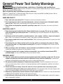
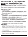
General Power Tool Safety Warnings
WARNING
Read all safety warnings, instructions, illustrations and specifications
provided with this power tool. Failure to follow all instructions listed below may result in electric
shock, fire and/or serious injury.
Save all warnings and instructions for future reference.
The term “power tool” in the warnings refers to your mains-operated (corded) power tool or
battery-operated (cordless) power tool.
WORK AREA SAFETY
1. Keep work area clean and well lit. Cluttered or dark areas promote accidents.
2. Do not operate power tools in explosive atmospheres, such as in the presence of flammable liquids,
gases or dust. Power tools create sparks which may ignite the dust or fumes.
3. Keep children and bystanders away while operating a power tool. Distractions can cause you to lose
control.
ELECTRICAL SAFETY
4. Power tool plugs must match the outlet. Never modify the plug in any way. Do not use any adapter
plugs with earthed (grounded) power tools. Unmodified plugs and matching outlets will reduce risk of
electric shock.
5. Avoid body contact with earthed or grounded surfaces, such as pipes, radiators, ranges and refrigera-
tors. There is an increased risk of electric shock if your body is earthed or grounded.
6. Do not expose power tools to rain or wet conditions. Water entering a power tool will increase the risk of
electric shock.
7. Do not abuse the cord. Never use the cord for carrying, pulling or unplugging the power tool. Keep
cord away from heat, oil, sharp edges or moving parts. Damaged or entangled cords increase the risk
of electric shock.
8. When operating a power tool outdoors, use an extension cord suitable for outdoor use. Use of a cord
suitable for outdoor use reduces the risk of electric shock.
9. If operating a power tool in a damp location is unavoidable, use a residual current device (RCD)
protected supply. Use of an RCD reduces the risk of electric shock.
PERSONAL SAFETY
10. Stay alert, watch what you are doing and use common sense when operating a power tool. Do not use
a power tool while you are tired or under the influence of drugs, alcohol or medication. A moment of
inattention while operating power tools may result in serious personal injury.
11. Use personal protective equipment. Always wear eye protection. Protective equipment such as dust
mask, non-skid safety shoes, hard hat, or hearing protection used for appropriate conditions will reduce
personal injuries.
12. Prevent unintentional starting. Ensure the switch is in the off position before connecting to power
source and/or battery pack, picking up or carrying the tool. Carrying power tools with your finger on the
switch or energizing power tools that have the switch on invites accidents.
13. Remove any adjusting key or wrench before turning the power tool on. A wrench or a key left attached to
a rotating part of the power tool may result in personal injury.
14. Do not overreach. Keep proper footing and balance at all times. This enables better control of the power
tool in unexpected situations.
4

15. Dress properly. Do not wear loose clothing or jewelry. Keep your hair, clothing and gloves away from
moving parts. Loose clothes, jewelry or long hair can be caught in moving parts.
16. If devices are provided for the connection of dust extraction and collection facilities, ensure these are
connected and properly used. Use of dust collection can reduce dust-related hazards.
17. Do not let familiarity gained from frequent use of tools allow you to become complacent and ignore tool
safety principles. A careless action can cause severe injury within a fraction of a second.
POWER TOOL USE AND CARE
18. Do not force the power tool. Use the correct power tool for your application. The correct power tool will do
the job better and faster at the rate for which it was designed.
19. Do not use the power tool if the switch does not turn it on and off. Any power tool that cannot be controlled
with the switch is dangerous and must be repaired.
20. Disconnect the plug from the power source and/or remove the battery pack, if detachable, from the pow-
er tool before making any adjustments, changing accessories, or storing power tools. Such preventive
safety measures reduce the risk of starting the power tool accidentally.
21. Store idle power tools out of the reach of children and do not allow persons unfamiliar with the power tool
or these instructions to operate the power tool. Power tools are dangerous in the hands of untrained users.
22. Maintain power tools and accessories. Check for misalignment or binding of moving parts, breakage of
parts and any other condition that may affect the power tool’s operation. If damaged, have the power
tool repaired before use. Many accidents are caused by poorly maintained power tools.
23. Keep cutting tools sharp and clean. Properly maintained cutting tools with sharp cutting edges are less
likely to bind and are easier to control.
24. Use the power tool, accessories and tool bits, etc. in accordance with these instructions, taking into
account the working conditions and the work to be performed. Use of the power tool for operations
different from those intended could result in a hazardous situation.
25. Keep handles and grasping surfaces dry, clean and free from oil and grease. Slippery handles and
grasping surfaces do not allow for safe handling and control of the tool in unexpected situations.
BATTERY TOOL USE AND CARE
26. Recharge only with the charger specified by the manufacturer. A charger that is suitable for one type of
battery pack may create a risk of fire when used with another battery pack.
27. Use power tools only with specifically designated battery packs. Use of any other battery packs may
create a risk of injury and fire.
28. When battery pack is not in use, keep it away from other metal objects, like paper clips, coins, keys,
nails, screws or other small metal objects, that can make a connection from one terminal to another.
Shorting the battery terminals together may cause burns or a fire.
29. Under abusive conditions, liquid may be ejected from the battery; avoid contact. If contact accidentally
occurs, flush with water. If liquid comes into contact with eyes, additionally seek medical help.
Liquid ejected from the battery may cause irritation or burns.
30. Do not use a battery pack or tool that is damaged or modified. Damaged or modified batteries may
exhibit unpredictable behaviour resulting in fire, explosion or risk of injury.
31. Do not expose a battery pack or tool to fire or excessive temperature. Exposure to fire or temperature
above 130 °C may cause explosion.
GENERAL POWER TOOL SAFETY WARNINGS
5

32. Follow all charging instructions and do not charge the battery pack or tool outside the temperature range
specified in the instructions. Charging improperly or at temperatures outside the specified range may
damage the battery and increase the risk of fire.
SERVICE
33. Have your power tool serviced by a qualified repair person using only identical replacement parts.
This will ensure that the safety of the power tool is maintained.
34. Never service damaged battery packs. Service of battery packs should only be performed by the manufac-
turer or authorized service providers.
Screwdriver Safety Warnings
1. Hold the power tool by insulated gripping surfaces, when performing an operation where the fastener
may contact hidden wiring. Fasteners that come into contact with a “live” wire may make exposed metal
parts of the power tool “live” and could give the operator an electric shock.
2. Do not use the power tool in locations where the ambient temperature may reach 0°C (32°F) or exceed
40˚C (105˚F).
Safety Warnings for Charger and Battery
1. This manual contains important safety and operating instructions for the SENCO battery charger VB0156
and VB0189. Use with approved Senco batteries stated on the charger label.
2. Before using the SENCO battery charger VB0156 and VB0189, read all instructions and cautionary mark-
ings on (1) battery charger, (2) battery, and (3) product using battery.
3. Do not expose charger to water, rain or snow.
4. Use indoors.
5. Use of an attachment not recommended or sold by the battery charger manufacturer may result in a risk of
fire, electric shock, or injury to persons.
6. To reduce risk of damage to electric plug and cord, pull by plug rather than cord when disconnecting
charger.
7. Make sure cord is located so that it will not be stepped on, tripped over, or otherwise subjected to damage
or stress.
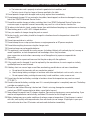
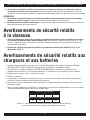
Length of Cord (Feet)
AWG Size of Cord
25 50 100 150
16 16 16 14
Table 1 - Recommended minimum AWG size for battery charger extension cords.
8. An extension cord should not be used unless absolutely necessary. Use of improper extension cord could
result in a risk of fire and electric shock. If extension cord must be used, make sure:
a. That pins on plug of extension cord are the same number, size, and shape as those of plug
on charger;
6
GENERAL POWER TOOL SAFETY WARNINGS

b. That extension cord is properly wired and in good electrical condition; and
c. That wire size is at least as large as the one specified in the table.
9. Do not operate charger with damaged cord or plug- replace them immediately.
10. Do not operate charger if it has received a sharp blow, been dropped, or otherwise damaged in any way;
take it to a SENCO Authorized Service Centre.
11. Do not disassemble charger or battery cartridge; take it to a SENCO Authorized Service Centre when
service or repair is required. Incorrect reassembly may result in a risk of electric shock or fire.
12. To reduce risk of electric shock, unplug charger from outlet before attempting any maintenance or cleaning.
13. Store battery packs in a 30%-50% charged condition.
14. Every six months of storage charge the pack as normal.
15. For best results, your battery should be charged in a location where the temperature is above 50˚F
but below 100˚F.
16. Do not store outside or in vehicles.
17. Do not attempt to use a step-up transformer, an engine generator or DC power receptacle.
18. Do not allow anything to cover or clog the charger vents.
19. Do not recharge non-rechargeable batteries.
20. This appliance is not intended for use by persons (including children) with reduced physical, sensory or
mental capabilities, or lack of experience and knowledge, unless they have been
given supervision or instructions concerning use of the appliance by a person responsible for
their safety.
21. Children should be supervised to ensure that they do no play with the appliance.
22. If the supply cord is damaged, it must be replaced by the manufacturer, its service agent or similarly
qualified persons to avoid a hazard.
23. A battery short can cause a large current flow, overheating, possible burns and even a breakdown.
a. Do not touch the terminals with any conductive material.
b. Avoid storing battery cartridge in a container with other metal objects such as nails, coins, etc.
c. Do not expose battery cartridge to excessively humid conditions, water, snow or rain.
24. Do not store the tool and battery cartridge in locations where the temperature may reach or exceed
27˚C (80˚ F).
25. Do not incinerate the battery cartridge even if it is severely damaged or is completely worn out. The battery
cartridge can explode in a fire.
26. Do not use tool without Warning Label on tool. If label is missing, damaged or unreadable,
contact your SENCO representative to obtain a new label at no cost.
27. Never attempt to connect two (2) chargers together. Consecutive charging may cause overheating. If you
need to recharge batteries consecutively, wait about 15 minutes for the charger to cool.
28. Battery leakage may occur under conditions of extreme usage or temperature. If liquid comes in contact
with skin, wash quickly with soap and water, then with lemon juice or vinegar. If liquid gets in your eyes,
wash with water for at least 10 minutes and seek medical attention immediately.
SAFETY WARNINGS FOR CHARGER AND BATTERY
7

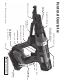
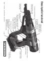
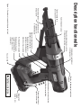
Tool-less Nosepiece
Adjustment Pin
Detachable Auto-Feed System
Locking Collar
LED Light
Variable Speed Trigger
Strip Guide Track
Drive Speed Adjustment
1600/2500 RPM
(Low Speed Tools Only)
Depth of Drive Adjustment Knob
Forward/Reverse Switch
Depth of Drive Lock Button
Slide Body Loading Point
Nosepiece Retention Screw
Strip Guide
(Only on DS322)
Depth of Drive Indicator
Bit Quick Release
Adjustable and
Reversible Belt Hook
18V Battery
(3Ah Shown)
Trigger Lock
Grasping Surface
Functional Description
Figure 1 - Tool Functions and Features

9
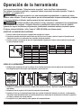
Tool Operation
Read sections titled “Safety Warnings” before operating tool.
For best results, charge new battery before using (see “Battery Charging” page #11).
WARNING
Do not use this product if it is not completely assembled or if any parts
appear to be missing or damaged. Use of a product that is not properly and completely
assembled or with damaged or missing parts could result in serious personal injury.
WARNING
Do not attempt to modify this product or create accessories or attachments not
recommended for use with this product. Any such alteration or modification is misuse
and could result in hazardous conditions possibly leading to serious personal injury.
I any parts are damaged or missing, please call 1-800-543-4596 for assistance.
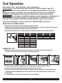
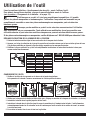
ADJUSTING FOR FASTENER LENGTH
1. Remove battery before adjusting nosepiece for fastener length.
2. Depress the screw selector pin until it is flush with nosepiece and slide the nosepiece to the desired
setting by aligning hatch marks with the silver adjustment pin.
3. Release pin and make sure it is fully engaged in selected nosepiece slot for proper operation
DS222-18V DS225-18V DS322-18V
1"
1 1/4"
1 1/2"
1 3/4"
1 5/8"
2"
1"
1 1/4"
1 1/2"
1 3/4"
1 5/8"
2"
1"
1 1/4"
1 1/2"
1 3/4"
1 5/8"
2"
2 1/4"
2 1/2"
2 3/4"
3"
Bit Type DS222/DS225 DS322
Phillips
Square
Rex
EA0297
EA0298
EA0299
EA0400
EA0401
EA0402
1
1-1/2
1-5/8
1-1/4
1-3/4
2
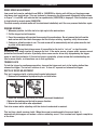
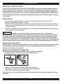
LOADING THE TOOL
1. Check to be sure the heads of the screws are resting on top of the plastic collation material.
This will ensure proper strip advancement and prevent jamming.
1 52
3
4
2. Check for proper fastener length setting (see “Adjusting for Fastener Length” above).
3. Feed the strip into the strip guide track up toward the nose of the tool.
4. Feed the strip into the slide body until the first screw is aligned with the bit. The tool will feed all
subsequent screws automatically as the tool is pulled back off the work surface, returning to its
relaxed state.
5. To remove the strip, pull it through from the top of the side body.

10
DRIVE SPEED ADJUSTMENT
Low speed tools can be switched from 2500 to 1600 RPM for driving self-drilling and tapping screws
into heavy steel applications. This can be done by depressing the drive speed adjustment button shown
in Figure 1. A red LED will indicate that low speed mode (1600 RPM) is engaged. Click the button again
to toggle back to normal mode (2500 RPM).
The most recently selected mode will be maintained indefinitely until the user presses the button again.
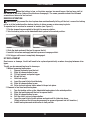
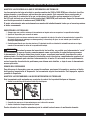
DRIVING SCREWS
1. Whenever possible, hold the tool at a right angle to the work surface.
2. Pull the trigger to start the motor.
3. Press the nosepiece with constant force against the work surface. Do not remove the tool from the
work surface until the clutch disengages and the bit stops rotating, signalling a fully driven screw.
4. Continue to allow the motor to run. The next screw will be automatically fed into place when the tool
is pulled off the work surface.
CAUTION
During the driving process it is possible for the tool to “cut-out” or stop the motor
prematurely as a safety function to preserve the tool. If the motor senses a torque spike, an over-current
protection function will activate. A partially driven screw can be driven fully by squeezing the trigger
again to reset the tool/motor. If this cut-out occurs repeatedly, please review the troubleshooting sec-
tion for more details, or discontinue use in that application.
TRIGGER LOCK
To lock the trigger for continuous operation, depress the trigger and push in the locking button then
release the trigger. The tool will continue to run. To turn off, squeeze and release the trigger.
DEPTH OF DRIVE ADJUSTMENT
This tool is equipped with a locking depth control adjustment:
1. Release the thumbwheel by depressing the red lock button.
2. Adjust the countersink by turning the depth adjustment thumbwheel.
3 Refer to the markings on the tool for proper direction.
4. Release the lock button after adjustment.
Test drive screws while adjusting until the desired countersink is reached.
This tool has a depth-sensing clutch. When the screw is countersunk to the preset depth, it
automatically disengages and makes a click or ratcheting sound. This is normal and signals completion
of the drive.
TOOL OPERATION

11
TOOL OPERATION
CAUTION
When the battery is low, or the drive requires too much torque, the tool may stall at
the bottom of the drive (before the clutch can disengage). The same procedure should be followed
as mentioned above for tool cut-out.
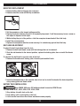
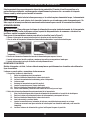
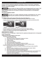
REVERSE OPERATION
WARNING
To prevent the feed system from unintentionally falling off the tool, ensure the locking
collar is at the locked position before starting to drive screws or when carrying tools.
To operate tool in reverse for removal of screws (see Figure 1):
1. Flip the forward/reverse switch to the right for reverse rotation.
2. Turn the locking collar on the detachable feed system to the unlock position.
Locked Unlocked
3. Slide the feed system off the tool to expose the bit.
4. Insert bit into screw and apply/maintain pressure to engage clutch.
5. Pull trigger until screw is completely disengaged.
BIT REPLACEMENT
Due to wear or damage, the bit will need to be replaced periodically or when changing between drive
types.
The bit can be removed/replaced in two ways:
1. Without removing feed system
i. Remove fasteners from the tool.
ii. Slide bit release button to rear.
iii. Tilt tool forward and pulse trigger.
iv. Bit will fall out.
v. Hold tool upright.
vi. Insert the new bit into the slide body.
vii. Slide bit release button to rear.
viii Pulse tool and release button when bit drops into place.
2. Removal of tool front end/feed system
i. Turn the locking collar on the detachable feed system to the unlock position.
ii. Slide the feed system off the tool to expose the bit.
iii. Slide bit release button to rear.
iv. Pull the old bit out and release button.
v. Insert the new bit into the bit retainer and push until it clicks into place.
(Slight rotation of the bit may be necessary for proper alignment and full insertion.)
vi. Install feed system and rotate collar to lock position.

12
TOOL OPERATION
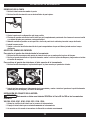
NOSEPIECE REPLACEMENT
1. Remove battery before changing the nosepiece.
2. Remove retention screw with flat-tip screwdriver.
3. Set the nosepiece on the longest setting possible.
4. Depress the screw selector pin until it is completely depressed. It will be necessary to use a screw or
thin object to depress to this depth.
5. While holding the pin in this position, slide the nosepiece forward and off the slide body
6. Install the new nosepiece.
7. Replace the nosepiece retention screw ensuring it is seated snug against the slide body.
BELT HOOK ADJUSTMENT
To adjust the belt hook offset from the tool:
1. Remove the belt hook thumb screw until the locking plate can be removed.
2. Slide the belt hook out to the desired position, replace the locking plate, then re-install the thumb
screw.
To relocate the belt hook to opposite side of the tool:
1. Remove the thumb screw, locking plate, threaded plate and belt hook.
2. Insert the threaded plate on the opposite side of tool and re-install the hook at the desired position
using locking plate and thumb screw.
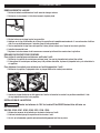
BATTERY PACK INSTALLATION
CAUTION
Only SENCO VB-Series 18V batteries should be used on SENCO tools:
VB-0155, 0160, 0161, 0162, 0190, 0191, 0194, 0195.
1. Align battery ribs with slots on the tool.
2. Push battery until it seats tightly on the tool.
3. A click can be heard when the release mechanism seats properly.

13
TOOL OPERATION
BATTERY PACK REMOVAL
1. Depress buttons on both sides of battery.
2. Slide battery off tool.
BATTERY CHARGING
1. Place battery pack in charger.
2. Align raised ribs on battery pack with groove in charger.
3. Press down on battery pack to be sure contacts on battery pack engage properly with contacts in
charger. When properly connected, the red light will turn on. Red flashing light indicates fast
charging mode.
4. Red and green light flashing indicates defective battery pack. Return battery pack to your nearest
SENCO Authorized Service Centre for inspection or replacement.
5. Solid red light indicates that the battery is charging.
6. When your battery pack becomes 80% charged, the red light will stay on and the green light will flash.
When battery pack is fully charged, the red light will turn off and the green light will turn on.
7. After normal usage, 1 hour of charge time is required to be fully charged. A maximum charge time of
1 hour or less is required to recharge a completely discharged battery pack.
8. The battery pack will become slightly warm to the touch while charging. This is normal and does not
indicate a problem.
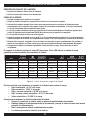
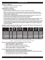
The battery pack houses 4 coloured LED lights. These LEDs indicate the state of charge and possible
problems inside the battery pack.
Standby/Power No Fade X X X X X
Standby Full Yes Fade Fade Ready for Use X X X
Charging Yes Solid Green Flashing Green <80% X X X
Fully Charged Yes Fading Green Fading Green 100% X X X
Evaluating Yes Solid Green X Measuring Flash Orange X X
*Temp Delay Yes Solid Green X Hot/Cold X Flash Orange X
Defective Yes Solid Green X Damaged X X Solid Red
Mode Power Charging/Full Condition Evaluate Temp. Delay Defective
Battery Pack
Inserted?
*Delay up to 20 minutes depending on battery cell temperature inside pack.
Figure 2 - Battery Charge Level Lights
Press raised red button on battery pack to check charge:
• Red Flashing = 0-15% Charge
• Red On = 16-25% Charge
• Red and Orange On = 26-50% Charge
• Red, Orange, and Green On = 51-75% Charge
• All On = 76-100% Charge
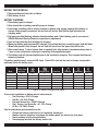
Tips for maintaining maximum battery life:
• Charge the battery pack before it is completely discharged.
• Always stop tool operation and charge the battery when you notice less tool power.
• Never recharge a fully charged battery.
• Overcharging shortens the battery service life.

14
Battery Disposal
• To preserve natural resources, please recycle or dispose of properly. This product contains
Li-Ion. Local state or federal laws may prohibit disposal of Li-Ion batteries in ordinary trash.
• Consult your local waste authority for information regarding available recycling and/or
disposal options.
• For more information on battery recycling call 1-800-8BATTERY.
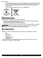
Maintenance
Read section titled “Safety Warnings” before maintaining tool.
1. With battery removed, make daily inspection to ensure free movement of nosepiece and trigger.
Do not use tool if nosepiece or trigger sticks or binds.
2. Lubrication of the feed system is not necessary. DO NOT OIL.
3. Wipe tool clean daily and inspect for wear, especially the bit and nosepiece. Replace as necessary.
WARNING
Repairs other than those described here should be performed only by trained,
qualified personnel. Contact SENCO for information at 1-800-543-4596.
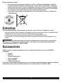
Accessories
SENCO offers a full line of DuraSpin screws and accessories for your SENCO tools, including:
• Bits
• Batteries
• Battery Chargers
• Storage Bag
• Assorted Nosepieces
• Safety Glasses
For more information or a fully illustrated catalogue of Senco accessories, contact your sales
representative or call Senco at 1-800-543-4596.

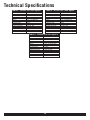
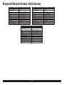
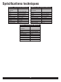
Technical Specifications
Table 4 - DS222-18V Tech Specs
VOLTAGE 18V
BATTERY AMPACITY 3000MAH
RPM 0-1600, 0-2500 REV/MIN
WEIGHT 5.47 LBS. (2.48KG) W/ BATTERY
HEIGHT 9.59" (243.5MM) MAX
LENGTH 14.66" (372.4MM) MAX
WIDTH 3.36" (85.4MM) MAX
RECHARGE TIME 1 HOUR
FASTENER CAPACITY 50 SCREWS (1 STRIP)
TORQUE DELIVERED 70 IN-LBS. MIN
GENERATED NOISE 84DB(A)
VIBRATION 2.5M/S2 MAX
FASTENER LENGTH 1-2"
FASTER RANGE #6-#12
Table 6 - DS322-18V Tech Specs
VOLTAGE 18V
BATTERY AMPACITY 3000MAH
RPM 0-1600, 0-2500 REV/MIN
WEIGHT 5.95 LBS. (2.70KG) MAX
HEIGHT 9.59” (243.5MM) MAX
LENGTH 16.52” (419.5MM) MAX
WIDTH 3.36” (85.4MM) MAX
RECHARGE TIME 1 HOUR
FASTENER CAPACITY 50 SCREWS (1 STRIP)
TORQUE DELIVERED 70 IN-LBS. MIN
GENERATED NOISE 84DB(A)
VIBRATION 2.5M/S2 MAX
FASTENER LENGTH 1-3”
FASTER RANGE #6-#12
Table 5 - DS225-18V Tech Specs
VOLTAGE 18V
BATTERY AMPACITY 3000MAH
RPM 0-5000 REV/MIN
WEIGHT 5.42 LBS. (2.46KG) MAX
HEIGHT 9.59” (243.5MM) MAX
LENGTH 14.66” (372.4MM) MAX
WIDTH 3.36” (85.4MM) MAX
RECHARGE TIME 1 HOUR
FASTENER CAPACITY 50 SCREWS (1 STRIP)
TORQUE DELIVERED 42 IN-LBS. MIN
GENERATED NOISE 84DB(A)
VIBRATION 2.5M/S2 MAX
FASTENER LENGTH 1-2”
FASTER RANGE #6-#12
15

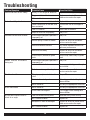
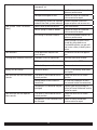
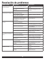
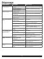
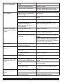
Troubleshooting
Problem/Symptom Probable Cause Corrective Action
Tool will not start or run slowly Battery is discharged or defective Replace with charged battery pack
Trigger switch is defective Replace or return to Senco autho-
rized service centre for repair
Motor is defective
Tool will not fully drive fastener Bit is worn or incorrect bit installed Replace bit
Power capabilities of the tool have
been exceeded
Discontinue use for that applica-
tion
Tool is in reverse Switch tool to forward
Depth of drive not set properly See p. #10
Tool does not advance fastener Screw length/nosepiece position is
improperly set
See p. #9
Return spring is weak or broken Replace or return to authorized
service centre for repair
Defective collation material Use Senco branded fasteners for
optimum performance
Defective slide body Replace or return to authorized
service centre for repair
Screw strip is jammed in guide
track
Ensure strip slides freely in guide
track
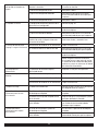
Screws “kick out” or misdrive
during use
Screw length/nosepiece position is
improperly set
See p. #9
Incorrect bit installed Ensure correct bit type and length
are installed
Defective or damaged feed system Return to Senco or Authorized
service centre for repair
Bit will not install Bit not properly inserted into drive
shaft
See p. #11
Clutch teeth not aligned Pulse trigger while holding back
release button
Not a Senco bit Use only the appropriate Senco bit
Bit will not release Not a Senco bit Use only the appropriate Senco bit
Clutch teeth not aligned Pulse trigger while holding back
release button
Bit slips off screw or screw is
driven at an angle
Tool slid forward during drive Hold tool firmly while driving
Bit is worn or broken Replace bit
Nosepiece is worn or damaged Replace or return to Senco autho-
rized service centre for repair
Bit is worn or broken Replace bit
16

17
Fastener Jams Screw length/nosepiece position is
improperly set
See p. #9
Defective collation material Use Senco branded fasteners for
optimum performance
Nosepiece damaged or bent Replace or return to authorized
service centre for repair
Screw partially driven into collation
material then feed system released
Remove jammed screw with
fingers or pliers and resume use
Feed system “sticks” or returns
slowly
Debris build-up on mechanism Clean mechanism
Return spring is weak or broken Replace or return to authorized
service centre for repair
Bit sticking in collation material Use Senco branded fasteners for
optimum performance
Always attempt to store screws
in cool dry place before use.
Overheated collation can get soft
and cause a delay in feed system
return
Tool overheats Drive application requires too
much torque
Discontinue use for that applica-
tion
Pushing force becomes excessive Improper screw for application Consider alternative fastener
CAM screw is loose or damaged Tighten or replace CAM screw
Debris build-up on mechanism Clean mechanism
Battery will not charge Defective battery See p. #12 for battery error code
description
Tool front-end will not install onto
console
The collar is not turned to the full
unlock position
Rotate the collar to full unlock
position
Foreign object stuck inside the
connection
Be sure that no objects or parts
are jammed inside the connection
Components in connector may be
damaged
Replace front-end assembly or
return to Senco Authorized service
centre for repair
Tool front-end will not separate
from console
The collar is not turned to the full
unlock position
Rotate the collar to full unlock
position
Components in the connector may
be damaged
Return to Senco Authorized
service centre for repair

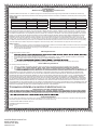
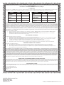
Limited Warranty
SENCO
®
Pneumatic, DuraSpin
®
, Cordless Tools
& Compressors
KYOCERA-SENCO Industrial Tools, Inc. (“SENCO”) designs and constructs its products using the highest standards of material and workmanship.
SENCO warrants to the original retail purchaser that the following products will be free from defects in material or workmanship for the warranty period
Products New Reconditioned Products New Reconditioned
Pneumatic Tools
Ü
Five Years One Year Air Compressors One Year 90 Days
Fusion Tools Two Years Six Months Combo Kit Tools One Year 90 Days
Gas Tools Two Years Six Months Multi-Blow Hand Nailers One Year 90 Days
Duraspin Tools One Year 90 Days Stapling Hammers One Year 90 Days
Ü
= Both XP and Pro Series
During the warranty period (which begins on the purchase date), SENCO will repair or replace, at SENCO’s option and expense, any product or part
that is defective in materials or workmanship after examination by a SENCO Authorized Warranty Service Centre, subject to the exceptions, exclusions
and limitations described below. Any replacement product or part will carry a warranty for the balance of the warranty period applicable to the replaced
product or part. A DATED SALES RECEIPT OR PROOF OF PURCHASE FROM THE ORIGINAL RETAIL PURCHASER IS REQUIRED TO MAKE A
WARRANTY CLAIM. Warranty registration is also required and can be accomplished through on-line Product Registration at www.senco.com or by
completing and returning the postage paid warranty registration form included with your Operator’s manual/parts chart information, found inside the
product carton. To make a warranty claim, you must return the product, with proper receipt/proof of purchase and return transportation charges prepaid,
to a SENCO Authorized Warranty Service Centre. A list of SENCO Authorized Warranty Service Centres can be found at www.senco.com or by calling
1-800-543-4596 toll free. SENCO will perform its obligations under this warranty within a reasonable time after approval of the warranty claim.
SENCO Cordless:
1. Subject to the exceptions, exclusions and limitations described below, SENCO warrants that the SENCO Cordless tool will be free from defects
in materials and workmanship for two years after the purchase date.
2. SENCO warrants that the batteries and chargers used with SENCO Cordless tools will be free from defects in material and workmanship for
one year after the purchase date.
Warranty Exclusions
The following warranty exclusions apply:
1.
seals, driver blades, piston stops, and piston/driver assembly.
2. This warranty does not cover parts damaged due to normal wear, misapplication, misuse, accidents, operation beyond the recommended
speeds or voltage (electric units only), improper storage, or damage resulting from shipping.
3. Prod
4. Labour charges or loss or damage resulting from improper operation, maintenance or repairs are not covered by this warranty.
General Warranty Conditions
This warranty will be honoured only if:
A. Clean, dry, regulated compressed air has been used, at air pressure not exceeding the maximum indicated on the tool casting;
B. No e
C. No d
maintenance instructions).
THIS WARRANTY IS THE ONLY WARRANTY ON THE PRODUCT, AND SENCO DISCLAIMS ALL OTHER WARRANTIES. ANY IMPLIED WAR-
RANTIES WILL BE LIMITED IN DURATION TO THE APPLICABLE WARRANTY PERIOD SPECIFIED ABOVE. SOME STATES DO NOT ALLOW
LIMITATIONS ON HOW LONG AN IMPLIED WARRANTY LASTS, SO THE ABOVE LIMITATION MAY NOT APPLY TO YOU. YOUR REMEDIES ARE
SOLELY AND EXCLUSIVELY AS STATED ABOVE. SENCO SHALL IN NO EVENT BE LIABLE FOR INCIDENTAL, CONSEQUENTIAL, INDIRECT,
OR SPECIAL DAMAGES. SOME STATES DO NOT ALLOW THE EXCLUSION OR LIMITATION OF INCIDENTAL OR CONSEQUENTIAL DAMAGES,
SO THE ABOVE LIMITATION OR EXCLUSION MAY NOT APPLY TO YOU. IN NO EVENT, WHETHER AS A RESULT OF A BREACH OF CONTRACT,
WARRANTY, TORT (INCLUDING NEGLIGENCE) OR OTHERWISE, SHALL SENCO’S LIABILITY EXCEED THE PRICE OF THE PRODUCT WHICH
HAS GIVEN RISE TO THE CLAIM OR LIABILITY. ANY LIABILITY CONNECTED WITH THE USE OF THIS PRODUCT SHALL TERMINATE UPON THE
EXPIRATION OF THE WARRANTY PERIOD SPECIFIED ABOVE. NO EMPLOYEE OR REPRESENTATIVE OF SENCO OR ANY DISTRIBUTOR OR
DEALER IS AUTHORIZED TO MAKE ANY CHANGE OR MODIFICATION TO THIS WARRANTY.
Replacement of Tool Due to Natural Disaster
Such a claim will be honoured provided that the original retail purchaser had previously submitted a completed warranty registration card for the tool,
and then submits proof of ownership and an acceptable statement describing such Act of God documented by an insurance carrier, police department,
Customer Satisfaction
If for any reason the product does not perform to the original purchaser’s satisfaction, it can be returned to the place of purchase within thirty days with
dated sales receipt for a full refund of the purchase price (applies to new product sales only).
© 2019 KYOCERA-SENCO Industrial Tools, Inc.
CINCINNATI, OHIO 45244-1611 USA
www.senco.com
160101
KYOCERA SENCO Industrial Tools
8450 Broadwell Road
Cincinnati, Ohio 45244
www.senco.com
© 2019 by KYOCERA-SENCO Industrial Tools, Inc.

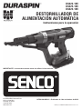
DS222-18V
DS225-18V
DS322-18V
DESTORNILLADOR DE
ALIMENTACIÓN AUTOMÁTICA
Instrucciones para la operación
KYOCERA SENCO Industrial Tools
4270 Ivy Pointe Blvd.
Cincinnati, OH 45245
1-800-543-4596
www.senco.com
© 2019 por KYOCERA-SENCO Industrial Tools, Inc.
NFD810A10B10C • Publicado el 4 de noviembre de 2019
IMPORTANTE: Lea este documento antes de utilizar la herramienta.

Índice
Símbolos .................................................................................................................................. 3
Advertencias generales de seguridad con las herramientas eléctricas ................................ 4
Seguridad en el área de trabajo ............................................................................................. 4
Seguridad con la electricidad ................................................................................................ 4
Seguridad personal ............................................................................................................... 4
Uso y cuidado de las herramientas eléctricas ....................................................................... 5
Uso y cuidado de las herramientas de baterías ..................................................................... 5
Servicio ................................................................................................................................. 6
Advertencias de seguridad del destornillador ........................................................................ 6
Advertencias de seguridad en cuanto al cargador y la batería .............................................. 6
Descripción funcional .............................................................................................................. 8
Operación de la herramienta .................................................................................................. 9
Ajuste de la longitud del sujetador ........................................................................................ 9
Carga de la herramienta ........................................................................................................ 9
Ajuste de la velocidad a la que se introducen los tornillos .................................................. 10
Inserción de los tornillos ..................................................................................................... 10
Seguro del disparador ......................................................................................................... 10
Ajuste de la profundidad a la que se introducen los tornillos .............................................. 10
Operación inversa ............................................................................................................... 11
Reemplazo de la broca ........................................................................................................ 11
Reemplazo de la punta ........................................................................................................ 12
Ajuste del gancho de cinturón ............................................................................................. 12
Instalación del paquete de la batería ................................................................................... 12
Remoción del paquete de la batería .................................................................................... 13
Carga de la batería .............................................................................................................. 13
Eliminación de la batería ..................................................................................................... 14
Mantenimiento ...................................................................................................................... 14
Accesorios ............................................................................................................................. 14
Especificaciones técnicas ..................................................................................................... 15
Solución de problemas ......................................................................................................... 16
2
La page est en cours de chargement...
La page est en cours de chargement...
La page est en cours de chargement...
La page est en cours de chargement...
La page est en cours de chargement...
La page est en cours de chargement...
La page est en cours de chargement...
La page est en cours de chargement...
La page est en cours de chargement...
La page est en cours de chargement...
La page est en cours de chargement...
La page est en cours de chargement...
La page est en cours de chargement...
La page est en cours de chargement...
La page est en cours de chargement...
La page est en cours de chargement...
La page est en cours de chargement...
La page est en cours de chargement...
La page est en cours de chargement...
La page est en cours de chargement...
La page est en cours de chargement...
La page est en cours de chargement...
La page est en cours de chargement...
La page est en cours de chargement...
La page est en cours de chargement...
La page est en cours de chargement...
La page est en cours de chargement...
La page est en cours de chargement...
La page est en cours de chargement...
La page est en cours de chargement...
La page est en cours de chargement...
La page est en cours de chargement...
La page est en cours de chargement...
La page est en cours de chargement...
-
 1
1
-
 2
2
-
 3
3
-
 4
4
-
 5
5
-
 6
6
-
 7
7
-
 8
8
-
 9
9
-
 10
10
-
 11
11
-
 12
12
-
 13
13
-
 14
14
-
 15
15
-
 16
16
-
 17
17
-
 18
18
-
 19
19
-
 20
20
-
 21
21
-
 22
22
-
 23
23
-
 24
24
-
 25
25
-
 26
26
-
 27
27
-
 28
28
-
 29
29
-
 30
30
-
 31
31
-
 32
32
-
 33
33
-
 34
34
-
 35
35
-
 36
36
-
 37
37
-
 38
38
-
 39
39
-
 40
40
-
 41
41
-
 42
42
-
 43
43
-
 44
44
-
 45
45
-
 46
46
-
 47
47
-
 48
48
-
 49
49
-
 50
50
-
 51
51
-
 52
52
-
 53
53
-
 54
54


Senco 10B0001N Le manuel du propriétaire
- Catégorie
- Outils électroportatifs
- Taper
- Le manuel du propriétaire
dans d''autres langues
Documents connexes
-
Senco DS312-18V Le manuel du propriétaire
-
Senco DS342-AC Le manuel du propriétaire
-
-
-
-
-
-
Senco 7Y0001N Information produit
-
-
Senco PC1010 Guide d'installation