Lincoln Electric LN-742 Mode d'emploi
- Catégorie
- Système de soudage
- Taper
- Mode d'emploi
Ce manuel convient également à

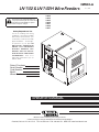
LN-742 & LN-742H Wire Feeders
OPERATOR’S MANUAL
IM502-A
June, 2000
Safety Depends on You
Lincoln arc welding and cutting
equipment is designed and built
with safety in mind. However, your
overall safety can be increased by
proper installation ... and thought-
ful operation on your part.
DO
NOT INSTALL, OPERATE OR
REPAIR THIS EQUIPMENT
WITHOUT READING THIS
MANUAL AND THE SAFETY
PRECAUTIONS CONTAINED
THROUGHOUT.
And, most
importantly, think before you act
and be careful.
For use with machines having Code Numbers:
10029
10030
10234
10235
10236
10237
10046
10047
• Sales and Service through Subsidiaries and Distributors Worldwide •
Cleveland, Ohio 44117-1199 U.S.A. TEL: 216.481.8100 FAX: 216.486.1751 WEB SITE: www.lincolnelectric.com
• World's Leader in Welding and Cutting Products •
Date of Purchase:
Serial Number:
Code Number:
Model:
Where Purchased:
This manual covers equipment which is no
longer in production by The Lincoln Electric Co.
Specications and availability of optional
features may have changed.

FOR ENGINE
powered equipment.
1.a. Turn the engine off before troubleshooting and maintenance
work unless the maintenance work requires it to be running.
____________________________________________________
1.b.Operate engines in open, well-ventilated
areas or vent the engine exhaust fumes
outdoors.
____________________________________________________
1.c. Do not add the fuel near an open flame
welding arc or when the engine is running.
Stop the engine and allow it to cool before
refueling to prevent spilled fuel from vaporiz-
ing on contact with hot engine parts and
igniting. Do not spill fuel when filling tank. If
fuel is spilled, wipe it up and do not start
engine until fumes have been eliminated.
____________________________________________________
1.d. Keep all equipment safety guards, covers
and devices in position and in good
repair.Keep hands, hair, clothing and tools
away from V-belts, gears, fans and all other
moving parts when starting, operating or
repairing equipment.
____________________________________________________
1.e. In some cases it may be necessary to remove safety
guards to perform required maintenance. Remove
guards only when necessary and replace them when the
maintenance requiring their removal is complete.
Always use the greatest care when working near moving
parts.
___________________________________________________
1.f. Do not put your hands near the engine fan. Do not attempt
to override the governor or idler by pushing on the throttle
control rods while the engine is running.
___________________________________________________
1.g. To prevent accidentally starting gasoline engines while
turning the engine or welding generator during maintenance
work, disconnect the spark plug wires, distributor cap or
magneto wire as appropriate.
i
SAFETY
i
ARC WELDING CAN BE HAZARDOUS. PROTECT YOURSELF AND OTHERS FROM POSSIBLE SERIOUS INJURY OR DEATH.
KEEP CHILDREN AWAY. PACEMAKER WEARERS SHOULD CONSULT WITH THEIR DOCTOR BEFORE OPERATING.
Read and understand the following safety highlights. For additional safety information, it is strongly recommended that you
purchase a copy of “Safety in Welding & Cutting - ANSI Standard Z49.1” from the American Welding Society, P.O. Box
351040, Miami, Florida 33135 or CSA Standard W117.2-1974. A Free copy of “Arc Welding Safety” booklet E205 is available
from the Lincoln Electric Company, 22801 St. Clair Avenue, Cleveland, Ohio 44117-1199.
BE SURE THAT ALL INSTALLATION, OPERATION, MAINTENANCE AND REPAIR PROCEDURES ARE
PERFORMED ONLY BY QUALIFIED INDIVIDUALS.
WARNING
Mar ‘95
ELECTRIC AND
MAGNETIC FIELDS
may be dangerous
2.a. Electric current flowing through any conductor causes
localized Electric and Magnetic Fields (EMF). Welding
current creates EMF fields around welding cables and
welding machines
2.b. EMF fields may interfere with some pacemakers, and
welders having a pacemaker should consult their physician
before welding.
2.c. Exposure to EMF fields in welding may have other health
effects which are now not known.
2.d. All welders should use the following procedures in order to
minimize exposure to EMF fields from the welding circuit:
2.d.1.
Route the electrode and work cables together - Secure
them with tape when possible.
2.d.2. Never coil the electrode lead around your body.
2.d.3. Do not place your body between the electrode and
work cables. If the electrode cable is on your right
side, the work cable should also be on your right side.
2.d.4. Connect the work cable to the workpiece as close as
possible to the area being welded.
2.d.5. Do not work next to welding power source.
1.h. To avoid scalding, do not remove the
radiator pressure cap when the engine is
hot.
CALIFORNIA PROPOSITION 65 WARNINGS
Diesel engine exhaust and some of its constituents
are known to the State of California to cause can-
cer, birth defects, and other reproductive harm.
The engine exhaust from this product contains
chemicals known to the State of California to cause
cancer, birth defects, or other reproductive harm.
The Above For Diesel Engines
The Above For Gasoline Engines

ii
SAFETY
ii
ARC RAYS can burn.
4.a. Use a shield with the proper filter and cover
plates to protect your eyes from sparks and
the rays of the arc when welding or observing
open arc welding. Headshield and filter lens
should conform to ANSI Z87. I standards.
4.b. Use suitable clothing made from durable flame-resistant
material to protect your skin and that of your helpers from
the arc rays.
4.c. Protect other nearby personnel with suitable, non-flammable
screening and/or warn them not to watch the arc nor expose
themselves to the arc rays or to hot spatter or metal.
ELECTRIC SHOCK can
kill.
3.a. The electrode and work (or ground) circuits
are electrically “hot” when the welder is on.
Do not touch these “hot” parts with your bare
skin or wet clothing. Wear dry, hole-free
gloves to insulate hands.
3.b. Insulate yourself from work and ground using dry insulation.
Make certain the insulation is large enough to cover your full
area of physical contact with work and ground.
In addition to the normal safety precautions, if welding
must be performed under electrically hazardous
conditions (in damp locations or while wearing wet
clothing; on metal structures such as floors, gratings or
scaffolds; when in cramped positions such as sitting,
kneeling or lying, if there is a high risk of unavoidable or
accidental contact with the workpiece or ground) use
the following equipment:
• Semiautomatic DC Constant Voltage (Wire) Welder.
• DC Manual (Stick) Welder.
• AC Welder with Reduced Voltage Control.
3.c. In semiautomatic or automatic wire welding, the electrode,
electrode reel, welding head, nozzle or semiautomatic
welding gun are also electrically “hot”.
3.d. Always be sure the work cable makes a good electrical
connection with the metal being welded. The connection
should be as close as possible to the area being welded.
3.e. Ground the work or metal to be welded to a good electrical
(earth) ground.
3.f.
Maintain the electrode holder, work clamp, welding cable and
welding machine in good, safe operating condition. Replace
damaged insulation.
3.g. Never dip the electrode in water for cooling.
3.h. Never simultaneously touch electrically “hot” parts of
electrode holders connected to two welders because voltage
between the two can be the total of the open circuit voltage
of both welders.
3.i. When working above floor level, use a safety belt to protect
yourself from a fall should you get a shock.
3.j. Also see Items 6.c. and 8.
FUMES AND GASES
can be dangerous.
5.a.Welding may produce fumes and gases
hazardous to health. Avoid breathing these
fumes and gases.When welding, keep
your head out of the fume. Use enough
ventilation and/or exhaust at the arc to keep
fumes and gases away from the breathing zone. When
welding with electrodes which require special
ventilation such as stainless or hard facing (see
instructions on container or MSDS) or on lead or
cadmium plated steel and other metals or coatings
which produce highly toxic fumes, keep exposure as
low as possible and below Threshold Limit Values (TLV)
using local exhaust or mechanical ventilation. In
confined spaces or in some circumstances, outdoors, a
respirator may be required. Additional precautions are
also required when welding on galvanized steel.
5.b.
Do not weld in locations near chlorinated hydrocarbon
vapors
coming from degreasing, cleaning or spraying operations.
The heat and rays of the arc can react with solvent vapors
to
form phosgene, a highly toxic gas, and other irritating
products.
5.c. Shielding gases used for arc welding can displace air and
cause injury or death. Always use enough ventilation,
especially in confined areas, to insure breathing air is safe.
5.d. Read and understand the manufacturer’s instructions for this
equipment and the consumables to be used, including the
material safety data sheet (MSDS) and follow your
employer’s safety practices. MSDS forms are available from
your welding distributor or from the manufacturer.
5.e. Also see item 1.b.
Mar ‘95

FOR ELECTRICALLY
powered equipment.
8.a. Turn off input power using the disconnect
switch at the fuse box before working on
the equipment.
8.b. Install equipment in accordance with the U.S. National
Electrical Code, all local codes and the manufacturer’s
recommendations.
8.c. Ground the equipment in accordance with the U.S. National
Electrical Code and the manufacturer’s recommendations.
CYLINDER may explode
if damaged.
7.a. Use only compressed gas cylinders
containing the correct shielding gas for the
process used and properly operating
regulators designed for the gas and
pressure used. All hoses, fittings, etc. should be suitable for
the application and maintained in good condition.
7.b. Always keep cylinders in an upright position securely
chained to an undercarriage or fixed support.
7.c. Cylinders should be located:
• Away from areas where they may be struck or subjected to
physical damage.
• A safe distance from arc welding or cutting operations and
any other source of heat, sparks, or flame.
7.d. Never allow the electrode, electrode holder or any other
electrically “hot” parts to touch a cylinder.
7.e. Keep your head and face away from the cylinder valve outlet
when opening the cylinder valve.
7.f. Valve protection caps should always be in place and hand
tight except when the cylinder is in use or connected for
use.
7.g. Read and follow the instructions on compressed gas
cylinders, associated equipment, and CGA publication P-l,
“Precautions for Safe Handling of Compressed Gases in
Cylinders,” available from the Compressed Gas Association
1235 Jefferson Davis Highway, Arlington, VA 22202.
iii
SAFETY
iii
Mar ‘95
WELDING SPARKS can
cause fire or explosion.
6.a.
Remove fire hazards from the welding area.
If this is not possible, cover them to prevent
the welding sparks from starting a fire.
Remember that welding sparks and hot
materials from welding can easily go through small cracks
and openings to adjacent areas. Avoid welding near
hydraulic lines. Have a fire extinguisher readily available.
6.b. Where compressed gases are to be used at the job site,
special precautions should be used to prevent hazardous
situations. Refer to “Safety in Welding and Cutting” (ANSI
Standard Z49.1) and the operating information for the
equipment being used.
6.c. When not welding, make certain no part of the electrode
circuit is touching the work or ground. Accidental contact
can cause overheating and create a fire hazard.
6.d. Do not heat, cut or weld tanks, drums or containers until the
proper steps have been taken to insure that such procedures
will not cause flammable or toxic vapors from substances
inside. They can cause an explosion even
though
they have
been “cleaned”. For information, purchase “Recommended
Safe Practices for the
Preparation
for Welding and Cutting of
Containers and Piping That Have Held Hazardous
Substances”, AWS F4.1 from the American Welding Society
(see address above).
6.e. Vent hollow castings or containers before heating, cutting or
welding. They may explode.
6.f.
Sparks and spatter are thrown from the welding arc. Wear oil
free protective garments such as leather gloves, heavy shirt,
cuffless trousers, high shoes and a cap over your hair. Wear
ear plugs when welding out of position or in confined places.
Always wear safety glasses with side shields when in a
welding area.
6.g. Connect the work cable to the work as close to the welding
area as practical. Work cables connected to the building
framework or other locations away from the welding area
increase the possibility of the welding current passing
through lifting chains, crane cables or other alternate cir-
cuits. This can create fire hazards or overheat lifting chains
or cables until they fail.
6.h. Also see item 1.c.

iv
SAFETY
iv
PRÉCAUTIONS DE SÛRETÉ
Pour votre propre protection lire et observer toutes les instructions
et les précautions de sûreté specifiques qui parraissent dans ce
manuel aussi bien que les précautions de sûreté générales suiv-
antes:
Sûreté Pour Soudage A L’Arc
1. Protegez-vous contre la secousse électrique:
a. Les circuits à l’électrode et à la piéce sont sous tension
quand la machine à souder est en marche. Eviter toujours
tout contact entre les parties sous tension et la peau nue
ou les vétements mouillés. Porter des gants secs et sans
trous pour isoler les mains.
b. Faire trés attention de bien s’isoler de la masse quand on
soude dans des endroits humides, ou sur un plancher
metallique ou des grilles metalliques, principalement dans
les positions assis ou couché pour lesquelles une grande
partie du corps peut être en contact avec la masse.
c. Maintenir le porte-électrode, la pince de masse, le câble
de soudage et la machine à souder en bon et sûr état
defonctionnement.
d.Ne jamais plonger le porte-électrode dans l’eau pour le
refroidir.
e. Ne jamais toucher simultanément les parties sous tension
des porte-électrodes connectés à deux machines à souder
parce que la tension entre les deux pinces peut être le
total de la tension à vide des deux machines.
f. Si on utilise la machine à souder comme une source de
courant pour soudage semi-automatique, ces precautions
pour le porte-électrode s’applicuent aussi au pistolet de
soudage.
2. Dans le cas de travail au dessus du niveau du sol, se protéger
contre les chutes dans le cas ou on recoit un choc. Ne jamais
enrouler le câble-électrode autour de n’importe quelle partie
du corps.
3. Un coup d’arc peut être plus sévère qu’un coup de soliel,
donc:
a. Utiliser un bon masque avec un verre filtrant approprié
ainsi qu’un verre blanc afin de se protéger les yeux du ray-
onnement de l’arc et des projections quand on soude ou
quand on regarde l’arc.
b. Porter des vêtements convenables afin de protéger la
peau de soudeur et des aides contre le rayonnement de
l‘arc.
c. Protéger l’autre personnel travaillant à proximité au
soudage à l’aide d’écrans appropriés et non-inflammables.
4. Des gouttes de laitier en fusion sont émises de l’arc de
soudage. Se protéger avec des vêtements de protection libres
de l’huile, tels que les gants en cuir, chemise épaisse, pan-
talons sans revers, et chaussures montantes.
5. Toujours porter des lunettes de sécurité dans la zone de
soudage. Utiliser des lunettes avec écrans lateraux dans les
zones où l’on pique le laitier.
6. Eloigner les matériaux inflammables ou les recouvrir afin de
prévenir tout risque d’incendie dû aux étincelles.
7. Quand on ne soude pas, poser la pince à une endroit isolé de
la masse. Un court-circuit accidental peut provoquer un
échauffement et un risque d’incendie.
8. S’assurer que la masse est connectée le plus prés possible
de la zone de travail qu’il est pratique de le faire. Si on place
la masse sur la charpente de la construction ou d’autres
endroits éloignés de la zone de travail, on augmente le risque
de voir passer le courant de soudage par les chaines de lev-
age, câbles de grue, ou autres circuits. Cela peut provoquer
des risques d’incendie ou d’echauffement des chaines et des
câbles jusqu’à ce qu’ils se rompent.
9. Assurer une ventilation suffisante dans la zone de soudage.
Ceci est particuliérement important pour le soudage de tôles
galvanisées plombées, ou cadmiées ou tout autre métal qui
produit des fumeés toxiques.
10. Ne pas souder en présence de vapeurs de chlore provenant
d’opérations de dégraissage, nettoyage ou pistolage. La
chaleur ou les rayons de l’arc peuvent réagir avec les vapeurs
du solvant pour produire du phosgéne (gas fortement toxique)
ou autres produits irritants.
11. Pour obtenir de plus amples renseignements sur la sûreté,
voir le code “Code for safety in welding and cutting” CSA
Standard W 117.2-1974.
PRÉCAUTIONS DE SÛRETÉ POUR
LES MACHINES À SOUDER À
TRANSFORMATEUR ET À
REDRESSEUR
1. Relier à la terre le chassis du poste conformement au code de
l’électricité et aux recommendations du fabricant. Le dispositif
de montage ou la piece à souder doit être branchéà une
bonne mise à la terre.
2. Autant que possible, I’installation et l’entretien du poste seront
effectués par un électricien qualifié.
3. Avant de faires des travaux à l’interieur de poste, la debranch-
er à l’interrupteur à la boite de fusibles.
4. Garder tous les couvercles et dispositifs de sûretéà leur
place.
Mar. ‘93

Thank You
for selecting a QUALITY product by Lincoln Electric. We want you
to take pride in operating this Lincoln Electric Company product
••• as much pride as we have in bringing this product to you!
Read this Operators Manual completely before attempting to use this equipment. Save this manual and keep it
handy for quick reference. Pay particular attention to the safety instructions we have provided for your protection.
The level of seriousness to be applied to each is explained below:
WARNING
This statement appears where the information must be followed exactly to avoid serious personal injury or
loss of life.
This statement appears where the information must be followed to avoid minor personal injury or damage to
this equipment.
CAUTION
Please Examine Carton and Equipment For Damage Immediately
When this equipment is shipped, title passes to the purchaser upon receipt by the carrier. Consequently, Claims
for material damaged in shipment must be made by the purchaser against the transportation company at the
time the shipment is received.
Please record your equipment identification information below for future reference. This information can be
found on your machine nameplate.
Model Name & Number _____________________________________
Code & Serial Number _____________________________________
Date of Purchase _____________________________________
Whenever you request replacement parts for or information on this equipment always supply the information
you have recorded above.
vv

vi
TABLE OF CONTENTS
LN-742 & LN-742H
Page
Safety . . . . . . . . . . . . . . . . . . . . . . . . . . . . . . . . . . . . . . . . . . . . . . . . . . . . . . . i-iv
Installation . . . . . . . . . . . . . . . . . . . . . . . . . . . . . . . . . . . . . . . . . . . . . . . . . . . Section A
Technical Specifications - LN-742 . . . . . . . . . . . . . . . . . . . . . . . . . . . . . . A-1
Mounting Location . . . . . . . . . . . . . . . . . . . . . . . . . . . . . . . . . . . . . . . . . . A-2
Input Cable Connections . . . . . . . . . . . . . . . . . . . . . . . . . . . . . . . . . . . . . A-2
Work Cable . . . . . . . . . . . . . . . . . . . . . . . . . . . . . . . . . . . . . . . . . . . . . . . . A-5
Gun and Cable Assemblies . . . . . . . . . . . . . . . . . . . . . . . . . . . . . . . . . . . A-5
Gun Cable Connections . . . . . . . . . . . . . . . . . . . . . . . . . . . . . . . . . . . . . . A-5
Water Connections (For Water Cooled Guns) . . . . . . . . . . . . . . . . . . . . . A-6
GMAW Shielding Gas Hookup . . . . . . . . . . . . . . . . . . . . . . . . . . . . . . . . . A-7
Operation . . . . . . . . . . . . . . . . . . . . . . . . . . . . . . . . . . . . . . . . . . . . . . . . . . . . Section B
Operating Instructions . . . . . . . . . . . . . . . . . . . . . . . . . . . . . . . . . . . . . . . B-1
Safety Precautions . . . . . . . . . . . . . . . . . . . . . . . . . . . . . . . . . . . . . . . . . . B-1
General Description . . . . . . . . . . . . . . . . . . . . . . . . . . . . . . . . . . . . . . . . . B-1
Recommended Processes and Equipment . . . . . . . . . . . . . . . . . . . . . . . B-1
Controls and Settings . . . . . . . . . . . . . . . . . . . . . . . . . . . . . . . . . . . . . . . . B-2
Acceleration Setting . . . . . . . . . . . . . . . . . . . . . . . . . . . . . . . . . . . . . . . . . B-3
English or Metric Speed Display Units . . . . . . . . . . . . . . . . . . . . . . . . . . . B-3
Circuit Protection . . . . . . . . . . . . . . . . . . . . . . . . . . . . . . . . . . . . . . . . . . . B-3
Drive Roll Installation . . . . . . . . . . . . . . . . . . . . . . . . . . . . . . . . . . . . . . . . B-3
Idle Roll Pressure Setting . . . . . . . . . . . . . . . . . . . . . . . . . . . . . . . . . . . . . B-7
Wire Loading . . . . . . . . . . . . . . . . . . . . . . . . . . . . . . . . . . . . . . . . . . . . . . B-8
Making a Weld . . . . . . . . . . . . . . . . . . . . . . . . . . . . . . . . . . . . . . . . . . . . . B-12
Wire Reel Changing . . . . . . . . . . . . . . . . . . . . . . . . . . . . . . . . . . . . . . . . . B-12
Accessories . . . . . . . . . . . . . . . . . . . . . . . . . . . . . . . . . . . . . . . . . . . . . . . . . . Section C
General . . . . . . . . . . . . . . . . . . . . . . . . . . . . . . . . . . . . . . . . . . . . . . . . . . . C-1
Flux System Components . . . . . . . . . . . . . . . . . . . . . . . . . . . . . . . . . . . . C-2
Power Input Cables . . . . . . . . . . . . . . . . . . . . . . . . . . . . . . . . . . . . . . . . . C-3
Welding Guns . . . . . . . . . . . . . . . . . . . . . . . . . . . . . . . . . . . . . . . . . . . . . . C-3
Spindles, Stands, and Adapters . . . . . . . . . . . . . . . . . . . . . . . . . . . . . . . . C-4
Attaching the Wire Reel Stand . . . . . . . . . . . . . . . . . . . . . . . . . . . . . . . . . C-5
Drive Roll Kits . . . . . . . . . . . . . . . . . . . . . . . . . . . . . . . . . . . . . . . . . . . . . . C-6
Maintenance . . . . . . . . . . . . . . . . . . . . . . . . . . . . . . . . . . . . . . . . . . . . . . . . . Section D
Routine Maintenance . . . . . . . . . . . . . . . . . . . . . . . . . . . . . . . . . . . . . . . . D-1
Periodic Maintenance . . . . . . . . . . . . . . . . . . . . . . . . . . . . . . . . . . . . . . . . D-1
Troubleshooting and Repair . . . . . . . . . . . . . . . . . . . . . . . . . . . . . . . . . . . . Section E
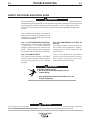
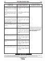
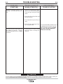
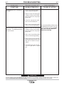
How To Use Troubleshooting Guide . . . . . . . . . . . . . . . . . . . . . . . . . . . . E-1
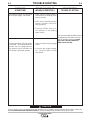
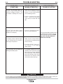
Troubleshooting Guide . . . . . . . . . . . . . . . . . . . . . . . . . . . . . . . . . . . . . . . E-2
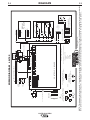
Electrical Diagram . . . . . . . . . . . . . . . . . . . . . . . . . . . . . . . . . . . . . . . . . . . . . Section F
Parts Manual . . . . . . . . . . . . . . . . . . . . . . . . . . . . . . . . . . . . . . . . . . . . . . . . . Appendix

A-1
INSTALLATION
A-1
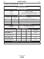
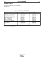
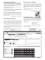
PHYSICAL DIMENSIONS
ENVIRONMENTAL RATING (ALL MODELS)
BOTH LN-742 AND LN-742H
LENGTH
TOTAL WEIGHT
LESS ELECTRODE
24.3 lbs
(11.1 kg)
WIDTH
HEIGHT
2 ROLL FEEDER
WITH WIRE STAND (K377)
2 ROLL FEEDER
WITHOUT WIRE STAND
4 ROLL FEEDER
WITH WIRE STAND (K377)
4 ROLL FEEDER
WITHOUT WIRE STAND
34.3 lbs
(15.6 kg)
29.0 lbs
(13.2 kg)
39.0 lbs
(17.8 kg)
10.52 in.
(267 mm)
21.58 in.
(548 mm)
11.50 in.
(292 mm)
22.56 in.
(573 mm)
9.76 in.
(247 mm)
9.76 in.
(247 mm)
11.60 in.
(295 mm)
11.60 in.
(295 mm)
10.89 in.
(277 mm)
17.00 in.
(432 mm)
11.11 in.
(282 mm)
17.00 in.
(432 mm)
SYSTEM
LN-742
LN-742H
DIAMETER
0.025 in. through 1/16 in. (0.6 through 1.6 mm)
0.025 in. through 0.045 in. (0.6 through 1.2 mm)
0.045 in. through 3/32 in. (1.2 through 2.4 mm)
0.045 in. (1.2 mm)
TECHNICAL SPECIFICATIONS – LN-742
INPUT VOLTAGE
WIRE FEED SPEED
WIRE DIAMETERS
40 to 42V ±10%, 50/60 Hz, 4.0 Amps
WIRE SPEED RANGE
50 in. to 770 in. per minute (1.25 to 19.5 m/min)
80 in. to 1200 in. per minute (2.00 to 30.5 m/min)
SYSTEM
LN-742
LN-742H
LN-742
LN-742H
ELECTRODE
SOLID
SOLID
CORED
CORED
TEMPERATURE RATING (ALL MODELS)
OPERATING
STORAGE
-4˚F to 104˚F (-20˚C to +40˚C)
-40˚F to 104˚F (-40˚C to +40˚C)
LN-742 & LN-742H
IP21 (IEC 974-5)

A-2
INSTALLATION
LN-742 & LN-742H
A-2
MOUNTING LOCATION
The LN-742 wire feeders can be mounted directly on
top of the power source providing that it is secure and
level. The LN-742 can also be mounted to an
undercarriage when portability is required. The LN-742
should be installed upright on a horizontal surface.
A K178-1 mounting platform is available for mounting
the LN-742 to the top of Idealarc power sources. Refer
to Section C, Accessories, for details.
INPUT CABLE CONNECTIONS
Refer to Section C, Accessories, for descriptions of
the various input cable assemblies available for the
LN-742 wire feeder.
Turn input power off before connecting the LN-742
wire feeder.
------------------------------------------------------------------------
For connecting an LN-742 to a specific Lincoln power
source, follow steps 1 through 5, and refer to the
connection diagram in Figure A.3. The welding cable
used must be sized according to the current and the
duty cycle of the application.
With input power disconnected at the source, install
the input cable per connection diagram A.3, and
complete the following instructions:
1. Connect the end of the control cable with the 14-
pin cable plug to the mating receptacle on the
power source.
2. Connect the electrode lead to the power source
output terminal of the desired polarity.
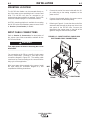
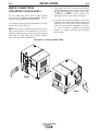
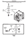
3. Referring to Figure A.1, route the other end of the
electrode cable through the large oval hole in the
rear panel of the LN-742 case. Connect the
electrode to the copper strap on the side of the
gearbox using the stud and nut provided.
FIGURE A.1 – INPUT CONTROL CABLE AND
ELECTRODE CABLE CONNECTIONS.
WARNING
NUT
STUD
ELECTRODE
CONTROL
CABLE
COPPER
STRAP

A-3
INSTALLATION
LN-742 & LN-742H
A-3
4. Connect the remaining end of the control cable
with the eight-socket cable plug to the mating
receptacle on the LN-742.
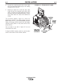
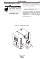
5. Referring to Figure A.2, install the input cable
under the wire reel mounting stand strain relief
clamp. Remove the screws holding the clamp to
the base of wire reel mounting assembly. Put the
input cable under the clamp and reinstall the
screws.
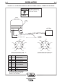
The connection diagram, Figure A.3, shows the
electrode as positive. To change polarity, turn the
power source off. Reverse the electrode and work
cables at the power source, and set the wire feeder
voltmeter polarity switch on the power source to the
proper polarity.
Pins not listed in the table in Figure A.3 are not
connected on the cable.
If using the K589-1 remote control kit, set the power
source control switch to the “Remote” position.
WIRE REEL
MOUNTING
ASSEMBLY
CONTROL
CABLE
ELECTRODE
CABLE
STRAIN
RELIEF
CLAMP
FIGURE A.2 – STRAIN RELIEF CLAMP.

A-4
INSTALLATION
LN-742 & LN-742H
A-4
ELECTRIC
SHOCK
CAN KILL
TURN INPUT POWER OFF
BEFORE CONNECTING THE
LN-742 WIRE FEEDER.
WARNING
CLEVELAND, OHIO U.S.A
-
+
LINCOLN
POWER SOURCE
LN-742
WIRE FEEDER
LN-742
INPUT CABLE
ASSEMBLY
TO WORK
ELECTRODE CABLE
14-SOCKET BOX RECEPTACLE, FRONT VIEW
AND 14-PIN CABLE PLUG, REAR VIEW
FUNCTIONS ARE LISTED FOR REFERENCE
ONLY AND EACH MAY OR MAY NOT BE
PRESENT IN YOUR EQUIPMENT.
14-SOCKET BOX RECEPTACLE, REAR VIEW
AND 14-PIN CABLE PLUG, FRONT VIEW
14 PIN
AMPHENOL
K=42
K=42
I=41 I=41
H=21 H=21C=2 C=2
G=75 G=75D=4 D=4
F=76
PIN
C
2 TRIGGER CIRCUIT
TRIGGER CIRCUIT
OUTPUT CONTROL
OUTPUT CONTROL
OUTPUT CONTROL
WORK
42V AC
42V AC
4
77
76
75
21
41
42
LEAD FUNCTION
F=76E=77 E=77
D
E
F
G
H
I
K
FIGURE A.3 – LN-742 WIRE FEEDER TO LINCOLN POWER SOURCE – CONNECTION DIAGRAM.

A-5
INSTALLATION
LN-742 & LN-742H
A-5
WORK CABLE
Connect a work lead of sufficient size and length
(Table A.1) between the proper output stud on the
power source and the work. Be sure the connection to
the work makes tight metal-to-metal electrical contact.
TABLE A.1 – WORK LEAD SPECIFICATIONS
Copper Work Cable Size, AWG
Current 60% Up To 50 Ft 50 Ft-100 Ft
Duty Cycle (15.2 m) (15.2-30.4 m)
300 Amps 0 (53 mm
2
) 00 (67 mm
2
)
400 Amps 00 (67 mm
2
) 000 (85 mm
2
)
500 Amps 00 (67 mm
2
) 000 (85 mm
2
)
600 Amps 000 (85 mm
2
) 0000 (107 mm
2
)
GUN AND CABLE ASSEMBLIES
An expanding line of Magnum Fast-Mate gun and
cable assemblies are available to allow welding with
solid and cored electrodes using the GMAW process.
See the appropriate Magnum literature for descriptions
of the 200 to 400 ampere air cooled gun and cables
that are available. Gun cable lengths range from 10 ft.
(3.0m) to 25 ft. (7.6m) and feed electrode sizes .025”
(0.6mm) to 5/64” (2.0mm).
An expanding line of Magnum X-Tractor gun and cable
assemblies provides fume extraction capability for
welding with solid and cored electrodes using the
GMAW process. See the appropriate Magnum
literature for descriptions of the 250 to 400 ampere air
cooled gun and cables that are available. Gun cable
lengths range from 10 ft. (3.0 m) to 15 ft. (4.5 m) and
feed electrode sizes .035” (0.9 mm) to 1/16” (1.6 mm).
These guns require the use of either the K173-1 or
K184* vacuum units.
* Requires S14927-8 connector hose and an S20591 hose adapter.

A-6
INSTALLATION
LN-742 & LN-742H
A-6
WATER CONNECTIONS
(FOR WATER COOLED GUNS)
The LN-7 GMA must have a K590-1 Water Solenoid
Kit installed (see Section C, Accessories). Refer to
Figure A.4 and perform the following steps:
The maximum water pressure permitted for use with
the LN-742 is 55 psi (3.8 bar).
NOTE: If not using a Lincoln water cooler, and if your
water cooling device is not designed for use with a
waterline solenoid valve, you may remove the solenoid
and screw the male fitting (after applying sealant)
directly into the brass manifold block.
1. Using male 5/8-18 UNF left-hand thread fittings,
connect appropriate water hoses to the coolant
inlet and outlet on the back of the LN-742.
Connect the other ends of these hoses to the
appropriate ports on your water cooling units.
2. In the event the water line fittings on your water
cooled gun are incompatible with the female quick
connects on the front of the LN-742, male quick
connects are provided for installation on 3/16 in.
I.D. hose (customer to provide appropriate
clamps). The feeder connectors self seal when
disconnected.
FIGURE A.4 – WATER CONNECTIONS.
t
t
FRONT
BACK

A-7
INSTALLATION
LN-742 & LN-742H
A-7
GMAW SHIELDING GAS HOOKUP
Gas under pressure is explosive.
Always keep gas cylinders in an
upright position and chained to the
undercarriage or a stationary
support. See American National
Standard Z-49.1, “Safety In Welding
And Cutting”, published by the
American Welding Society.
------------------------------------------------------------------------
Customer must provide a cylinder of shielding gas, a
pressure regulator, a flow control valve, and a hose
from the flow valve to the gas inlet fitting of the LN-742.
Install per Figure A.5 and the following:
1. Connect the supply hose from the gas cylinder
flow valve outlet to the 5/8-18 female inert gas
fitting on the back panel of the LN-742.
The LN-742 can be used with any shielding gas
recommended in the electrode’s product literature at a
maximum pressure of 60 psi (4.1 bar). This may
include gasses such as Argon, Helium and Nitrogen
and blended gases such as Ar-He, Ar-N
2
, Ar-O
2,
Ar-
CO
2
, CO
2
, AR-CO
2
,-O
2
.
WARNING
FIGURE A.5 – SHIELDING GAS HOOKUP.
t
GAS
SUPPLY
HOSE

B-1
OPERATION
LN-742 & LN-742H
B-1
OPERATING INSTRUCTIONS
Read and understand the entire Operation Section
prior to operating the machine.
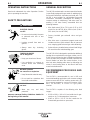
SAFETY PRECAUTIONS
ELECTRIC SHOCK
can kill.
• Do not touch electrically live parts
or electrode with skin or wet
clothing.
• Insulate yourself from work or
ground.
• Always wear dry insulating
gloves.
FUMES AND GASES
can be dangerous.
• Keep your head out of fumes.
• Use ventilation or exhaust to
remove fumes from breathing
zone.
WELDING SPARKS
can cause fire or explosion.
• Keep flammable material away.
• Do not weld on containers that
have held combustibles.
ARC RAYS
can burn.
• Wear eye, ear, and body
protection.
Observe additional Safety Guidelines detailed in
the beginning of this manual.
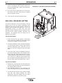
GENERAL DESCRIPTION
The LN-742 semiautomatic constant speed wire feeder
is specifically equipped for gas metal arc welding using
flux-cored Outershield electrodes and solid wire. The
LN-742 is also suitable for self-shielded flux-cored
Innershield electrodes, submerged arc welding (if
constant voltage is satisfactory), and other open arc
welding. It has been factory assembled with the
following features:
• Wire feed control [50 to 770 in./min (1.25 to 19.5
m/min) for the LN-742; 80 to 1200 in./min (2.00 to
30.5 m/min) for the LN-742H].
• Factory installed gas solenoid valve and gas
fittings.
• Wire drive uses a permanent magnet motor and
includes tool-less “quick-release” idle roll pressure
arm, outgoing guide tube and gun cable fastening.
• Optional factory installed water solenoid and fittings
for use with water cooled welding guns.
The LN-742 4-Roll is designed to provide the additional
feeding force required when using gun cables over 15
ft (4.6 m) long or when the wire is pulled long distances
(such as when bulk packages are used). Because the
four-roll feeder has twice the contact surface, it can
also help when feeding softer wires by delivering the
same or more feeding force as the two-roll with less
overall wire deformation.
RECOMMENDED PROCESSES AND
EQUIPMENT
The LN-742 is recommended for use in MIG and
Innershield welding applications with constant voltage
power sources with 42 VAC auxiliary power and a 14-
pin connector receptacle, such as the Invertec V300-
PRO, DC-650-PRO, or Lincoln CV type power
sources.
The LN-742 is capable of the following wire feed
ranges:
• 0.025 to 1/16 in. (0.6 to 1.6 mm) solid wire for gas-
metal-arc or CV submerged arc processes.
• 0.045 to 3/32 in. (1.2 to 2.4 mm) cored wire for
Outershield gas-metal-arc processes.
WARNING

B-2
OPERATION
B-2
• 0.045 to 5/64 in. (1.2 to 2.0 mm) cored wire for
Innershield processes.
The LN-742H is capable of the following wire feed
ranges:
• 0.025 to 0.045 in. (0.6 to 1.2 mm) solid wire for gas-
metal-arc or CV submerged arc processes.
• 0.045 in. (1.2 mm) cored wire for Outershield gas-
metal-arc or Innershield processes.
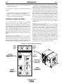
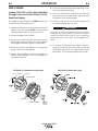
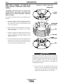
CONTROLS AND SETTINGS
The operator controls are located on the keypad
shown in Figure B.1. The keypad consists of: 7
membrane keys with tactile-feel embossed domes,
that are generously spaced to provide easy selection,
even while wearing welding gloves; a long-life, 3-1/2
digit, 7 segment LED display with 0.56 in. (14.2 mm)
character height, permitting easy viewing even from
long gun cable distances; and high intensity, red, LED
indicator lights that allow for viewing at almost any
angle.
TRIGGER MODE CONTROLS. This control enables
the operator to choose the mode of operation as
shown by the indicator lights. Pressing the key causes
the mode lights to sequence (from top to bottom). The
top light indicates standard (two-step) trigger mode. In
this mode the unit will only be active when the trigger
is pressed. The middle light indicates lock (four-step)
trigger mode. In this mode the solenoid is energized
when the trigger is pressed, the power source and
wire feeder are energized after preflow time when the
trigger is released. Closing the trigger a second time
turns off the wire feeder and then the power source
after burnback time. Releasing the trigger a second
time turns off the solenoid after Burnback time. The
bottom light indicates spot weld trigger mode. Closing
the trigger allows a single, timed, weld cycle. The
duration of the weld cycle is set with the time selection
controls. The spot on timer starts when welding
current flows.
TIME SELECTION CONTROLS. This control enables
the operator to choose which timer will be displayed
as shown by the indicator lights. Pressing the key
causes the mode lights to sequence (from top to
bottom). Any timers not available to the currently
selected mode will be skipped. Times displayed in the
LED display are adjusted using the setting adjustment
arrows to the left of the LED display. The top left light
indicates the preflow time is being displayed in
seconds. The top right indicator light indicates the
postflow time is being displayed in seconds. The
middle light indicates the burnback time is being
displayed in seconds. The bottom light indicates the
spot weld time is being displayed in seconds.
LN-742 & LN-742H
COLD INCH
OLTMETER
INCH
WFS
PREFLOW POSTFLOW
BURNBACK
SPOT
STD
LOCK
SPOT
TIMETRIGGER MODE
t1
t2
GAS PURGE
t
t
t
GAS
PURGE
KEY
LED
DISPLAY
FUNCTION
SELECTION
CONTROLS
TIMER
SELECTION
CONTROLS
SETTING
ADJUSTMENT
ARROW KEYS
TRIGGER
MODE
CONTROLS
COLD
INCH
KEY
FIGURE B.1 – WIRE FEEDER CONTROLS.

B-3
OPERATION
B-3
FUNCTION SELECTION CONTROLS. This control
enables the operator to select the function that will be
displayed as shown by the indicator lights. Pressing
the key causes the mode lights to sequence (from top
to bottom). Settings displayed in the LED display are
adjusted using the setting adjustment arrows to the
left of the LED display. The top light indicates the arc
voltage is being displayed in volts. The middle light
indicates the inch speed is being displayed. The
bottom light indicates the weld feed speed (WFS) is
being displayed.
INCREASE ARROW. This key increases the setting
of the parameter selected to be displayed, using the
“Quick-Set” feature for fast and accurate setting.
DECREASE ARROW. This key decreases the setting
of the parameter selected to be displayed, using the
“Quick-Set” feature for fast and accurate setting.
QUICK-SET FEATURE. This feature permits the
arrow keys to control each display digit one at a time.
The display digits blink in sequence from left to right.
Pressing an arrow key immediately after a digit blinks
alters that digit. Releasing the arrow key causes the
left-to-right sequencing to resume.
COLD INCH KEY. This key energizes the wire feeder
to inch the wire forward, but does not energize the
power source or solenoid valve.
GAS PURGE KEY. This key energizes the solenoid
valve to purge any remaining gasses, but does not
energize the wire feeder or power source.
ACCELERATION SETTING
Pressing both the Gas Purge key and the Function
Selection key at the same time, on the keypad shown
in Figure B.1, enables the acceleration setting display.
The LED display will indicate “A-X” with “X” being a
number from 1 (slowest) to 5 (fastest). This number is
adjusted using the setting adjustment arrow keys. To
exit the acceleration setting function, press both keys a
second time, or press any other key except for the
setting adjustment arrow keys.
ENGLISH OR METRIC SPEED
DISPLAY UNITS
Pressing both the Gas Purge key and Timer Selection
key causes the speed display units to toggle between
inches per minute (no decimal point displayed) or
meters per minute (decimal point displayed). If the LED
display is showing the voltmeter or one of the timer
settings when these keys are pressed, the display will
change to the weld speed to indicate the selected
speed display units. See Figure B.1 for key locations.
CIRCUIT PROTECTION
The LN-742 has solid-state overload protection of the
wire drive motor. If the wire drive motor becomes
overloaded for an extended period of time, the
protection circuitry turns off the power source, wire
feeder, and solenoid, then displays the error code E30
on the LED display. This indicates the wire drive motor
is overloaded, with the number indicating the time
remaining in seconds before the unit will automatically
reset. This number continues to decrement every
second until it reaches zero. At that time the unit
resets automatically and the previous display will
return indicating that the unit is ready for operation.
Over loads can result from: improper tip size, liner,
drive rolls, or guide tubes; obstructions or bends in the
gun cable; feeding wire that is larger than the rated
capacity of the feeder; or any other factors that would
impede normal wire feeding.
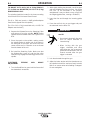
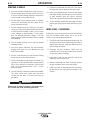
DRIVE ROLL INSTALLATION
CHANGING DRIVE ROLLS FOR TWO-
ROLL WIRE FEEDERS:
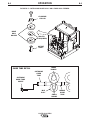
To change drive rolls on a two-roll wire feeder, refer to
Figure B.2 and perform the following steps:
1. Turn off the welding power source.
2. Rotate the latch knob on the quick release arm.
3. Remove the hex head screw and clamping collar.
Remove the drive roll from the shaft.
4. The new roll to be installed is stamped for the size
wire to be fed. An “A” after the size indicates
aluminum wire. Remove the rolls from the kit and
wipe them clean. Wipe the output shaft and locating
shoulder clean.
LN-742 & LN-742H

B-4
OPERATION
B-4
LN-742 & LN-742H
GUIDE TUBE DETAIL
OUTGOING
GUIDE TUBE
INSERT
OUTGOING
GUIDE
TUBE
LARGE
RADIUS
DRIVE
ROLL
INCOMING
GUIDE
TUBE
SMALL
RADIUS
IDLE
ROLL
CLAMPING
COLLAR
SPACER (IF REQUIRED)
OUTPUT
SHAFT
DRIVE
ROLL
HALVES
FIGURE B.2 – INSTALLING DRIVE ROLLS ON A TWO-ROLL FEEDER.

B-5
OPERATION
B-5
5. Use the clamping collar and hex head screw to
install the roll on the output shaft. Certain size drive
rolls consist of two roll halves, and may contain a
spacer. If the drive roll you are installing contains a
spacer, the spacer fits between the two halves of
the drive roll. Double grooved drive rolls are to be
installed with side stenciled for correct wire size
facing outward and with slotted spacer on top of
roll. Tighten the hex head screw.
6. Loosen the molded hand-screw on the front of the
wire drive and pull the gun connector out of the
connector block. The guide tube provided in the
gun connector is for .045” (1.2mm) or smaller wire
sizes (marked with one ring). If larger wire sizes
are used, remove and replace the guide tube with
the larger hole guide tube (marked with four rings)
which is provided in the storage hole of
appropriate capacity wire drive faceplates (near
motor). The guide tube is secured with a set
screw on the bottom of the brass hex so the guide
tube is flush with the incoming end of the gun
connector.
7. Back out the guide tube clamping screws.
Remove the old guide tubes, if installed.
8. Insert the longer guide tube into the rear hole and
the other guide tube through the front hole. The
fine wire chisel point end of the guide tube must
have the larger radius end next to the drive roll.
See Figure B.2. Push the guide tube back as far
as it will go and tighten the clamping screw. Insert
the incoming guide tube as far back as it will go
and tighten the clamping screw. The clamping
screws are dog points. When the guide tubes are
properly installed these dog points will lock into
the annular grooves in each of the guide tubes.
9. Re-install the gun connector into the conductor
block and tighten the molded hand-screw.
10. Re-latch the idle roll pressure arm.
11. Set the idle roll pressure as detailed in the Idle
Roll Pressure Setting procedure detailed later in
this section.
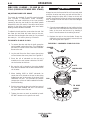
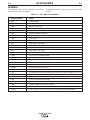
CHANGING DRIVE ROLLS FOR FOUR-
ROLL WIRE FEEDERS:
To change drive rolls on a four-roll wire feeder, refer to
Figure B.3 and perform the following steps:
1. Turn off welding power source.
2. Remove the gun and cable.
3. Open both quick release levers by moving the
levers outward and pulling them toward you.
4. Loosen the thumb screws holding the guide tubes
in place. Remove the incoming guide tube, if
installed.
5. Remove the hex head screws and clamping
collars from the output shafts. Remove the drive
rolls and middle guide tube.
6. The new rolls to be installed are stenciled with the
wire size that will be fed. An “A” after the number
indicates aluminum wire. Remove the rolls from
the kit and wipe them clean. Wipe the output
shafts and locating shoulders clean.
7. Install one roll onto the output shaft closest to the
incoming side of the feeder clamping collar and
hex head screw. Certain size drive rolls consist of
two roll halves, and may contain a spacer. If the
drive roll you are installing contains a spacer, the
spacer fits between the two halves of the drive
roll. Double grooved drive rolls are to be installed
with side stenciled for correct wire size facing
outward and with slotted spacer on top of roll.
Tighten the hex head screw.
8. Install the middle guide tube, but do not tighten at
this time. When installing a 0.035” middle guide
tube the larger radius should be aligned towards
the drive roll. Slide the guide tube up against the
installed drive roll.
9. Install the second drive roll on the remaining shaft
the same way as the first. Center the middle guide
tube between the rolls and tighten the
thumbscrews holding it in place.
10. Loosen the molded hand-screw on the front of the
wire drive and pull the gun connector out of the
connector block. The guide tube provided in the
gun connector is for .045” (1.2mm) or smaller wire
sizes (marked with one ring). If larger wire sizes
are used, remove and replace the guide tube with
the larger hole guide tube (marked with four rings)
which is provided in the storage hole of
appropriate capacity wire drive faceplates (near
motor). The guide tube is secured with a set
screw on the bottom of the brass hex so the guide
tube is flush with the incoming end of the gun
connector.
11. With the gun connector removed, back out the
screws for the outgoing guide tube.
12. Install the outgoing guide tube in the front hole.
Be certain that the proper plastic insert is used.
For proper installation of the outgoing guide tube
insert, refer to Figure B.3. The fine wire chisel
point tube must
have largest radius next to drive
roll. Tighten in place.
13. Re-install the gun connector into the conductor
block and tighten the molded hand-screw.
LN-742 & LN-742H

B-6
OPERATION
B-6
LN-742 & LN-742H
FIGURE B.3 – INSTALLING DRIVE ROLLS ON A FOUR-ROLL FEEDER.
GUIDE TUBE DETAIL
OUTGOING
GUIDE TUBE
INSERT
OUTGOING
GUIDE
TUBE
MIDDLE
GUIDE
TUBE
SMALL
RADIUS
IDLE
ROLL
LARGE
RADIUS
CLAMPING
COLLAR
OUTPUT
SHAFT
SPACER
(IF REQUIRED)
DRIVE
ROLL
HALVES
La page charge ...
La page charge ...
La page charge ...
La page charge ...
La page charge ...
La page charge ...
La page charge ...
La page charge ...
La page charge ...
La page charge ...
La page charge ...
La page charge ...
La page charge ...
La page charge ...
La page charge ...
La page charge ...
La page charge ...
La page charge ...
La page charge ...
La page charge ...
La page charge ...
La page charge ...
La page charge ...
La page charge ...
La page charge ...
La page charge ...
La page charge ...
La page charge ...
-
 1
1
-
 2
2
-
 3
3
-
 4
4
-
 5
5
-
 6
6
-
 7
7
-
 8
8
-
 9
9
-
 10
10
-
 11
11
-
 12
12
-
 13
13
-
 14
14
-
 15
15
-
 16
16
-
 17
17
-
 18
18
-
 19
19
-
 20
20
-
 21
21
-
 22
22
-
 23
23
-
 24
24
-
 25
25
-
 26
26
-
 27
27
-
 28
28
-
 29
29
-
 30
30
-
 31
31
-
 32
32
-
 33
33
-
 34
34
-
 35
35
-
 36
36
-
 37
37
-
 38
38
-
 39
39
-
 40
40
-
 41
41
-
 42
42
-
 43
43
-
 44
44
-
 45
45
-
 46
46
-
 47
47
-
 48
48


Lincoln Electric LN-742 Mode d'emploi
- Catégorie
- Système de soudage
- Taper
- Mode d'emploi
- Ce manuel convient également à
dans d''autres langues
Documents connexes
-
Lincoln Electric IM886 Manuel utilisateur
-
-
-
-
-
-
-
-
-
Lincoln Electric Ranger 305D Mode d'emploi