Simplicity 120202-0128-B8 Manuel utilisateur
- Catégorie
- Accessoires pour véhicules automobiles
- Taper
- Manuel utilisateur

Not for
Reproduction
80006749USCN
Copyright © Briggs & Stratton Corporation
Milwaukee, WI, USA. All rights reserved.
BRIGGS & STRATTON is a registered
trademark of Briggs & Stratton Corporation.
Revision: C


Not for
Reproduction
12
13
14
15
16
17
18
19
20
3

Not for
Reproduction
Copyright © Briggs & Stratton Corporation, Milwaukee, WI, USA. All rights reserved.
This manual contains safety information to make you aware of the hazards and risks
associated with engines and how to avoid them. It also contains instructions for the proper
use and care of the engine. Because Briggs & Stratton Corporation does not necessarily
know what equipment this engine will power, it is important that you read and understand
these instructions and the instructions for the equipment. Save these original instructions
for future reference.
Note:
The figures and illustrations in this manual are provided for reference only and may
differ from your specific model. Contact your dealer if you have questions.
For replacement parts or technical assistance, record below the engine model, type, and
code numbers along with the date of purchase. These numbers are located on your engine
(see the
Features and Controls
section).
Date of Purchase
Engine Model - Type - Trim
Engine Serial Number
Look for the 2D barcode located on some
engines. When viewed with a 2D-capable
device, the code will bring up our website
where you can access support information
for this product. Data rates apply. Some
countries may not have online support
information available.
Operator Safety
Safety Alert Symbol and Signal Words
The safety alert symbol is used to identify safety information about hazards that can
result in personal injury. A signal word (DANGER, WARNING, or CAUTION) is used with
the alert symbol to indicate the likelihood and the potential severity of injury. In addition, a
hazard symbol may be used to represent the type of hazard.
DANGER indicates a hazard which, if not avoided, will result in death or serious
injury.
WARNING indicates a hazard which, if not avoided, could result in death or serious
injury.
CAUTION indicates a hazard which, if not avoided, could result in minor or
moderate injury.
NOTICE
indicates an situation that could result in damage to the product.
Hazard Symbols and Meanings
MeaningSymbolMeaningSymbol
Read and understand the
Operator's Manual before
operating or servicing the unit.
Safety information about
hazards that can result in
personal injury.
Explosion hazardFire hazard
Toxic fume hazardShock hazard
Noise hazard - Ear protection
recommended for extended
use.
Hot surface hazard
MeaningSymbolMeaningSymbol
Explosion hazardThrown object hazard -
Wear eye protection.
Kickback hazardFrostbite hazard
Chemical HazardAmputation hazard - moving
parts
CorrosiveThermal heat hazard
Safety Messages
WARNING
Certain components in this product and its related accessories contain chemicals
known to the State of California to cause cancer, birth defects, or other reproductive
harm. Wash hands after handling.
WARNING
The engine exhaust from this product contains chemicals known to the State of
California to cause cancer, birth defects, or other reproductive harm.
WARNING
Briggs & Stratton Engines are not designed for and are not to be used to power: fun-
karts; go-karts; children's, recreational, or sport all-terrain vehicles (ATVs); motorbikes;
hovercraft; aircraft products; or vehicles used in competitive events not sanctioned by
Briggs & Stratton. For information about competitive racing products, see
www.briggsracing.com. For use with utility and side-by-side ATVs, please contact
Briggs & Stratton Engine Application Center, 1-866-927-3349. Improper engine
application may result in serious injury or death.
WARNING
Fuel and its vapors are extremely flammable and explosive.
Fire or explosion can cause severe burns or death.
When Adding Fuel
• Turn engine off and let engine cool at least 2 minutes before removing the fuel cap.
• Fill fuel tank outdoors or in well-ventilated area.
• Do not overfill fuel tank. To allow for expansion of the fuel, do not fill above the
bottom of the fuel tank neck.
• Keep fuel away from sparks, open flames, pilot lights, heat, and other ignition
sources.
• Check fuel lines, tank, cap, and fittings frequently for cracks or leaks. Replace if
necessary.
• If fuel spills, wait until it evaporates before starting engine.
When Starting Engine
• Ensure that spark plug, muffler, fuel cap and air cleaner (if equipped) are in place
and secured.
• Do not crank engine with spark plug removed.
• If engine floods, set choke (if equipped) to OPEN / RUN position, move throttle (if
equipped) to FAST position and crank until engine starts.
When Operating Equipment
• Do not tip engine or equipment at angle which causes fuel to spill.
4 BRIGGSandSTRATTON.com

Not for
Reproduction
• Do not choke the carburetor to stop engine.
• Never start or run the engine with the air cleaner assembly (if equipped) or the air
filter (if equipped) removed.
When Changing Oil
• If you drain the oil from the top oil fill tube, the fuel tank must be empty or fuel can
leak out and result in a fire or explosion.
When Tipping Unit for Maintenance
• When performing maintenance that requires the unit to be tipped, the fuel tank, if
mounted on the engine, must be empty or fuel can leak out and result in a fire or
explosion.
When Transporting Equipment
• Transport with fuel tank EMPTY or with fuel shut-off valve in the CLOSED position.
When Storing Fuel Or Equipment With Fuel In Tank
• Store away from furnaces, stoves, water heaters or other appliances that have pilot
lights or other ignition sources because they can ignite fuel vapors.
WARNING
Starting engine creates sparking.
Sparking can ignite nearby flammable gases.
Explosion and fire could result.
• If there is natural or LP gas leakage in area, do not start engine.
• Do not use pressurized starting fluids because vapors are flammable.
WARNING
POISONOUS GAS HAZARD. Engine exhaust contains carbon monoxide, a
poisonous gas that could kill you in minutes. You CANNOT see it, smell it, or
taste it. Even if you do not smell exhaust fumes, you could still be exposed to
carbon monoxide gas. If you start to feel sick, dizzy, or weak while using this
product, get to fresh air RIGHT AWAY. See a doctor. You may have carbon
monoxide poisoning.
• Operate this product ONLY outside far away from windows, doors and vents to
reduce the risk of carbon monoxide gas from accumulating and potentially being
drawn towards occupied spaces.
• Install battery-operated carbon monoxide alarms or plug-in carbon monoxide alarms
with battery back-up according to the manufacturer's instructions. Smoke alarms
cannot detect carbon monoxide gas.
• DO NOT run this product inside homes, garages, basements, crawlspaces, sheds,
or other partially-enclosed spaces even if using fans or opening doors and windows
for ventilation. Carbon monoxide can quickly build up in these spaces and can linger
for hours, even after this product has shut off.
• ALWAYS place this product downwind and point the engine exhaust away from
occupied spaces.
WARNING
Rapid retraction of starter cord (kickback) will pull hand and arm toward engine
faster than you can let go.
Broken bones, fractures, bruises or sprains could result.
• When starting engine, pull the starter cord slowly until resistance is felt and then
pull rapidly to avoid kickback.
• Remove all external equipment / engine loads before starting engine.
• Direct-coupled equipment components such as, but not limited to, blades, impellers,
pulleys, sprockets, etc., must be securely attached.
WARNING
Rotating parts can contact or entangle hands, feet, hair, clothing, or accessories.
Traumatic amputation or severe laceration can result.
• Operate equipment with guards in place.
• Keep hands and feet away from rotating parts.
• Tie up long hair and remove jewelry.
• Do not wear loose-fitting clothing, dangling drawstrings or items that could become
caught.
WARNING
Running engines produce heat. Engine parts, especially muffler, become
extremely hot.
Severe thermal burns can occur on contact.
Combustible debris, such as leaves, grass, brush, etc. can catch fire.
• Allow muffler, engine cylinder and fins to cool before touching.
• Remove accumulated debris from muffler area and cylinder area.
• It is a violation of California Public Resource Code, Section 4442, to use or operate
the engine on any forest-covered, brush-covered, or grass-covered land unless the
exhaust system is equipped with a spark arrester, as defined in Section 4442,
maintained in effective working order. Other states or federal jurisdictions may have
similar laws. Contact the original equipment manufacturer, retailer, or dealer to
obtain a spark arrester designed for the exhaust system installed on this engine.
WARNING
Unintentional sparking can result in fire or electric shock.
Unintentional start-up can result in entanglement, traumatic amputation, or
laceration.
Fire hazard
Before performing adjustments or repairs:
• Disconnect the spark plug wire and keep it away from the spark plug.
• Disconnect battery at negative terminal (only engines with electric start.)
• Use only correct tools.
• Do not tamper with governor spring, links or other parts to increase engine speed.
• Replacement parts must be of the same design and installed in the same position
as the original parts. Other parts may not perform as well, may damage the unit,
and may result in injury.
• Do not strike the flywheel with a hammer or hard object because the flywheel may
later shatter during operation.
When testing for spark:
• Use approved spark plug tester.
• Do not check for spark with spark plug removed.
Features and Controls
Engine Controls
Compare the illustration (Figure: 1, 2, 3) with your engine to familiarize yourself with the
location of various features and controls.
A. Engine Identification Numbers Model - Type - Code
B. Spark Plug
C. Air Cleaner (flat or oval)
D. Choke Control
E. Fuel Shut-off (if equipped)
F. Starter Cord Handle
G. Air Intake Grille
H. Throttle Control (if equipped)
I. Stop Switch (if equipped)
J. Fuel Tank and Cap
K. Extended Dipstick (if equipped)
L. Short Dipstick (if equipped)
M. Oil Drain Plug
N. Oil Fill
O. Muffler, Muffler Guard (if equipped), Spark Arrester (if equipped)
5

Not for
Reproduction
P. Safety Key (electric start models)
Q. ON/OFF Switch (electric start models)
R. Gear Reduction Unit (if equipped)
S. Key Switch (electric start models)
Engine Control Symbols and Meanings
MeaningSymbolMeaningSymbol
Engine speed - SLOWEngine speed - FAST
ON - OFFEngine speed - STOP
Engine start - Choke OPENEngine start - Choke
CLOSED
Fuel Shut-off - CLOSEDFuel Cap
Fuel Shut-off - OPEN
Fuel level - Maximum
Do not overfill
Operation
Oil Recommendations
Oil Capacity: See the
Specifications
section.
NOTICE
This engine was shipped from Briggs & Stratton without oil. Equipment manufacturers
or dealers may have added oil to the engine. Before you start the engine for the first
time, make sure to check the oil level and add oil according to the instructions in this
manual. If you start the engine without oil, it will be damaged beyond repair and will not
be covered under warranty.
We recommend the use of Briggs & Stratton Warranty Certified oils for best performance.
Other high-quality detergent oils are acceptable if classified for service SF, SG, SH, SJ or
higher. Do not use special additives.
Outdoor temperatures determine the proper oil viscosity for the engine. Use the chart to
select the best viscosity for the outdoor temperature range expected. Engines on most
outdoor power equipment operate well with 5W-30 Synthetic oil. For equipment operated
in hot temperatures, Vanguard™ 15W-50 Synthetic oil provides the best protection.
SAE 30 - Below 40 °F (4 °C) the use of SAE 30 will result in hard starting.A
10W-30 - Above 80 °F (27 °C) the use of 10W-30 may cause increased oil
consumption. Check oil level more frequently.
B
5W-30C
Synthetic 5W-30D
Vanguard™ Synthetic 15W-50E
Check Oil Level
See Figure: 4, 5
Before adding or checking the oil
• Make sure the engine is level.
• Clean the oil fill area of any debris.
Oil Fill Cap, if equipped
1. Remove the oil fill cap (A, Figure 4).
2. If oil level is low, slowly add oil into the engine oil fill (B, Figure 4). Fill to point of
overflowing.
3. Reinstall and tighten the oil fill cap (A, Figure 4).
Short Dipstick, if equipped
1. Remove the dipstick (C, Figure 4) and wipe with a clean cloth.
2. Install the dipstick (C, Figure 4). Do not turn or tighten.
3. Remove the dipstick and check the oil level. Correct oil level is at the top of the full
indicator (D, Figure 4) on the dipstick.
4. If oil level is low, slowly add oil into the engine oil fill (B, Figure 4). Fill to point of
overflowing.
5. Reinstall and tighten the dipstick (C, Figure 4).
Extended Dipstick, if equipped
1. Remove the dipstick (A, Figure 5) and wipe with a clean cloth.
2. Install and tighten the dipstick (A, Figure 5).
3. Remove the dipstick and check the oil level. Correct oil level is at the top of the full
indicator (B, Figure 5) on the dipstick.
4. If oil level is low, slowly add oil into the engine oil fill (C, Figure 5). Do not overfill.
After adding oil, wait one minute and then recheck the oil level.
5. Reinstall and tighten the dipstick (A, Figure 5).
Low Oil Protection System (if equipped)
Some engines are equipped with a low oil sensor. If the oil is low, the sensor will either
activate a warning light or stop the engine. Stop the engine and follow these steps before
restarting the engine.
• Make sure the engine is level.
• Check the oil level. See the
Check Oil Level
section.
• If the oil level is low, add the proper amount of oil. Start the engine and make sure
the warning light (if equipped) is not activated.
• If the oil level is not low, do not start the engine. Contact a Briggs & Stratton
Authorized Service Dealer to have the oil problem corrected.
Fuel Recommendations
Fuel must meet these requirements:
• Clean, fresh, unleaded gasoline.
• A minimum of 87 octane/87 AKI (91 RON). High altitude use, see below.
• Gasoline with up to 10% ethanol (gasohol) is acceptable.
NOTICE
Do not use unapproved gasolines, such as E15 and E85. Do not mix oil in
gasoline or modify the engine to run on alternate fuels. Use of unapproved fuels will
damage the engine components, which will not be covered under warranty.
To protect the fuel system from gum formation, mix a fuel stabilizer into the fuel. See
Storage.
All fuel is not the same. If starting or performance problems occur, change fuel
providers or change brands. This engine is certified to operate on gasoline. The emissions
control system for this engine is EM (Engine Modifications).
6 BRIGGSandSTRATTON.com

Not for
Reproduction
High Altitude
At altitudes over 5,000 feet (1524 meters), a minimum 85 octane/85 AKI (89 RON) gasoline
is acceptable.
For carbureted engines, high altitude adjustment is required to maintain performance.
Operation without this adjustment will cause decreased performance, increased fuel
consumption, and increased emissions. Contact a Briggs & Stratton Authorized Service
Dealer for high altitude adjustment information. Operation of the engine at altitudes below
2,500 feet (762 meters) with the high altitude adjustment is not recommended.
For Electronic Fuel Injection (EFI) engines, no high altitude adjustment is necessary.
Add Fuel
See Figure: 6
WARNING
Fuel and its vapors are extremely flammable and explosive.
Fire or explosion can cause severe burns or death.
When adding fuel
• Turn engine off and let engine cool at least 2 minutes before removing the fuel cap.
• Fill fuel tank outdoors or in well-ventilated area.
• Do not overfill fuel tank. To allow for expansion of the fuel, do not fill above the bottom
of the fuel tank neck.
• Keep fuel away from sparks, open flames, pilot lights, heat, and other ignition sources.
• Check fuel lines, tank, cap, and fittings frequently for cracks or leaks. Replace if
necessary.
• If fuel spills, wait until it evaporates before starting engine.
1. Clean the fuel cap area of dirt and debris. Remove the fuel cap.
2. Fill the fuel tank (A, Figure 6) with fuel. To allow for expansion of the fuel, do not fill
above the bottom of the fuel tank neck (B).
3. Reinstall the fuel cap.
Start and Stop Engine
See Figure: 7, 8
Start Engine
WARNING
Rapid retraction of starter cord (kickback) will pull hand and arm toward engine
faster than you can let go.
Broken bones, fractures, bruises or sprains could result.
• When starting engine, pull the starter cord slowly until resistance is felt and then pull
rapidly to avoid kickback.
WARNING
Fuel and its vapors are extremely flammable and explosive.
Fire or explosion can cause severe burns or death.
When Starting Engine
• Ensure that spark plug, muffler, fuel cap and air cleaner (if equipped) are in place
and secured.
• Do not crank engine with spark plug removed.
• If engine floods, set choke (if equipped) to OPEN / RUN position, move throttle (if
equipped) to FAST position and crank until engine starts.
WARNING
POISONOUS GAS HAZARD. Engine exhaust contains carbon monoxide, a
poisonous gas that could kill you in minutes. You CANNOT see it, smell it, or taste
it. Even if you do not smell exhaust fumes, you could still be exposed to carbon
monoxide gas. If you start to feel sick, dizzy, or weak while using this product,
shut it off and get to fresh air RIGHT AWAY. See a doctor. You may have carbon
monoxide poisoning.
• Operate this product ONLY outside far away from windows, doors and vents to reduce
the risk of carbon monoxide gas from accumulating and potentially being drawn
towards occupied spaces.
• Install battery-operated carbon monoxide alarms or plug-in carbon monoxide alarms
with battery back-up according to the manufacturer's instructions. Smoke alarms
cannot detect carbon monoxide gas.
• DO NOT run this product inside homes, garages, basements, crawlspaces, sheds,
or other partially-enclosed spaces even if using fans or opening doors and windows
for ventilation. Carbon monoxide can quickly build up in these spaces and can linger
for hours, even after this product has shut off.
• ALWAYS place this product downwind and point the engine exhaust away from
occupied spaces.
NOTICE
This engine was shipped from Briggs & Stratton without oil. Before you start
the engine, make sure you add oil according to the instructions in this manual. If you
start the engine without oil, it will be damaged beyond repair and will not be covered
under warranty.
Note:
Equipment may have remote controls. See the equipment manual for location and
operation of remote controls.
1. Check the engine oil. See the
Check Oil Level
section.
2. Make sure equipment drive controls, if equipped, are disengaged.
3. Move the fuel shut-off (A, Figure 7) to the open position.
4. Move the throttle control (C, Figure 7), if equipped, to the fast position. Operate the
engine in the fast position.
5. Move the choke control (B, Figure 7), to the choke position.
Note:
Choke is usually unnecessary when restarting a warm engine.
6. Move the stop switch (D, Figure 7), if equipped, to the on position.
7. Rewind Start, if equipped: Firmly hold the starter cord handle (E, Figure 7). Pull
the starter cord handle slowly until resistance is felt, then pull rapidly.
WARNING
Rapid retraction of the starter cord (kickback) will pull your hand and arm toward the
engine faster than you can let go. Broken bones, fractures, bruises or sprains could
result. When starting engine, pull the starter cord slowly until resistance is felt and then
pull rapidly to avoid kickback.
8. Electric Start, if equipped with Safety Key (F): Push in the safety key (F, Figure
7). Momentarily push the start switch (G). When the engine starts, release the start
switch.
9. Electric Start, if equipped with Automotive Key Switch (H): Turn the key switch
(H, Figure 8) to the start position. When the engine starts, release the key switch.
NOTICE
To extend the life of the starter, use short starting cycles (five seconds
maximum). Wait one minute between starting cycles.
10. As the engine warms up, move the choke control (B, Figure 7) to the run position.
Note:
If the engine does not start after repeated attempts, go to
BRIGGSandSTRATTON.com or contact your local dealer or call 1-800-233-3723 (in
USA).
Stop Engine
WARNING
Fuel and its vapors are extremely flammable and explosive.
Fire or explosion can cause severe burns or death.
• Do not choke the carburetor to stop the engine.
1. Throttle Control, if equipped: Move the throttle control lever (C, Figure 7) to the
slow and then to the stop position.
Stop Switch, if equipped: Move the stop switch (D, Figure 7) to the stop position.
Safety Key, if equipped: Remove the safety key (F, Figure 7) and keep it in a safe
place out of the reach of children.
Key Switch, if equipped: Turn the key switch (H, Figure 8) to the off position.
Remove the key and keep in a safe place out of the reach of children.
2. After the engine stops, move the fuel shut-off (A, Figure 7) to the closed position.
7

Not for
Reproduction
Maintenance
NOTICE
If the engine is tipped during maintenance, the fuel tank, if mounted on
engine, must be empty and the spark plug side must be up. If the fuel tank is not empty
and if the engine is tipped in any other direction, it may be difficult to start due to oil or
gasoline contaminating the air filter and/or the spark plug.
WARNING
When performing maintenance that requires the unit to be tipped, the fuel tank, if mounted
on the engine, must be empty or fuel can leak out and result in a fire or explosion.
We recommend that you see any Briggs & Stratton Authorized Service Dealer for all
maintenance and service of the engine and engine parts.
NOTICE
All the components used to build this engine must remain in place for proper
operation.
WARNING
Unintentional sparking can result in fire or electric shock.
Unintentional start-up can result in entanglement, traumatic amputation, or
laceration.
Fire hazard
Before performing adjustments or repairs:
• Disconnect the spark plug wire and keep it away from the spark plug.
• Disconnect battery at negative terminal (only engines with electric start.)
• Use only correct tools.
• Do not tamper with governor spring, links or other parts to increase engine speed.
• Replacement parts must be of the same design and installed in the same position
as the original parts. Other parts may not perform as well, may damage the unit, and
may result in injury.
• Do not strike the flywheel with a hammer or hard object because the flywheel may
later shatter during operation.
When testing for spark:
• Use approved spark plug tester.
• Do not check for spark with spark plug removed.
Emissions Control Service
Maintenance, replacement, or repair of the emissions control devices and systems
may be performed by any off-road engine repair establishment or individual. However,
to obtain "no charge" emissions control service, the work must be performed by a factory
authorized dealer. See the Emissions Control Statements.
Maintenance Schedule
First 5 Hours
• Change oil
Every 8 Hours or Daily
• Check engine oil level
• Clean area around muffler and controls
• Clean air intake grille
Every 25 Hours or Annually
• Clean air filter
1
• Clean pre-cleaner (if equipped)
1
Every 50 Hours or Annually
• Change engine oil
• Service exhaust system
Every 100 Hours
• Change gear reduction oil (if equipped)
Annually
• Replace spark plug
• Replace air filter
• Replace pre-cleaner (if equipped)
• Replace fuel filter (if equipped)
• Service fuel system
• Service cooling system
1
• Check valve clearance
2
1
In dusty conditions or when airborne debris is present, clean more often.
2
Not required unless engine performance problems are noted.
Carburetor and Engine Speed
Never make adjustments to the carburetor or engine speed. The carburetor was set at the
factory to operate efficiently under most conditions. Do not tamper with the governor spring,
linkages, or other parts to change the engine speed. If any adjustments are required contact
a Briggs & Stratton Authorized Service Dealer for service.
NOTICE
The equipment manufacturer specifies the maximum speed for the engine
as installed on the equipment. Do not exceed this speed. If you are unsure what the
equipment maximum speed is, or what the engine speed is set to from the factory,
contact a Briggs & Stratton Authorized Service Dealer for assistance. For safe and
proper operation of the equipment, the engine speed should be adjusted only by a
qualified service technician.
Service Spark Plug
See Figure: 9
Check the gap (A, Figure 9) with a wire gauge (B). If necessary, reset the gap. Install and
tighten the spark plug to the recommended torque. For gap setting or torque, see the
Specifications
section.
Note:
In some areas, local law requires using a resistor spark plug to suppress ignition
signals. If this engine was originally equipped with a resistor spark plug, use the same type
for replacement.
Service Exhaust System
WARNING
Running engines produce heat. Engine parts, especially muffler, become extremely
hot.
Severe thermal burns can occur on contact.
Combustible debris, such as leaves, grass, brush, etc. can catch fire.
• Allow muffler, engine cylinder and fins to cool before touching.
• Remove accumulated debris from muffler area and cylinder area.
• It is a violation of California Public Resource Code, Section 4442, to use or operate
the engine on any forest-covered, brush-covered, or grass-covered land unless the
exhaust system is equipped with a spark arrester, as defined in Section 4442,
maintained in effective working order. Other states or federal jurisdictions may have
similar laws. Contact the original equipment manufacturer, retailer, or dealer to obtain
a spark arrester designed for the exhaust system installed on this engine.
Remove accumulated debris from muffler and cylinder area. Inspect the muffler for cracks,
corrosion, or other damage. Remove the deflector or the spark arrester, if equipped, and
inspect for damage or carbon blockage. If damage is found, install replacement parts before
operating.
WARNING
Replacement parts must be of the same design and installed in the same position as
the original parts. Other parts may not perform as well, may damage the unit, and may
result in injury.
Change Engine Oil
See Figure: 10, 11, 12
Used oil is a hazardous waste product and must be disposed of properly. Do not discard
with household waste. Check with your local authorities, service center, or dealer for safe
disposal/recycling facilities.
8 BRIGGSandSTRATTON.com

Not for
Reproduction
Remove Oil
1. With engine off but still warm, disconnect the spark plug wire (D, Figure 10) and keep
it away from the spark plug (E).
2. Remove the oil drain plug (F, Figure 11). Drain the oil into an approved container.
Note:
Any of the oil drain plugs (G, Figure 11) may be installed in the engine.
3. After the oil has drained, install and tighten the oil drain plug (F, Figure 11).
Add Oil
• Make sure the engine is level.
• Clean the oil fill area of any debris.
• See the
Specifications
section for oil capacity.
Oil Fill Cap, if equipped
1. Remove the oil fill cap (H, Figure 11).
2. Pour the oil slowly into the engine oil fill (C, Figure 11). Fill to point of overflowing.
3. Install and tighten the oil fill cap (H, Figure 11).
4. Connect the spark plug wire (D, Figure 10) to the spark plug (E).
Short Dipstick, if equipped
1. Remove the dipstick (A, Figure 11) and wipe with a clean cloth.
2. Slowly pour oil into the engine oil fill (C, Figure 11). Fill to point of overflowing.
3. Install the dipstick (A, Figure 11). Do not turn or tighten. Remove and check the
oil level. Correct oil level is at the top of the full indicator (B) on the dipstick.
4. Reinstall and tighten the dipstick (A, Figure 11).
5. Connect the spark plug wire (D, Figure 10) to the spark plug (E).
Extended Dipstick, if equipped
1. Remove the dipstick (A, Figure 12) and wipe with a clean cloth.
2. Slowly pour oil into the engine oil fill (C, Figure 12). Do not overfill. After adding oil,
wait one (1) minute and then recheck the oil level.
3. Install and tighten the dipstick (A, Figure 12).
4. Remove and check the oil level. Correct oil level is at the top of the full indicator (B,
Figure 12) on the dipstick.
5. Reinstall and tighten the dipstick (A, Figure 12).
6. Connect the spark plug wire (D, Figure 10) to the spark plug (E).
Change Gear Reduction Oil
See Figure: 13, 14
6:1 Gear Reduction (Figure 13)
If your engine is equipped with a 6:1 gear reduction unit, service as follows:
1. Remove the oil fill plug (A, Figure 13) and the oil level plug (B).
2. Remove the oil drain plug (C, Figure 13) and drain the oil into an appropriate
receptacle.
3. Reinstall and tighten the oil drain plug (C, Figure 13).
4. To refill, slowly pour gear lube (see
Specifications
section) into the oil fill hole (D,
Figure 13). Continue to pour until the oil runs out of the oil level hole (E).
5. Reinstall and tighten the oil level plug (B, Figure 13).
6. Reinstall and tighten the oil fill plug (A, Figure 13).
Note:
The oil fill plug (A, Figure 13) has a vent hole (F) and must be installed on the top
of the gear case cover as shown.
2:1 Gear Reduction (Figure 14)
The 2:1 gear reduction unit (G, Figure 14) does not require an oil change.
Service Air Filter
See Figure: 15, 16, 17
WARNING
Fuel and its vapors are extremely flammable and explosive.
Fire or explosion can cause severe burns or death.
• Never start and run the engine with the air cleaner assembly (if equipped) or the air
filter (if equipped) removed.
NOTICE
Do not use pressurized air or solvents to clean the filter. Pressurized air can
damage the filter and solvents will dissolve the filter.
See the
Maintenance Schedule
for service requirements.
Various models use either a foam or a paper filter. Some models may also have an optional
pre-cleaner that can be washed and reused. Compare the illustrations in this manual with
the type installed on your engine and service as follows.
Paper Air Filter
1. Loosen the fastener(s) (A, Figure 15, 16).
2. Remove the cover (B, Figure 15, 16).
3. Remove the pre-cleaner (C, Figure 15, 16), if equipped, and the filter (D).
4. To loosen debris, gently tap the filter (D, Figure 15, 16) on a hard surface. If the filter
is excessively dirty, replace with a new filter.
5. Wash the pre-cleaner (C, Figure 15, 16), if equipped, in liquid detergent and water.
Allow the pre-cleaner to thoroughly air dry. Do not oil the pre-cleaner.
6. Assemble the dry pre-cleaner (C, Figure 15, 16), if equipped, to the filter (D) with the
lip (G) of the pre-cleaner on the bottom of the filter pleats.
7. Install the filter (D, Figure 15, 16).
8. On models equipped with air filter shown in Figure 15, install the cover tabs (E) into
the slots (F).
9. Install the cover (B, Figure 15, 16) and secure with the fastener(s) (A).
Paper Air Filter
1. Loosen the fastener(s) (A, Figure 17).
2. Remove the cover (B, Figure 17).
3. Remove the pre-cleaner (C, Figure 17), if equipped, and the filter (D).
4. To loosen debris, gently tap the filter (D, Figure 17) on a hard surface. If the filter is
excessively dirty, replace with a new filter.
5. Remove the pre-cleaner (C, Figure 17), if equipped, from the filter (D).
6. Wash the pre-cleaner (C, Figure 17), if equipped, in liquid detergent and water. Allow
the pre-cleaner to thoroughly air dry. Do not oil the pre-cleaner.
7. Assemble the dry pre-cleaner (C, Figure 17), if equipped, to the filter (D).
8. Install the filter (D, Figure 17) and pre-cleaner (C), if equipped, into the base (E) and
onto stud (F). Make sure the filter fits securely on base.
9. Install the air filter cover (B, Figure 17) and secure with the fastener(s) (A). Make
sure the fastener(s) is tight.
Service Fuel System
See Figure: 18, 19
WARNING
Fuel and its vapors are extremely flammable and explosive.
Fire or explosion can cause severe burns or death.
• Keep fuel away from sparks, open flames, pilot lights, heat, and other ignition sources.
• Check fuel lines, tank, cap, and fittings frequently for cracks or leaks. Replace if
necessary.
• Before cleaning or replacing the fuel filter, drain the fuel tank or close the fuel shut-
off valve.
• If fuel spills, wait until it evaporates before starting engine.
• Replacement parts must be the same and installed in the same position as the original
parts.
9

Not for
Reproduction
Fuel Filter, if equipped
1. Before cleaning or replacing the fuel filter (A, Figure 18), drain the fuel tank or close
the fuel shut-off valve. Otherwise, fuel can leak out and cause a fire or explosion.
2. Use pliers to squeeze tabs (B, Figure 18) on the clamps (C), then slide the clamps
away from the fuel filter (A). Twist and pull the fuel lines (D) off of the fuel filter.
3. Check the fuel lines (D, Figure 18) for cracks or leaks. Replace if necessary.
4. Replace the fuel filter (A, Figure 18) with an original equipment replacement filter.
5. Secure the fuel lines (D, Figure 18) with clamps (C) as shown.
Fuel Strainer, if equipped
1. Remove the fuel cap (A, Figure 19).
2. Remove the fuel strainer (B, Figure 19).
3. If the fuel strainer is dirty, clean or replace it. If you replace the fuel strainer, make
sure to use an original equipment replacement fuel strainer.
Service Cooling System
WARNING
Running engines produce heat. Engine parts, especially muffler, become extremely
hot.
Severe thermal burns can occur on contact.
Combustible debris, such as leaves, grass, brush, etc., can catch fire.
• Allow muffler, engine cylinder and fins to cool before touching.
• Remove accumulated debris from muffler area and cylinder area.
NOTICE
Do not use water to clean the engine. Water could contaminate the fuel
system. Use a brush or dry cloth to clean the engine.
This is an air cooled engine. Dirt or debris can restrict air flow and cause the engine to
overheat, resulting in poor performance and reduced engine life.
1. Use a brush or dry cloth to remove debris from the air intake grille.
2. Keep linkage, springs and controls clean.
3. Keep the area around and behind the muffler, if equipped, free of any combustible
debris.
4. Make sure the oil cooler fins, if equipped, are free of dirt and debris.
After a period of time, debris can accumulate in the cylinder cooling fins and cause the
engine to overheat. This debris cannot be removed without partial disassembly of the
engine. Have a Briggs & Stratton Authorized Service Dealer inspect and clean the air
cooling system as recommended in the
Maintenance Schedule.
Storage
WARNING
Fuel and its vapors are extremely flammable and explosive.
Fire or explosion can cause severe burns or death.
When Storing Fuel Or Equipment With Fuel In Tank
• Store away from furnaces, stoves, water heaters or other appliances that have pilot
lights or other ignition sources because they can ignite fuel vapors.
Fuel System
See Figure: 20
Store the engine level (normal operating position). Fill fuel tank (A, Figure 20) with fuel.
To allow for expansion of fuel, do not overfill above the fuel tank neck (B).
Fuel can become stale when stored over 30 days. Stale fuel causes acid and gum deposits
to form in the fuel system or on essential carburetor parts. To keep fuel fresh, use Briggs
& Stratton Advanced Formula Fuel Treatment & Stabilizer, available wherever Briggs
& Stratton genuine service parts are sold.
There is no need to drain gasoline from the engine if a fuel stabilizer is added according
to instructions. Run the engine for two (2) minutes to circulate the stabilizer throughout the
fuel system before storage.
If gasoline in the engine has not been treated with a fuel stabilizer, it must be drained into
an approved container. Run the engine until it stops from lack of fuel. The use of a fuel
stabilizer in the storage container is recommended to maintain freshness.
Engine Oil
While the engine is still warm, change the engine oil. See the
Change Engine Oil
section.
Troubleshooting
For assistance, contact your local dealer or go to BRIGGSandSTRATTON.com or call
1-800-233-3723 (in USA).
Specifications
Model: 120000
12.48 ci (205 cc)Displacement
2.688 in (65,28 mm)Bore
2.200 in (55,88 mm)Stroke
18 - 20 oz (,54 - ,59 L)Oil Capacity
80W-90Gear Reduction Oil Type
4 oz (0,12 L)Gear Reduction Oil Capacity
.030 in (,76 mm)Spark Plug Gap
180 lb-in (20 Nm)Spark Plug Torque
.010 - .014 in (,25 - ,36 mm)Armature Air Gap
.004 - .006 in (,10 - ,15 mm)Intake Valve Clearance
.009 - .011 in (,23 - ,28 mm)Exhaust Valve Clearance
Model: 150000
15.24 ci (250 cc)Displacement
2.970 in (75,44 mm)Bore
2.200 in (55,88 mm)Stroke
18 - 20 oz (,54 - ,59 L)Oil Capacity
80W-90Gear Reduction Oil Type
4 oz (0,12 L)Gear Reduction Oil Capacity
.030 in (,76 mm)Spark Plug Gap
180 lb-in (20 Nm)Spark Plug Torque
.010 - .014 in (,25 - ,36 mm)Armature Air Gap
.004 - .006 in (,10 - ,15 mm)Intake Valve Clearance
.009 - .011 in (,23 - ,28 mm)Exhaust Valve Clearance
Model: 200000
15.63 ci (305 cc)Displacement
3.120 in (79,24 mm)Bore
2.438 in (61,93 mm)Stroke
26 - 28 oz (,77 - ,83 L)Oil Capacity
SAE 30Gear Reduction Oil Type
12 oz (,35 L)Gear Reduction Oil Capacity
.030 in (,76 mm)Spark Plug Gap
180 lb-in (20 Nm)Spark Plug Torque
.008 - .012 in (,20 - ,30 mm)Armature Air Gap
.004 - .006 in (,10 - ,15 mm)Intake Valve Clearance
.004 - .006 in (,10 - ,15 mm)Exhaust Valve Clearance
Model: 210000
20.85 ci (342 cc)Displacement
3.300 in (83,81 mm)Bore
2.438 in (61,93 mm)Stroke
26 - 28 oz (,77 - ,83 L)Oil Capacity
SAE 30Gear Reduction Oil Type
12 oz (,35 L)Gear Reduction Oil Capacity
.030 in (,76 mm)Spark Plug Gap
10 BRIGGSandSTRATTON.com

Not for
Reproduction
Model: 210000
180 lb-in (20 Nm)Spark Plug Torque
.008 - .012 in (,20 - ,30 mm)Armature Air Gap
.004 - .006 in (,10 - ,15 mm)Intake Valve Clearance
.004 - .006 in (,10 - ,15 mm)Exhaust Valve Clearance
Engine power will decrease 3.5% for each 1,000 feet (300 meters) above sea level and
1% for each 10° F (5.6° C) above 77° F (25° C). The engine will operate satisfactorily at
an angle up to 15°. Refer to the equipment operator's manual for safe allowable operating
limits on slopes.
Service Parts - Model: 120000, 150000, 200000, 210000
Part NumberService Part
491588, 5043Flat Air Filter
493537, 5064Flat Air Filter Pre-cleaner
697029, 5059Oval Air Filter (Models 120000, 150000)
273356Oval Air Filter Pre-cleaner (Models 120000, 150000)
695302Oval Air Filter (Models 200000, 210000)
695303Oval Air Filter Pre-cleaner (Models 200000, 210000)
694485Fuel Filter
100117, 100120Advanced Formula Fuel Treatment & Stabilizer
491055Resistor Spark Plug
5066Long Life Platinum Spark Plug
89838, 5023Spark Plug Wrench
19368Spark Tester
We recommend that you see any Briggs & Stratton Authorized Dealer for all maintenance
and service of the engine and engine parts.
Power Ratings: The gross power rating for individual gasoline engine models is labeled
in accordance with SAE (Society of Automotive Engineers) code J1940 Small Engine
Power & Torque Rating Procedure, and is rated in accordance with SAE J1995. Torque
values are derived at 2600 RPM for those engines with “rpm” called out on the label and
3060 RPM for all others; horsepower values are derived at 3600 RPM. The gross power
curves can be viewed at www.BRIGGSandSTRATTON.COM. Net power values are taken
with exhaust and air cleaner installed whereas gross power values are collected without
these attachments. Actual gross engine power will be higher than net engine power and
is affected by, among other things, ambient operating conditions and engine-to-engine
variability. Given the wide array of products on which engines are placed, the gasoline
engine may not develop the rated gross power when used in a given piece of power
equipment. This difference is due to a variety of factors including, but not limited to, the
variety of engine components (air cleaner, exhaust, charging, cooling, carburetor, fuel
pump, etc.), application limitations, ambient operating conditions (temperature, humidity,
altitude), and engine-to-engine variability. Due to manufacturing and capacity limitations,
Briggs & Stratton may substitute an engine of higher rated power for this engine.
Warranty
Briggs & Stratton Engine Warranty
Effective January 2017
Limited Warranty
Briggs & Stratton warrants that, during the warranty period specified below, it will repair or
replace, free of charge, any part that is defective in material or workmanship or both.
Transportation charges on product submitted for repair or replacement under this warranty
must be borne by purchaser. This warranty is effective for and is subject to the time periods
and conditions stated below. For warranty service, find the nearest Authorized Service
Dealer in our dealer locator map at BRIGGSandSTRATTON.COM. The purchaser must
contact the Authorized Service Dealer, and then make the product available to the
Authorized Service Dealer for inspection and testing.
There is no other express warranty. Implied warranties, including those of
merchantability and fitness for a particular purpose, are limited to the warranty
period listed below, or to the extent permitted by law. Liability for incidental or
consequential damages are excluded to the extent exclusion is permitted by law. Some
states or countries do not allow limitations on how long an implied warranty lasts, and
some states or countries do not allow the exclusion or limitation of incidental or
consequential damages, so the above limitation and exclusion may not apply to you. This
warranty gives you specific legal rights and you may also have other rights which vary
from state to state and country to country
4
.
Standard Warranty Terms
1, 2, 3
Commercial
Use
Consumer
Use
Brand / Product Name
36 months36 monthsVanguard™; Commercial Series
12 months24 monthsEngines Featuring Dura-Bore™ Cast Iron Sleeve
3 months24 monthsAll Other Engines
1
These are our standard warranty terms, but occasionally there may be additional
warranty coverage that was not determined at time of publication. For a listing of
current warranty terms for your engine, go to BRIGGSandSTRATTON.com or contact
your Briggs & Stratton Authorized Service Dealer.
2
There is no warranty for engines on equipment used for prime power in place of a
utility or for standby generators used for commercial purposes. Engines used in
competitive racing or on commercial or rental tracks are not warrantied.
3
Vanguard installed on standby generators: 24 months consumer use, no warranty
commercial use. Vanguard installed on utility vehicles: 24 months consumer use, 24
months commercial use. Commercial Series with manufacturing date before July
2017, 24 months consumer use, 24 months commercial use.
4
In Australia - Our goods come with guarantees that cannot be excluded under the
Australian Consumer Law. You are entitled to a replacement or refund for a major
failure and for compensation for any other reasonably foreseeable loss or damage.
You are also entitled to have the goods repaired or replaced if the goods fail to be
of acceptable quality and the failure does not amount to a major failure. For warranty
service, find the nearest Authorized Service Dealer in our dealer locator map at
BRIGGSandSTRATTON.COM, or by calling 1300 274 447, or by emailing or writing
Moorebank Avenue, Moorebank, NSW , Australia, 2170.
The warranty period begins on the original date of purchase by the first retail or commercial
consumer. "Consumer use" means personal residential household use by a retail consumer.
"Commercial use" means all other uses, including use for commercial, income producing
or rental purposes. Once an engine has experienced commercial use, it shall thereafter
be considered as a commercial use engine for purposes of this warranty.
Save your proof of purchase receipt. If you do not provide proof of the initial purchase
date at the time warranty service is requested, the manufacturing date of the product
will be used to determine the warranty period. Product registration is not required
to obtain warranty service on Briggs & Stratton products.
About Your Warranty
This limited warranty covers engine-related material and/or workmanship issues only, and
not replacement or refund of the equipment to which the engine may be mounted. Routine
maintenance, tune-ups, adjustments, or normal wear and tear are not covered under this
warranty. Similarly, warranty is not applicable if the engine has been altered or modified
or if the engine serial number has been defaced or removed. This warranty does not cover
engine damage or performance problems caused by:
1. The use of parts that are not original Briggs & Stratton parts;
2. Operating the engine with insufficient, contaminated, or an incorrect grade of
lubricating oil;
3. The use of contaminated or stale fuel, gasoline formulated with ethanol greater than
10%, or the use of alternative fuels such as liquefied petroleum or natural gas on
engines not originally designed/manufactured by Briggs & Stratton to operate on
such fuels;
4. Dirt which entered the engine because of improper air cleaner maintenance or re-
assembly;
5. Striking an object with the cutter blade of a rotary lawn mower, loose or improperly
installed blade adapters, impellers, or other crankshaft coupled devices, or excessive
v-belt tightness;
6. Associated parts or assemblies such as clutches, transmissions, equipment controls,
etc., which are not supplied by Briggs & Stratton;
7. Overheating due to grass clippings, dirt and debris, or rodent nests which plug or
clog the cooling fins or flywheel area, or by operating the engine without sufficient
ventilation;
8. Excessive vibration due to over-speeding, loose engine mounting, loose or unbalanced
cutter blades or impellers, or improper coupling of equipment components to the
crankshaft;
9. Misuse, lack of routine maintenance, shipping, handling, or warehousing of equipment,
or improper engine installation.
Warranty service is available only through Briggs & Stratton Authorized Service
Dealers. Locate your nearest Authorized Service Dealer in our dealer locator map
at BRIGGSandSTRATTON.COM or by calling 1-800-233-3723 (in USA).
80004537 (Rev. C)
11

Not for
Reproduction
Briggs & Stratton Emissions Warranty
California, U.S. EPA, and Briggs & Stratton Corporation Emissions
Control Warranty Statement - Your Warranty Rights and
Obligations
For Briggs & Stratton Engine Models with "F" Trim Designation (Model-Type-Trim
Representation xxxxxx xxxx Fx)
The California Air Resources Board, U.S. EPA, and Briggs & Stratton (B&S) are pleased
to explain the emissions control system warranty on your Model Year 2017-2019
engine/equipment. In California, new small off-road engines and large spark ignited engines
less than or equal to 1.0 liter must be designed, built, and equipped to meet the State's
stringent anti-smog standards. B&S must warrant the emissions control system on your
engine/equipment for the periods of time listed below provided there has been no abuse,
neglect, or improper maintenance of your engine/equipment.
Your exhaust emissions control system may include parts such as the carburetor or fuel
injection system, ignition system, and catalytic converter. Also included may be hoses,
belts, connectors, sensors, and other emissions-related assemblies. Your evaporative
emission control system may include parts such as: carburetors, fuel tanks, fuel lines, fuel
caps, valves, canisters, filters, vapor hoses, clamps, connectors, and other associated
components.
Where a warrantable condition exists, B&S will repair your engine/equipment at no cost
to you including diagnosis, parts, and labor.
Manufacturer’s Warranty Coverage:
Small off-road engines and large spark ignited engines less than or equal to 1.0 liter, and
any related emissions components of the equipment, are warranted for two years, or for
the time period listed in the respective engine or product warranty statement, whichever
is greater. If any emissions-related part on your B&S engine/equipment is defective, the
part will be repaired or replaced by B&S.
Owner’s Warranty Responsibilities:
• As the engine/equipment owner, you are responsible for the performance of the
required maintenance listed in your Operator's Manual. B&S recommends that you
retain all receipts covering maintenance on your engine/equipment, but B&S cannot
deny warranty solely for the lack of receipts or your failure to ensure the performance
of all scheduled maintenance.
• As the engine/equipment owner, you should however be aware that B&S may deny
you warranty coverage if your engine/equipment or a part has failed due to abuse,
neglect, improper maintenance, or unapproved modifications.
• You are responsible for presenting your engine/equipment to a B&S distribution
center, servicing dealer, or other equivalent entity, as applicable, as soon as a problem
exists. The warranty repairs should be completed in a reasonable amount of time,
not to exceed 30 days. If you have any questions regarding your warranty rights and
responsibilities, you should contact B&S at 1-800-444-7774 (in USA) or
BRIGGSandSTRATTON.COM.
Briggs & Stratton Emissions Control Warranty Provisions
The following are specific provisions relative to your Emissions Control Warranty Coverage.
It is in addition to the B&S engine warranty for non-regulated engines found in the Operator's
Manual.
1. Warranted Emissions Parts
Coverage under this warranty extends only to the parts listed below (the emissions
control systems parts) to the extent these parts were present on the B&S engine
and/or B&S supplied fuel system.
a. Fuel Metering System
• Cold start enrichment system (soft choke)
• Carburetor or fuel injection system
• Oxygen sensor
• Electronic control unit
• Fuel pump module
• Fuel line, fuel line fittings, clamps
• Fuel tank, cap and tether
• Carbon canister
b. Air Induction System
• Air cleaner
• Intake manifold
• Purge and vent line
c. Ignition System
• Spark plug(s)
• Magneto ignition system
d. Catalyst System
• Catalytic converter
• Exhaust manifold
• Air injection system or pulse value
e. Miscellaneous Items Used in Above Systems
• Vacuum, temperature, position, time sensitive valves and switches
• Connectors and assemblies
2. Length of Coverage
Coverage is for a period of two years from date of original purchase, or for the time
period listed in the respective engine or product warranty statement, whichever is
greater. B&S warrants to the original purchaser and each subsequent purchaser that
the engine is designed, built, and equipped so as to conform with all applicable
regulations adopted by the Air Resources Board; that it is free from defects in material
and workmanship that could cause the failure of a warranted part; and that it is
identical in all material respects to the engine described in the manufacturer's
application for certification. The warranty period begins on the date the engine is
originally purchased.
The warranty on emissions-related parts is as follows:
• Any warranted part that is not scheduled for replacement as required
maintenance in the Operator's Manual supplied, is warranted for the warranty
period stated above. If any such part fails during the period of warranty
coverage, the part will be repaired or replaced by B&S at no charge to the
owner. Any such part repaired or replaced under the warranty will be warranted
for the remaining warranty period.
• Any warranted part that is scheduled only for regular inspection in the Operator's
Manual supplied, is warranted for the warranty period stated above. Any such
part repaired or replaced under warranty will be warranted for the remaining
warranty period.
• Any warranted part that is scheduled for replacement as required maintenance
in the Operator's Manual supplied, is warranted for the period of time prior to
the first scheduled replacement point for that part. If the part fails prior to the
first scheduled replacement, the part will be repaired or replaced by B&S at no
charge to the owner. Any such part repaired or replaced under warranty will
be warranted for the remainder of the period prior to the first scheduled
replacement point for the part.
• Add-on or modified parts that are not exempted by the Air Resources Board
may not be used. The use of any non-exempted add-on or modified parts by
the owner will be grounds for disallowing a warranty claim. The manufacturer
will not be liable to warrant failures of warranted parts caused by the use of a
non-exempted add-on or modified part.
3. Consequential Coverage
Coverage shall extend to the failure of any engine components caused by the failure
of any warranted emissions parts.
4. Claims and Coverage Exclusions
Warranty claims shall be filed according to the provisions of the B&S engine warranty
policy. Warranty coverage does not apply to failures of emissions parts that are not
original equipment B&S parts or to parts that fail due to abuse, neglect, or improper
maintenance as set forth in the B&S engine warranty policy. B&S is not liable for
warranty coverage of failures of emissions parts caused by the use of add-on or
modified parts.
Look For Relevant Emissions Durability Period and Air Index
Information On Your Small Off-Road Engine Emissions Label
Engines that are certified to meet the California Air Resources Board (CARB) small off-
road Emissions Standard must display information regarding the Emissions Durability
Period and the Air Index. Briggs & Stratton makes this information available to the consumer
on our emissions labels. The engine emissions label will indicate certification information.
The Emissions Durability Period describes the number of hours of actual running time
for which the engine is certified to be emissions compliant, assuming proper maintenance
in accordance with the Operator's Manual. The following categories are used:
Moderate:
Engines at or less than 80 cc displacement are certified to be emissions compliant for 50
hours of actual engine running time. Engines greater than 80 cc displacement are certified
to be emissions compliant for 125 hours of actual engine running time.
Intermediate:
Engines at or less than 80 cc displacement are certified to be emissions compliant for 125
hours of actual engine running time. Engines greater than 80 cc displacement are certified
to be emissions compliant for 250 hours of actual engine running time.
Extended:
Engines at or less than 80 cc displacement are certified to be emissions compliant for 300
hours of actual engine running time. Engines greater than 80 cc displacement are certified
to be emissions compliant for 500 hours of actual engine running time.
12 BRIGGSandSTRATTON.com

Not for
Reproduction
For example, a typical walk-behind lawn mower is used 20 to 25 hours per year. Therefore,
the Emissions Durability Period of an engine with an intermediate rating would equate
to 10 to 12 years.
Briggs & Stratton engines are certified to meet the United States Environmental Protection
Agency (USEPA) Phase 2 or Phase 3 emissions standards. The Emissions Compliance
Period referred to on the Emissions Compliance label indicates the number of operating
hours for which the engine has been shown to meet Federal emissions requirements.
For engines at or less than 80 cc displacement:
Category C = 50 hours, Category B = 125 hours, Category A = 300 hours
For engines greater than 80 cc displacement and less than 225 cc displacement:
Category C = 125 hours, Category B = 250 hours, Category A = 500 hours
For engines of 225 cc or more displacement:
Category C = 250 hours, Category B = 500 hours, Category A = 1000 hours
80008256 (Rev F)
California, U.S. EPA, and Briggs & Stratton Corporation Emissions
Control Warranty Statement - Your Warranty Rights and
Obligations
For Briggs & Stratton Engine Models with "B" or "G" Trim Designation (Model-Type-
Trim Representation xxxxxx xxxx Bx or xxxxxx xxxx Gx)
The California Air Resources Board, U.S. EPA, and Briggs & Stratton (B&S) are pleased
to explain the emissions control system warranty on your Model Year 2017-2019 engine.
In California, new small off-road engines and large spark ignited engines less than or equal
to 1.0 liter must be designed, built, and equipped to meet the State's stringent anti-smog
standards. B&S must warrant the emissions control system on your engine for the periods
of time listed below provided there has been no abuse, neglect, or improper maintenance
of your engine.
Your exhaust emissions control system may include parts such as the carburetor or fuel
injection system, ignition system, and catalytic converter. Also included may be hoses,
belts, connectors, sensors, and other emissions-related assemblies.
Where a warrantable condition exists, B&S will repair your engine at no cost to you including
diagnosis, parts, and labor.
Manufacturer’s Warranty Coverage:
Small off-road engines and large spark ignited engines less than or equal to 1.0 liter, and
any related emissions components of the equipment, are warranted for two years, or for
the time period listed in the respective engine or product warranty statement, whichever
is greater. If any emissions-related part on your B&S engine is defective, the part will be
repaired or replaced by B&S.
Owner’s Warranty Responsibilities:
• As the engine owner, you are responsible for the performance of the required
maintenance listed in your Operator's Manual. B&S recommends that you retain all
receipts covering maintenance on your engine, but B&S cannot deny warranty solely
for the lack of receipts or your failure to ensure the performance of all scheduled
maintenance.
• As the engine owner, you should however be aware that B&S may deny you warranty
coverage if your engine or a part has failed due to abuse, neglect, improper
maintenance, or unapproved modifications.
• You are responsible for presenting your engine to a B&S distribution center, servicing
dealer, or other equivalent entity, as applicable, as soon as a problem exists. The
warranty repairs should be completed in a reasonable amount of time, not to exceed
30 days. If you have any questions regarding your warranty rights and responsibilities,
you should contact B&S at 1-800-444-7774 (in USA) or
BRIGGSandSTRATTON.COM.
Briggs & Stratton Emissions Control Warranty Provisions
The following are specific provisions relative to your Emissions Control Warranty Coverage.
It is in addition to the B&S engine warranty for non-regulated engines found in the Operator's
Manual.
1. Warranted Emissions Parts
Coverage under this warranty extends only to the parts listed below (the emissions
control systems parts) to the extent these parts were present on the B&S engine.
a. Fuel Metering System
• Cold start enrichment system (soft choke)
• Carburetor or fuel injection system
• Oxygen sensor
• Electronic control unit
• Fuel pump module
b. Air Induction System
• Air cleaner
• Intake manifold
c. Ignition System
• Spark plug(s)
• Magneto ignition system
d. Catalyst System
• Catalytic converter
• Exhaust manifold
• Air injection system or pulse value
e. Miscellaneous Items Used in Above Systems
• Vacuum, temperature, position, time sensitive valves and switches
• Connectors and assemblies
2. Length of Coverage
Coverage is for a period of two years from date of original purchase, or for the time
period listed in the respective engine or product warranty statement, whichever is
greater. B&S warrants to the original purchaser and each subsequent purchaser that
the engine is designed, built, and equipped so as to conform with all applicable
regulations adopted by the Air Resources Board; that it is free from defects in material
and workmanship that could cause the failure of a warranted part; and that it is
identical in all material respects to the engine described in the manufacturer's
application for certification. The warranty period begins on the date the engine is
originally purchased.
The warranty on emissions-related parts is as follows:
• Any warranted part that is not scheduled for replacement as required
maintenance in the Operator's Manual supplied, is warranted for the warranty
period stated above. If any such part fails during the period of warranty
coverage, the part will be repaired or replaced by B&S at no charge to the
owner. Any such part repaired or replaced under the warranty will be warranted
for the remaining warranty period.
• Any warranted part that is scheduled only for regular inspection in the Operator's
Manual supplied, is warranted for the warranty period stated above. Any such
part repaired or replaced under warranty will be warranted for the remaining
warranty period.
• Any warranted part that is scheduled for replacement as required maintenance
in the Operator's Manual supplied, is warranted for the period of time prior to
the first scheduled replacement point for that part. If the part fails prior to the
first scheduled replacement, the part will be repaired or replaced by B&S at no
charge to the owner. Any such part repaired or replaced under warranty will
be warranted for the remainder of the period prior to the first scheduled
replacement point for the part.
• Add-on or modified parts that are not exempted by the Air Resources Board
may not be used. The use of any non-exempted add-on or modified parts by
the owner will be grounds for disallowing a warranty claim. The manufacturer
will not be liable to warrant failures of warranted parts caused by the use of a
non-exempted add-on or modified part.
3. Consequential Coverage
Coverage shall extend to the failure of any engine components caused by the failure
of any warranted emissions parts.
4. Claims and Coverage Exclusions
Warranty claims shall be filed according to the provisions of the B&S engine warranty
policy. Warranty coverage does not apply to failures of emissions parts that are not
original equipment B&S parts or to parts that fail due to abuse, neglect, or improper
maintenance as set forth in the B&S engine warranty policy. B&S is not liable for
warranty coverage of failures of emissions parts caused by the use of add-on or
modified parts.
Look For Relevant Emissions Durability Period and Air Index
Information On Your Small Off-Road Engine Emissions Label
Engines that are certified to meet the California Air Resources Board (CARB) small off-
road Emissions Standard must display information regarding the Emissions Durability
Period and the Air Index. Briggs & Stratton makes this information available to the consumer
on our emissions labels. The engine emissions label will indicate certification information.
The Emissions Durability Period describes the number of hours of actual running time
for which the engine is certified to be emissions compliant, assuming proper maintenance
in accordance with the Operator's Manual. The following categories are used:
Moderate:
Engines at or less than 80 cc displacement are certified to be emissions compliant for 50
hours of actual engine running time. Engines greater than 80 cc displacement are certified
to be emissions compliant for 125 hours of actual engine running time.
Intermediate:
13

Not for
Reproduction
Engines at or less than 80 cc displacement are certified to be emissions compliant for 125
hours of actual engine running time. Engines greater than 80 cc displacement are certified
to be emissions compliant for 250 hours of actual engine running time.
Extended:
Engines at or less than 80 cc displacement are certified to be emissions compliant for 300
hours of actual engine running time. Engines greater than 80 cc displacement are certified
to be emissions compliant for 500 hours of actual engine running time.
For example, a typical walk-behind lawn mower is used 20 to 25 hours per year. Therefore,
the Emissions Durability Period of an engine with an intermediate rating would equate
to 10 to 12 years.
Briggs & Stratton engines are certified to meet the United States Environmental Protection
Agency (USEPA) Phase 2 or Phase 3 emissions standards. The Emissions Compliance
Period referred to on the Emissions Compliance label indicates the number of operating
hours for which the engine has been shown to meet Federal emissions requirements.
For engines at or less than 80 cc displacement:
Category C = 50 hours, Category B = 125 hours, Category A = 300 hours
For engines greater than 80 cc displacement and less than 225 cc displacement:
Category C = 125 hours, Category B = 250 hours, Category A = 500 hours
For engines of 225 cc or more displacement:
Category C = 250 hours, Category B = 500 hours, Category A = 1000 hours
80008114 (Rev F)
14 BRIGGSandSTRATTON.com

Not for
Reproduction
Copyright © Briggs & Stratton Corporation, Milwaukee, WI, EE.UU. Todos los derechos
reservados.
Este manual contiene información de seguridad para advertirle sobre los peligros y riesgos
asociados con motores y cómo evitarlos. También contiene instrucciones para uso y
cuidado correctos del motor. Debido a que Briggs & Stratton Corporation no necesariamente
sabe para qué equipo se utilizará este motor, es importante que usted lea y comprenda
estas instrucciones y las instrucciones de su equipo. Conserve estas instrucciones
originales para consulta futura.
Nota:
Las figuras e ilustraciones en este manual son provistas solo para consulta y pueden
no ser iguales a su modelo específico. Si tiene preguntas, comuníquese con su distribuidor.
Para piezas de repuesto o asistencia técnica, anote a continuación el modelo, tipo y
números de código del motor, junto con la fecha de compra. Estos números están ubicados
en su motor (vea la sección de
Características y Controles
).
Fecha de compra
Modelo del motor - Tipo - Reglaje
Número de Serie del motor
Busque el código de barras 2D que se
encuentra en algunos motores. Cuando se
ve con un dispositivo con capacidad 2D, el
código hará surgir nuestro sitio web donde
puede acceder a información de soporte para
este producto. Corresponden tarifas de datos.
Algunos países pueden no tener información
de soporte en línea disponible.
Seguridad del operador
Símbolo de alerta de seguridad y palabras
de señalización
El símbolo de alerta de seguridad se usa para identificar información de seguridad
sobre riesgos que pueden provocar lesiones personales. Se usa una palabra de
señalización (PELIGRO, ADVERTENCIA o ATENCIÓN) junto con el símbolo de alerta
para indicar la probabilidad y la gravedad potencial de las lesiones. Además, se puede
usar un símbolo de riesgo para representar el tipo de riesgo.
PELIGRO indica un riesgo que, si no se evita, ocasionará la muerte o lesiones
graves.
ADVERTENCIA indica un riesgo que, si no se evita, podría ocasionar la muerte
o lesiones graves.
ATENCIÓN indica un riesgo que, si no se evita, podría ocasionar lesiones menores
o moderadas.
AVISO
indica una situación que podría provocar daños al producto.
Símbolos de peligro y sus significados
SignificadoSímboloSignificadoSímbolo
Lea y entienda el Manual del
Operador antes de operar o
reparar la unidad.
Información de seguridad
sobre los riesgos que
pueden provocar lesiones
físicas.
Peligro de explosiónPeligro de incendio
Peligro de emisión de vapores
tóxicos
Peligro de descarga
SignificadoSímboloSignificadoSímbolo
Peligro de ruido: se recomienda
el uso prolongado de protección
para los oídos.
Peligro de superficie
caliente
Peligro de explosiónPeligro de caída de objetos:
utilice protección para los
ojos.
Peligro de retroceso violentoPeligro de congelación
Peligro químicoPeligro de amputación:
piezas móviles
CorrosivoPeligro de calor
Mensajes de seguridad
ADVERTENCIA
Ciertos componentes en este producto y sus accesorios correspondientes contienen
químicos considerados para el Estado de California como causantes de cáncer,
defectos de nacimiento u otros daños reproductivos. Lávese las manos después de
manipular estos elementos.
ADVERTENCIA
El escape del motor de este producto contiene sustancias químicas reconocidas en
el estado de California por producir cáncer, defectos de nacimiento u otros daños que
pueden ser perjudiciales para la reproducción.
ADVERTENCIA
Los motores Briggs & Stratton no están diseñados para y no deben utilizarse para
impulsar "karts" recreativos o deportivos; vehículos recreativos para niños o deportivos
todo terreno; motos; aerodeslizadores; productos de aeronaves o vehículos utilizados
en eventos competitivos no sancionados por Briggs & Stratton. Para obtener
información sobre productos para carreras competitivas, vaya a www.briggsracing.com.
Para uso con vehículos utilitarios y side-by-side todo terreno, contáctese con el Centro
de Aplicación de Motores Briggs &Stratton al 1-866-927-3349. El uso del motor para
aplicaciones inadecuadas puede generar lesiones graves o la muerte.
ADVERTENCIA
El combustible y sus vapores son extremadamente inflamables y explosivos.
El fuego o la explosión pueden causar quemaduras graves o la muerte.
Cuando agregue combustible
• Apague el motor y deje que se enfríe por lo menos 2 minutos antes de remover la
tapa del combustible.
• Llene el tanque de combustible en exteriores o en un área bien ventilada.
• No llene excesivamente el tanque de combustible. Para permitir la expansión del
combustible, no llene el tanque por arriba de la parte inferior del cuello.
• Mantenga el combustible alejado de chispas, llamas abiertas, testigos piloto, fuentes
de calor y otras fuentes de encendido.
• Compruebe con frecuencia si existen grietas o fugas en las mangueras de
combustible, el tanque, la tapa y en los accesorios. Reemplace las piezas, si es
necesario.
• Si se derramó combustible, espere hasta que se haya evaporado antes arrancar
el motor.
Cuando encienda el motor
15

Not for
Reproduction
• Asegúrese de que la bujía, el silenciador, la tapa del combustible y el filtro de aire
(si está equipado) estén colocados y fijos en su lugar.
• No haga girar el motor si retiró la bujía.
• Si el motor se ahoga, coloque el estrangulador (si está equipado) en la posición
de apertura/funcionamiento (OPEN/RUN), coloque el acelerador (si está equipado)
en la posición de velocidad (FAST) y arranque el motor hasta que se encienda.
Cuando opere el equipo
• No incline el motor ni el equipo de forma que pueda derramarse el combustible.
• No estrangule el carburador para detener el motor.
• Nunca encienda o haga funcionar el motor sin el conjunto del purificador de aire
(si tiene) o el filtro de aire (si tiene).
Cuando cambie el aceite
• Si drena el aceite desde el tubo superior de llenado de aceite, el tanque de
combustible debe estar vacío o de lo contrario podría presentarse una fuga de
combustible que podría ocasionar un incendio o una explosión.
Cuando incline la unidad para trabajos de mantenimiento
• Al realizar trabajos de mantenimiento que requieran inclinar la unidad, el tanque
de combustible, si está montado en el motor, debe estar vacío o podría haber una
fuga de combustible y generar un incendio o una explosión.
Cuando transporte el equipo
• Transporte con el tanque de combustible VACÍO o con la válvula de cierre de
combustible en la posición CLOSED.
Cuando almacene el combustible o el equipo con combustible en el tanque
• Almacénelo a distancia de hornos, estufas, calentadores de agua u otros aparatos
que utilicen testigos piloto u otras fuentes de encendido ya que estos pueden
encender vapores combustibles.
ADVERTENCIA
Dar arranque al motor crea chispeo.
El chispeo puede encender los gases inflamables cercanos, lo que
podría ocasionar una explosión o un incendio.
• Si hay una fuga de gas natural o gas propano LP en el área, no le de arranque al
motor.
• No use líquidos de arranque presurizados ya que los vapores son inflamables.
ADVERTENCIA
PELIGRO DE GAS TÓXICO. La descarga de escape del motor contiene monóxido
de carbono, un gas tóxico que puede matar en minutos. NO puede verlo, es
inodoro e insípido. Incluso si no huele los gases del escape, puede estar expuesto
al monóxido de carbono. Si comienza a sentirse mareado o débil cuando utiliza
el producto, tome aire fresco inmediatamente y Consulte a un médico. Puede
haberse intoxicado con monóxido de carbono.
• Opere este producto SOLAMENTE al aire libre, lejos de ventanas, puertas y
ventilaciones, para reducir el riesgo de que el monóxido de carbono se acumule y
pueda circular a espacios habitados.
• Instale alarmas de monóxido de carbono con baterías o enchufe (batería de
respaldo) siguiendo las instrucciones del fabricante. Las alarmas de humo no
pueden detectar el monóxido de carbono.
• NO opere este producto dentro de hogares, garajes, sótanos, espacios reducidos,
cobertizos u otros espacios parcialmente cerrados, incluso si usa ventiladores o
deja las puertas y ventanas abiertas. El monóxido de carbono se puede acumular
rápidamente en estos espacios y puede permanecer durante horas, incluso después
de que se apaga este producto.
• SIEMPRE coloque este producto en la dirección del viento y apunte el escape del
motor lejos de espacios habitados.
ADVERTENCIA
La retracción rápida de la cuerda del arranque (retroceso violento) le halará la
mano y el brazo hacia el motor antes de que pueda soltarla.
Podría causar huesos rotos, fracturas, hematomas o esguinces.
• Cuando arranque el motor, tire lentamente de la cuerda hasta sentir una resistencia
y, a continuación, tire rápidamente de ella para evitar su retroceso.
• Remueva todas las cargas externas del equipo/motor antes de darle arranque al
motor.
• Los componentes del equipo de acoplamiento directo, como cuchillas, impulsores,
poleas, ruedas dentadas, entre otros, se deben colocar firmemente.
ADVERTENCIA
Las partes rotantes pueden tener contacto o atrapar las manos, los pies, el
cabello, la ropa o los accesorios.
podría ocasionar una amputación traumática o una laceración grave.
• Opere el equipo con los protectores en su lugar.
• Mantenga las manos y los pies a distancia de las partes rotantes.
• Recoja el pelo largo y quítese cualquier joya.
• No use ropa floja, tiras que cuelguen ni artículos que puedan ser agarrados.
ADVERTENCIA
El funcionamiento de los motores produce calor. Las piezas de los motores,
especialmente el silenciador, se calientan demasiado.
Pueden ocurrir graves quemaduras al tocarlas.
Los desechos combustibles, tal como hojas, grama, maleza, etc. pueden
prenderse fuego.
• Deje que el silenciador, el cilindro y las aletas del motor se enfríen antes de tocarlos.
• Extraiga los desechos acumulados en el área del silenciador y en el área del cilindro.
• Es una violación del Código de Recursos Públicos de California, Sección 4442,
utilizar u operar el motor en cualquier espacio con árboles, maleza o grama a menos
que el sistema de escape esté equipado con un extintor de chispas, como lo define
la Sección 4442, mantenido en correcto funcionamiento. Otros estados o
jurisdicciones federales pueden tener leyes similares. Póngase en contacto con el
vendedor, el distribuidor o el fabricante del equipo original para obtener un extintor
de chispas diseñado para el sistema de escape instalado en este motor.
ADVERTENCIA
Las chispas no intencionales pueden provocar un incendio o una descarga
eléctrica.
El arranque accidental puede provocar enredos, amputaciones traumáticas o
laceraciones.
Peligro de incendio
Antes de hacer ajustes o reparaciones:
• Desconecte el cable de la bujía y manténgalo lejos de la bujía.
• Desconecte la batería en la terminal negativa (únicamente motores con arranque
eléctrico).
• Use solamente las herramientas correctas.
• No manipule el resorte del regulador, las conexiones u otras piezas para aumentar
la velocidad del motor.
• Las piezas de repuesto deben ser del mismo diseño y deben ser instaladas en la
misma posición que las piezas originales. Otras piezas pueden no funcionar igual
de bien, pueden dañar la unidad, y pueden causar lesiones.
• No golpee la volante con un martillo ni con un objeto pesado ya que la volante
podría astillarse más adelante durante la operación.
Cuando haga las pruebas de chispa:
• Use un probador de bujías aprobado.
• No haga las pruebas de chispa sin la bujía en su lugar.
Características y Controles
Controles del motor
Compare la ilustración (Figura: 1, 2, 3,) con su motor para familiarizarse con la ubicación
de diversas características y controles.
16 BRIGGSandSTRATTON.com

Not for
Reproduction
A. Números de identificación del motor Modelo - Tipo - Código
B. Bujía
C. Filtro de aire (oval o plano)
D. Control del estrangulador
E. Cierre de combustible (si está equipado)
F. Manija Cuerda Arranque
G. Parrilla de la admisión de aire
H. Control de aceleración (si lo tuviera)
I. Suiche de parada (si está equipado)
J. Tanque y Tapa de Combustible
K. Varilla de nivel extendida (si tiene)
L. Varilla de nivel corta (si tiene)
M. Tapón Drenaje Aceite
N. Llenado de Aceite
O. Silenciador, protector de silenciador (si lo tuviera), supresor de chispas (si lo tuviera)
P. Llave de seguridad (modelos con arranque eléctrico)
Q. Interruptor de encendido/apagado (ON/OFF) (modelos con arranque eléctrico)
R. Unidad reductora de vel. de engranajes (si tiene)
S. Interruptor de llave (modelos con arranque eléctrico)
Símbolos de los controles del motor y sus
significados
SignificadoSímboloSignificadoSímbolo
Velocidad del motor: lentaVelocidad del motor: rápida
ON - OFF (ABIERTO -
CERRADO)
Velocidad del motor: parado
Arranque del motor -
Estrangulador ABIERTO
Arranque del motor -
Estrangulador CERRADO
Cierre de combustible -
CERRADO
Tapa del combustible
Cierre de combustible -
ABIERTO
Nivel de combustible -
Máximo
No llene en exceso.
Operación
Recomendaciones sobre el aceite
Capacidad de aceite Ver la sección
Especificaciones
.
AVISO
Este motor fue enviado desde Briggs & Stratton sin aceite. Los fabricantes o
distribuidores de equipos pueden haber añadido aceite al motor. Antes de arrancar el
motor, asegúrese de agregar aceite según las instrucciones de este manual. Si arranca
el motor sin aceite, sufrirá daños irreparables que la garantía no cubrirá.
Recomendamos el uso de aceites Briggs & Stratton con garantía certificada para un mejor
rendimiento. Otros aceites detergentes de alta calidad son aceptables si están clasificados
para servicio SF, SG, SH, SJ o superior. No use aditivos especiales.
Las temperaturas exteriores determinarán la viscosidad adecuada del aceite para el motor.
Use la tabla para seleccionar la mejor viscosidad según el margen de temperatura exterior
que se espera. Los motores en la mayoría de equipos de energía al aire libre funcionan
bien con aceite sintético 5W-30. Para equipos que funcionan a altas temperaturas, el
aceite sintético Vanguard™ 15W-50 proporciona la mejor protección.
SAE 30 - SAE 30 El uso de SAE 30 a temperaturas inferiores a 4 °C (40 °F)
provocará dificultades de arranque.
A
10W-30 - El uso de 10W30 a temperaturas mayores a 27 °C (80 °F) puede
provocar un aumento en el consumo de aceite. Revise el nivel de aceite con
mayor frecuencia.
B
5W-30C
5W-30 sintéticoD
Vanguard™ Sintético 15W-50E
Verificación del nivel de aceite
Vea la figura: 4, 5
Antes de aprovisionar con aceite o de comprobar el nivel de aceite
• Asegúrese de que el motor esté nivelado.
• Limpie todos los desechos del área de llenado de aceite.
Llenado de aceite, si está equipado
1. Retire la tapa de llenado de aceite (A, Figura 4).
2. Si el nivel es bajo, agregue aceite lentamente en el llenado de aceite del motor (B,
Figura 4). Llene hasta el punto de desbordamiento.
3. Vuelva a instalar y ajuste la tapa de llenado de aceite (A, Figura 4).
Varilla de nivel corta, si tiene
1. Reitre la varilla indicadora de nivel (C, Figura 4) y límpiela con un paño limpio.
2. Instale la varilla indicadora de nivel (C, Figura 4). No la gire ni apriete.
3. Retire la varilla y verifique el nivel de aceite. El nivel de aceite debe estar en la parte
superior del indicador de lleno (D, Figura 4) en la varilla indicadora de nivel.
4. Si el nivel es bajo, agregue aceite lentamente en el llenado de aceite del motor (B,
Figura 4). Llene hasta el punto de desbordamiento.
5. Vuelva a instalar y ajuste la varilla indicadora de nivel de aceite (C, Figura 4).
Varilla de nivel extendida, si tiene:
1. Retire la varilla indicadora de nivel (A, Figura 5) y límpiela con un paño limpio.
2. Instale y ajuste la varilla indicadora de nivel (A, Figura 5).
3. Retire la varilla y verifique el nivel de aceite. El nivel de aceite debe estar en la parte
superior del indicador de lleno (B, Figura 5) de la varilla indicadora de nivel de aceite.
4. Si el nivel es bajo, agregue aceite lentamente en el llenado de aceite del motor (C,
Figura 5). No llene en exceso. Después de añadir aceite, espere un minuto y luego
vuelva a verificar el nivel de aceite.
5. Vuelva a instalar y ajuste la varilla indicadora de nivel de aceite (A, Figura 5).
Sistema de protección contra bajo nivel
de aceite (si está equipado)
Algunos motores vienen equipados con un sensor de bajo nivel de aceite. Si el nivel de
aceite está bajo, el sensor activará una luz de advertencia o detendrá el motor. Pare el
motor y siga estos pasos antes de volver a arrancarlo.
17

Not for
Reproduction
• Asegúrese de que el motor esté nivelado.
• Controle el nivel de aceite. Consulte la sección
Comprobación del nivel de aceite
.
• Si el nivel de aceite está bajo, agregue la cantidad adecuada de aceite. Arranque
el motor y asegúrese de que la luz de advertencia (si tiene) no esté activada.
• Si el nivel de aceite no está bajo, no arranque el motor. Para hacer corregir el
problema del aceite, póngase en contacto con un distribuidor de servicio autorizado
de Briggs & Stratton.
Recomendaciones de combustible
El combustible debe cumplir con los siguientes requisitos:
• Gasolina limpia y nueva, sin plomo.
• Un mínimo de 87 octanos/87 AKI (91 RON). Para uso en lugares elevados, ver a
continuación.
• Gasolina con hasta un 10% de etanol (gasohol) es aceptable.
AVISO
No use gasolinas no aprobadas, tales como E15 y E85. No mezcle aceite en
la gasolina ni modifique el motor para que funcione con combustibles alternativos. El
uso de combustibles no aprobados dañará a los componentes del motor, los que no
estarán cubiertos bajo la garantía.
Para proteger el sistema de combustible contra la formación de goma, mézclele un
estabilizador de combustible al combustible. Vea
Almacenaje.
Todos los combustibles no
son iguales. Si ocurren problemas de desempeño o en el arranque, cambie de proveedor
de combustible o de marca. El funcionamiento de este motor con gasolina está certificado.
El sistema de control de emisiones de este motor es EM (Modificaciones del Motor).
Gran altitud
En alturas de más de 5.000 pies (1524 metros), una gasolina con un mínimo de 85
octano/85 AKI(89 RON) es aceptable.
Para motores carburados es necesario el ajuste para gran altitud a fin de conservar el
rendimiento. El funcionamiento sin este ajuste genera una disminución del rendimiento,
un aumento del consumo de combustible y un incremento en las emisiones. Para obtener
información sobre el ajuste de alta altitud, póngase en contacto con un distribuidor de
servicio autorizado de Briggs & Stratton. No se recomienda operar el motor a alturas
inferiores a los 762 metros (2500 pies) con el ajuste para gran altura.
Para los motores de con inyección electrónica de combustible (EFI), no es necesario
ningún ajuste para gran altitud.
Cómo agregar combustible
Vea la figura: 6
ADVERTENCIA
El combustible y sus vapores son extremadamente inflamables y explosivos.
Un incendio o una explosión pueden causar graves quemaduras o la muerte.
Al agregar combustible
• Apague el motor y deje que se enfríe por lo menos 2 minutos antes de remover la
tapa del combustible.
• Llene el tanque de combustible en exteriores o en un área bien ventilada.
• No llene excesivamente el tanque de combustible. Para permitir la expansión del
combustible no llene por encima de la parte inferior del cuello del tanque de
combustible.
• Mantenga el combustible alejado de chispas, llamas abiertas, testigos piloto, fuentes
de calor y otras fuentes de encendido.
• Compruebe con frecuencia si existen grietas o fugas en las mangueras de
combustible, el tanque, la tapa y en los accesorios. Cámbielos si es necesario.
• Si se derramó combustible, espere hasta que se haya evaporado antes arrancar el
motor.
1. Limpie la tierra y la suciedad del área de la tapa del combustible. Retire la tapa del
combustible.
2. Llene el tanque de combustible (A, Figura 6) con combustible. Para permitir la
expansión del combustible no llene por encima de la parte inferior del cuello del
tanque de combustible (B).
3. Re-instale la tapa de combustible.
Arranque y parada del motor
Vea la figura: 7, 8
Arranque del motor
ADVERTENCIA
La retracción rápida de la cuerda de arranque (contragolpe) le halará la mano y
el brazo hacia el motor más rápido de lo que usted la pueda dejar ir.
Podrían ocasionarse roturas de huesos, fracturas, moretones o torceduras.
• Cuando arranque el motor, tire lentamente de la cuerda hasta sentir resistencia y,
a continuación, tire rápidamente de ella para evitar su retroceso.
ADVERTENCIA
El combustible y sus vapores son extremadamente inflamables y explosivos.
Un incendio o una explosión pueden causar graves quemaduras o la muerte.
Cuando le de arranque al motor
• Asegúrese de que la bujía, el silenciador, la tapa del combustible y el purificador de
aire (si tiene) estén colocados de modo seguro en su lugar.
• No haga girar el motor si retiró la bujía.
• Si el motor se inunda, ajuste el estrangulador (si está equipado) en la posición
OPEN/RUN, coloque el acelerador (si está equipado) en la posición FAST y haga
girar el motor hasta que arranque.
ADVERTENCIA
PELIGRO DE GAS TÓXICO. El escape del motor contiene monóxido de carbono,
un gas tóxico que puede matar en minutos. NO puede verlo, es inodoro e insípido.
Incluso si no huele los gases del escape, puede estar expuesto al monóxido de
carbono. Si comienza a sentirse mareado o débil cuando utiliza este producto,
apáguelo y tome aire fresco INMEDIATAMENTE. Consulte a un médico. Puede
haberse intoxicado con monóxido de carbono.
• Opere este producto SOLAMENTE al aire libre, lejos de ventanas, puertas y
ventilaciones, para reducir el riesgo de que el monóxido de carbono se acumule y
pueda circular a espacios habitados.
• Instale alarmas de monóxido de carbono con baterías o enchufe (con batería de
respaldo) siguiendo las instrucciones del fabricante. Las alarmas de humo no pueden
detectar el monóxido de carbono.
• NO opere este producto dentro de hogares, garajes, sótanos, espacios reducidos,
cobertizos u otros espacios parcialmente cerrados, incluso si usa ventiladores o deja
las puertas y ventanas abiertas. El monóxido de carbono se puede acumular
rápidamente en estos espacios y puede permanecer durante horas, incluso después
de que se apaga este producto.
• SIEMPRE coloque este producto en la dirección del viento y apunte el escape del
motor lejos de espacios habitados.
AVISO
Este motor fue enviado desde Briggs & Stratton sin aceite. Antes de arrancar
el motor, asegúrese de agregar aceite según las instrucciones de este manual. Si
arranca el motor sin aceite, sufrirá daños irreparables que la garantía no cubrirá.
Nota:
El equipo puede tener controles remotos. Consulte el manual del equipo para conocer
la ubicación y el funcionamiento de los controles remotos.
1. Verifique el nivel de aceite en el motor. Consulte la sección
Comprobación del
nivel de aceite
.
2. Asegúrese que los controles de transmisión del equipo, si están equipados, estén
desconectados.
3. Mueva la válvula de cierre de combustible (A, Figura 7) a la posición abierta (OPEN).
4. Mueva el control del acelerador (C, Figura 7), si tiene, a la posición de velocidad
rápida. Opere el motor en la posición de velocidad rápida (FAST).
5. Mueva el control del estrangulador (B, Figura 7) a la posición de estrangulador
(CHOKE).
Nota:
Generalmente no es necesario el estrangulador para volver a arrancar un motor
caliente.
6. Mueva el interruptor de parada (D, Figura 7), si tiene, a la posición de encendido
(ON).
7. Arranque por rebobinado, si está equipado: Sostenga firmemente la manija de
la cuerda de arranque (E, Figura 7). Tire lentamente de la cuerda de arranque hasta
sentir una resistencia y, a continuación, tire de ella rápidamente.
18 BRIGGSandSTRATTON.com

Not for
Reproduction
ADVERTENCIA
La retracción rápida de la cuerda de arranque (retroceso violento) le halará la mano y
el brazo hacia el motor antes de que pueda soltarla. Podrían ocasionarse roturas de
huesos, fracturas, moretones o torceduras. Cuando arranque el motor, tire lentamente
de la cuerda hasta sentir resistencia y, a continuación, tire rápidamente de ella para
evitar su retroceso.
8. Arranque eléctrico, si tiene llave de seguridad (F): Empuje la llave de seguridad
(F, Figura 7). Oprima el interruptor de arranque unos instantes (G). Cuando el motor
arranque, suelte el interruptor.
9. Arranque eléctrico, si tiene llave de seguridad automotriz (H): Gire el interruptor
de llave (H, Figura 8) a la posición de arranque (START). Cuando el motor arranque,
suelte el interruptor de llave.
AVISO
Para prolongar la vida del arranque, utilice ciclos de arranque cortos (máximo
de cinco segundos). Espere un minuto entre ciclos de arranque.
10. A medida que se caliente el motor, mueva el control del estrangulador (B, Figura 7)
a la posición de funcionamiento (RUN).
Nota:
Si el motor no arranca después de varios intentos, vaya a
BRIGGSandSTRATTON.com , comuníquese con su distribuidor local o llame al 1-800-
233-3723 (en EE. UU.).
Parada del motor
ADVERTENCIA
El combustible y sus vapores son extremadamente inflamables y explosivos.
Un incendio o una explosión pueden causar graves quemaduras o la muerte.
• No estrangule el carburador para detener el motor
1. Control del acelerador, si tiene: Mueva la palanca de control del acelerador (C,
Figura 7) a la posición lenta (SLOW) y luego a la posición de parada (STOP).
Suiche de parada, si tiene: Mueva el interruptor de parada (D, Figura 7) a la posición
de parada.
Llave de seguridad, si está equipado: Retire la llave de seguridad (F, Figura 7) y
guárdela en un lugar seguro fuera del alcance de los niños.
Suiche de parada, si tiene: Gire el interruptor de llave (H, Figura 8) a la posición
de apagado (OFF). Retire la llave y guárdela en un lugar seguro fuera del alcance
de los niños.
2. Una vez que se detenga el motor, mueva la válvula de cierre de combustible (A,
Figura 7) a la posición cerrada.
Mantenimiento
AVISO
Si el motor se inclina durante el mantenimiento, el tanque de combustible, si
está montado en el motor, se debe vaciar y el lado de la bujía debe estar hacia arriba.
Si el tanque de combustible no está vacío y si el motor se inclina en cualquier otra
dirección, puede resultar difícil arrancarlo debido a que el aceite o la gasolina contaminan
el filtro de aire o la bujía.
ADVERTENCIA
Al realizar trabajos de mantenimiento que requieran inclinar la unidad, el tanque de
combustible, si está montado en el motor, debe estar vacío o podría haber una fuga de
combustible y generar un incendio o una explosión.
Le recomendamos que consulte a cualquier distribuidor autorizado de Briggs & Stratton
para el mantenimiento y reparación del motor y para obtener piezas del motor.
AVISO
Todos los componentes utilizados para construir este motor deben permanecer
en su lugar para su correcto funcionamiento.
ADVERTENCIA
Un chispeo involuntario puede producir un incendio o una descarga eléctrica.
Una puesta en marcha involuntaria puede causar enredos, amputaciones
traumáticas o laceraciones.
Peligro de incendio
Antes de hacer ajustes o reparaciones:
• Desconecte el cable de la bujía y manténgalo lejos de la bujía.
• Desconecte la batería en la terminal negativa (únicamente motores con arranque
eléctrico).
• Use solamente las herramientas correctas.
• No manipule el resorte del regulador, las conexiones u otras piezas para aumentar
la velocidad del motor.
• Las piezas de repuesto deben ser del mismo diseño y deben ser instaladas en la
misma posición que las piezas originales. Otras piezas pueden no funcionar igual
de bien, pueden dañar la unidad, y pueden causar lesiones.
• No golpee el volante con un martillo o un objeto duro, porque el volante más tarde
puede romperse durante la operación.
Cuando compruebe chispa:
• Use un comprobador de bujías aprobado.
• No haga las pruebas de chispa sin la bujía en su lugar.
Servicio de control de emisiones
Cualquier establecimiento o individuo especializado en la reparación de motores
que no sean de automoción puede encargarse del mantenimiento, la sustitución y
la reparación de los dispositivos y sistemas de control de emisiones. Sin embargo,
para recibir el servicio de control de emisiones "sin cargo", debe realizarlo un distribuidor
autorizado por la fábrica. Ver Declaraciones de Control de Emisiones.
Plan de mantenimiento
Las Primeras 5 horas
• Cambie el aceite
Cada 8 Horas o diariamente
• Compruebe el nivel del aceite del motor
• Limpie el área alrededor del mofle y los controles
• Limpie la rejilla de admisión de aire
Cada 25 horas o anualmente
• Limpie el filtro de aire
1
• Limpie el pre-filtro (si está equipado)
1
Cada 50 horas o anualmente
• Cambie el aceite del motor
• Realice el mantenimiento del sistema de escape
Cada 100 horas
• Cambie el aceite de la unidad reductora (si tiene)
Anualmente
• Sustituya la bujía
• Sustituya el filtro de aire
• Reemplace el pre-filtro (si está equipado)
• Cambie el filtro de aceite (si está equipado)
• Realice el mantenimiento del sistema de combustible
• Realice el mantenimiento del sistema de enfriamiento
1
• Verifique el espacio libre de la válvula
2
1
Limpie con mayor frecuencia en condiciones de mucho polvo o cuando el aire
contenga muchas partículas.
2
No se requiere a menos que se detecten problemas de desempeño en el motor.
19

Not for
Reproduction
Velocidad del motor y carburador
Nunca realice ajustes a la velocidad del motor o carburador. El carburador ha sido calibrado
en la fábrica para funcionar de manera óptima en la mayoría de las condiciones de uso.
No interfiera con el resorte del regulador, las varillas u otras partes a fin de modificar la
velocidad del motor. Si son necesarios ajustes póngase en contacto con un Distribuidor
de Servicio Autorizado de Briggs & Stratton para que le presten el servicio.
AVISO
El fabricante del equipo especifica la velocidad máxima del motor como está
instalado en el equipo. No exceda esta velocidad. Si no está seguro de cuál es la
velocidad máxima del equipo, o cuál era la velocidad del motor ajustada en la fábrica,
póngase en contacto con un Distribuidor de Servicio Autorizado de Briggs & Stratton
para obtener ayuda. Para un funcionamiento seguro y adecuado del equipo, la velocidad
del motor debe ser ajustada solamente por un técnico de servicio calificado.
Revisión de la bujía
Vea la figura: 9
Revise el entre-hierro (A, Figura 9) con un calibrador de alambre (B). Si es necesario,
vuelva a establecer la distancia. Instale y ajuste la bujía al par recomendado. Para el ajuste
del entre-hierro o el par de apriete, consulte la sección
Especificaciones
.
Nota:
En algunas áreas, las leyes locales requieren el uso de una bujía con resistencia
para suprimir las señales de encendido. Si este motor vino originalmente equipado con
una bujía con resistencia, use el mismo tipo de bujía cuando la reemplace.
Realice el mantenimiento del sistema de
escape
ADVERTENCIA
El funcionamiento de los motores produce calor. Las partes de los motores,
especialmente el silenciador, se calientan demasiado.
Pueden ocurrir graves quemaduras a causa de su contacto.
Desechos combustibles, tal como hojas, grama, maleza, etc. pueden alcanzar a
encenderse.
• Deje que el silenciador, el cilindro y las aletas del motor se enfríen antes de tocarlos.
• Extraiga los desechos acumulados en el área del silenciador y en el área del cilindro.
• Es una violación del Código de Recursos Públicos de California, Sección 4442,
utilizar u operar el motor en cualquier espacio con árboles, maleza o grama a menos
que el sistema de escape esté equipado con un extintor de chispas, como lo define
la Sección 4442, mantenido en correcto funcionamiento. Otros estados o
jurisdicciones federales pueden tener leyes similares. Póngase en contacto con el
vendedor, el distribuidor o el fabricante del equipo original para obtener un extintor
de chispas diseñado para el sistema de escape instalado en este motor.
Extraiga los desechos acumulados en el área del silenciador y en el área del cilindro.
Inspeccione el silenciador en busca de grietas, corrosión u otros daños. Quite el deflector
o el extintor de chispas (B), si tiene, e inspecciónelo para ver si hay daños o bloqueo de
carbono. Si se detecta algún daño, instale las piezas de repuesto antes de poner el motor
en funcionamiento.
ADVERTENCIA
Las piezas de repuesto deben ser del mismo diseño y deben ser instaladas en la misma
posición que las piezas originales. Otras piezas pueden no funcionar igual de bien,
pueden dañar la unidad, y pueden causar lesiones.
Cambio de aceite del motor
Vea la figura: 10, 11, 12
El aceite usado es un peligroso producto de desecho y debe eliminarse en forma adecuada.
No lo deseche con los residuos domésticos. Consulte con sus autoridades locales, su
centro de servicio, o su distribuidor para conocer las instalaciones para su
disposición/reciclaje seguro.
Remoción del Aceite
1. Con el motor apagado pero aún caliente, desconecte el cable de bujía (D, Figura
10) y aléjelo de la bujía (E).
2. Retire el tapón de drenaje de aceite (F, Figura 11). Drene el aceite en un recipiente
aprobado.
Nota:
Cualquiera de los tapones de drenaje de aceite (G, Figura 11) se puede instalar en
el motor.
3. Después de haber drenado el aceite, instale y apriete el tapón de drenaje de aceite
(F, Figura 11).
Aprovisionamiento de Aceite
• Asegúrese de que el motor esté nivelado.
• Limpie todos los desechos del área de llenado de aceite.
• Consulte la sección
Especificaciones
para obtener la capacidad de aceite.
Llenado de aceite, si está equipado
1. Retire la tapa de llenado de aceite (H, Figura 11).
2. Agregue aceite lentamente en el llenado de aceite del motor (C, Figura 11). Llene
hasta el punto de desbordamiento.
3. Vuelva a instalar y ajuste la tapa de llenado de aceite (H, Figura 11).
4. Conecte el cable de la bujía (D, Figura 10) a la bujía (E).
Varilla de nivel corta, si tiene
1. Retire la varilla indicadora de nivel (A, Figura 11) y límpiela con un paño limpio.
2. Agregue aceite lentamente en el llenado de aceite del motor (C, Figura 11). Llene
hasta el punto de desbordamiento.
3. Instale la varilla indicadora de nivel de aceite (A, Figura 11). No la gire ni apriete.
Retire y verifique el nivel de aceite. El nivel de aceite debe estar en la parte superior
del indicador de lleno (B) de la varilla.
4. Vuelva a instalar y ajuste la varilla indicadora de nivel de aceite (A, Figura 11).
5. Conecte el cable de la bujía (D, Figura 10) a la bujía (E).
Varilla de nivel extendida, si tiene:
1. Retire la varilla indicadora de nivel (A, Figura 12) y límpiela con un paño limpio.
2. Agregue aceite lentamente en el llenado de aceite del motor (C, Figura 12). No llene
en exceso. Después de añadir aceite, espere un (1) minuto y luego vuelva a verificar
el nivel de aceite.
3. Instale y ajuste la varilla indicadora de nivel (A, Figura 12).
4. Retire y verifique el nivel de aceite. El nivel de aceite debe estar en la parte superior
del indicador de lleno (B, Figura 12) de la varilla indicadora de nivel de aceite.
5. Vuelva a instalar y ajuste la varilla indicadora de nivel de aceite (A, Figura 12).
6. Conecte el cable de la bujía (D, Figura 10) a la bujía (E).
Cambie el aceite de la unidad reductora
Vea la figura: 13, 14
6:1 Unidad reductora (Figura 13)
Si su motor está equipado con una unidad reductora 6:1, haga el mantenimiento como
sigue:
1. Quite el tapón de llenado de aceite (A, Figura 13) y el tapón de nivel de aceite (B).
2. Quite el tapón de drenaje de aceite (C, Figura 13) y drene el aceite en un recipiente
adecuado.
3. Vuelva a instalar y ajuste el tapón de drenaje de aceite (C, Figura 13).
4. Para volver a llenar, vierta lentamente lubricante para engranajes (consulte la sección
Especificaciones
) en el orificio de llenado de aceite (D, Figura 13). Siga hasta que
el aceite escape por el orificio de nivel de aceite (E).
5. Vuelva a instalar y ajuste el tapón de nivel de aceite (B, Figura 13).
6. Vuelva a instalar y ajuste el tapón de llenado de aceite (A, Figura 13).
Nota:
El tapón de llenado de aceite (A, Figura 13) tiene un orificio de ventilación (F) y se
debe instalar encima de la cubierta de la caja de engranajes, como se muestra.
2:1 Unidad reductora (Figura 14)
La unidad reductora de engranajes 2:1 (G, Figura 14) no requiere cambio de aceite.
Mantenimiento del filtro de aire
Vea la figura: 15, 16, 17
20 BRIGGSandSTRATTON.com
La page est en cours de chargement...
La page est en cours de chargement...
La page est en cours de chargement...
La page est en cours de chargement...
La page est en cours de chargement...
La page est en cours de chargement...
La page est en cours de chargement...
La page est en cours de chargement...
La page est en cours de chargement...
La page est en cours de chargement...
La page est en cours de chargement...
La page est en cours de chargement...
La page est en cours de chargement...
La page est en cours de chargement...
La page est en cours de chargement...
La page est en cours de chargement...
La page est en cours de chargement...
La page est en cours de chargement...
La page est en cours de chargement...
La page est en cours de chargement...
-
 1
1
-
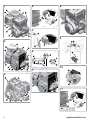 2
2
-
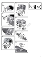 3
3
-
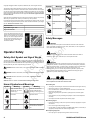 4
4
-
 5
5
-
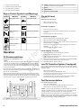 6
6
-
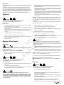 7
7
-
 8
8
-
 9
9
-
 10
10
-
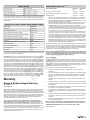 11
11
-
 12
12
-
 13
13
-
 14
14
-
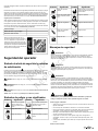 15
15
-
 16
16
-
 17
17
-
 18
18
-
 19
19
-
 20
20
-
 21
21
-
 22
22
-
 23
23
-
 24
24
-
 25
25
-
 26
26
-
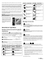 27
27
-
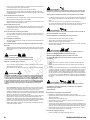 28
28
-
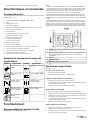 29
29
-
 30
30
-
 31
31
-
 32
32
-
 33
33
-
 34
34
-
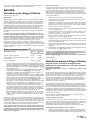 35
35
-
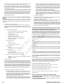 36
36
-
 37
37
-
 38
38
-
 39
39
-
 40
40


Simplicity 120202-0128-B8 Manuel utilisateur
- Catégorie
- Accessoires pour véhicules automobiles
- Taper
- Manuel utilisateur