Blomberg BCHP30100SS Manuel utilisateur
- Catégorie
- Hottes
- Taper
- Manuel utilisateur
Ce manuel convient également à

www.blomberginternational.com
Range Hood
User manual
Hotte
Manuel d’utilisation
Campana
Manual del usuario
BCHP30100SS
Document number : 01M-8851233200-0316-04

Ths product has been manufactured n envronmental frendly modern plants wthout gvng any harm to the nature.
Please read this manual first!
Dear Customers!
Thank you for preferring a Blomberg product. We hope that you get the best results
from your product which has been manufactured with high quality and state-of-the-art
technology. Therefore, please read this entire user manual and all other accompanying
documents carefully before using the product and keep it as a reference for future use.
If you handover the product to someone else, give the user manual as well. Follow all
warnings and information in the user manual.
Remember that this user manual is also applicable for several other models. Differences
between the models are explicitly described in the manual.
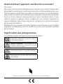
Meanings of the Symbols
Following symbols are used in the various section of this manual:
C
Important information and useful hints about
usage.
A
WARNING:
Warnings for dangerous situa-
tions concerning the safety of life and property.
B
Warning for electric shock.
Warning for hot surfaces.

Range Hood / User Manual
3 / 62 EN
CONTENTS
1 Important safety and
envronmental nstructons 4
1.1 General safety . . . . . . . . . . . . . . . . . . . . . . . . . . . . . . 4
1.1.1 Electrcal safety. . . . . . . . . . . . . . . . . . . . . . . . . . . 4
1.1.2 Product safety. . . . . . . . . . . . . . . . . . . . . . . . . . . . 5
1.1.3 Chldren's safety . . . . . . . . . . . . . . . . . . . . . . . . . . 6
1.2 Intended use . . . . . . . . . . . . . . . . . . . . . . . . . . . . . . . 6
1.3 Complance wth WEEE Drectve and
dsposng of the waste product. . . . . . . . . . . . . . . . .7
Complance wth RoHS Drectve: . . . . . . . . . . . . . . .7
1.4 Package nformaton . . . . . . . . . . . . . . . . . . . . . . . .7
2 Electrcal & Installaton
requrements 8
2.1 Electrcal requrements. . . . . . . . . . . . . . . . . . . . . 8
2.2 Before nstallng the hood . . . . . . . . . . . . . . . . . 8
3 Techncal specfıcatons of your
applance 9
3.1 Lst of Materals . . . . . . . . . . . . . . . . . . . . . . . . . . . . 9
3.1.1 Parts suppled . . . . . . . . . . . . . . . . . . . . . . . . . . . . 9
3.1.2 Parts not suppled . . . . . . . . . . . . . . . . . . . . . . . . 9
3.2 Dmensons and Clearances . . . . . . . . . . . . . . . 10
3.3 Ductng Optons and Examples. . . . . . . . . . . . 10
3.3.1 Ventng methods. . . . . . . . . . . . . . . . . . . . . . . . 10
3.4 Preparaton . . . . . . . . . . . . . . . . . . . . . . . . . . . . . . . 10
4 Installng your applance 12
4.1 Installaton - Ductng verson. . . . . . . . . . . . . . 12
4.2 İnstall hood onto wall . . . . . . . . . . . . . . . . . . . . . 12
4.2.1 Install Transton Onto Top of Hood. . . . . 12
4.2.2 Hang hood on wood support. . . . . . . . . . . . 13
4.2.3 Install bottom mountng screws . . . . . . . . 13
4.3 İnstall hood celng or beneath cabnets . . 13
4.3.1 Install Transton Onto Top of Hood. . . . . 14
4.3 2 Mount hood onto celng or cabnet . . . . . 14
4.3.3 Connectng the ductwork . . . . . . . . . . . . . . . 15
4.3.4 Electrcal connecton. . . . . . . . . . . . . . . . . . . . 15
4.3.5 Install Motor. . . . . . . . . . . . . . . . . . . . . . . . . . . . . 15
5 Operatng your applance 17
5.1 Descrpton of the hood & Controls . . . . . . . 17
5.1.1 Controls. . . . . . . . . . . . . . . . . . . . . . . . . . . . . . . . . . 17
5.1.2 Descrpton of control panel. . . . . . . . . . . . . 17
6 Cleanng and mantenance 18
6.1 Mantenance . . . . . . . . . . . . . . . . . . . . . . . . . . . . . . 18
6.2 Cleanng. . . . . . . . . . . . . . . . . . . . . . . . . . . . . . . . . . . 18
6.3 Grease Flter . . . . . . . . . . . . . . . . . . . . . . . . . . . . . . 18
6.3.1 Remove grease flters. . . . . . . . . . . . . . . . . . . 18
6.3.2 İnstall grease flters . . . . . . . . . . . . . . . . . . . . . 18
6.4 Replacng the lght bulb. . . . . . . . . . . . . . . . . . . 18
7 Warranty 20

4 / 62 EN
Range Hood / User Manual
1
Important safety and envronmental
nstructons
This section contains safety
instructions that will help protect
from risk of personal injury or
property damage. Failure to follow
these instructions invalidates the
granted warranty.
1.1 General safety
•Always have the installation and
repairing procedures carried out
by the Authorized Service Agent.
Manufacturing firm shall not be
held responsible for damages that
may be caused by unauthorized
persons.
•This appliance is not intended
for use by persons (including
children) with reduced physical,
sensory or mental capabilities, or
lack of experience and knowledge.
Children should be supervised to
ensure that they do not play with
the appliance.
1.1.1 Electrical safety
•Always unplug the appliance
from the mains supply during
installation, maintenance,
cleaning and repair operations.
•If the power cable is faulty,
it should be replaced by a
qualified person certified by
the manufacturer, after-sales
service or similar (preferably an
electrician) or a person described
by the importer.
•Operating voltage is 220 to 240
volts.
•If the appliance has a failure, it
should not be operated unless it is
repaired by the Authorized Service
Agent. There is the risk of electric
shock!
•Do not route power cable close
to hobs. Otherwise power cable
may cause fire since it melts down
easily.
•Never plug the hood before
installation is completed.
•In order to obtain the best
performance, external conductor
must not be longer than 4 m. It
must not contain more than 2
perpendicular (90°) angles and its
diameter must be min. ø120 mm.
•Disconnect the appliance from
mains before any intervention to
the internal parts of the appliance.
•Use the appliance with a grounded
outlet only.

Range Hood / User Manual
5 / 62 EN
1
Important safety and envronmental
nstructons
1.1.2 Product safety
•You can use a ppe wth a dameter
of 120 mm or 150 mm on the flue
connecton of the hood.
•Do not make connections to the
flues connected with stoves,
exhaust shafts or flues with rising
flames. Observe the rules set by
authorities on the discharge of
exhaust air.
•The height between the lower
surface of the hood and upper
surface of the stove/oven should
not be less than 50 cm for gas
hobs and 45 cm for electric hobs.
•Do not operate the hood without
aluminum filters and do not
remove the filters while it is
operated.
•Never touch the hood's lamps
after they are operated for a long
time. Hot lamps may burn your
hand.
•Avoid large flames beneath the
product. Otherwise, particles on
oil filter may ignite and lead to a
fire.
•Turn on the hobs after placing
pans or pots on it. Otherwise,
rising heat may deform certain
parts of your product.
•Turn off the hobs before taking
away pans or pots.
•Avoid inflammable materials under
the hood.
•Oil may ignite while frying foods.
Therefore, be careful about cloths
and curtains.
•Never leave the cooker unattended
when frying foods; otherwise hot
oil may cause fire.
•There is the risk of fire if your hood
is not cleaned in the specified
periods.
•Be extremely careful and wear
gloves when cleaning the hood.
•We advise you to operate the
appliance a few minutes before
starting to cook in order to
increase the suction power. Thus,
you shall have a continuous and
stable suction power when the
vapors arise.
•Operate your hood for 15 minutes
more after the end of cooking or
frying in order to remove the smell
and cooking vapor in the kitchen.
•When the hood is in use, especially
together with gas cookers,
make sure that environment is
ventilated with clean air.

6 / 62 EN
Range Hood / User Manual
•Pay attention not to connect
the appliance to the flues used
by non-electrical devices. (E.g.:
Heater flue).
•Simultaneous and smooth
operation of the hood and another
device that require air is only
possible when a low pressure
of 4 Pa (0.04 mbar) is reached,
and thus the reabsorption of the
gas is avoided. This can only be
achieved by means of air coming
from uncovered openings (door,
window, ventilation openings
or other technical measures).
Pay utmost attention to provide
sufficient air flow. A flue that
provides air ingress/egress is not
enough for this purpose.
1.1.3 Children's safety
•Packaging materials are dangerous
to children. Keep packaging
materials in a safe place out of
reach of children.
•Electrical appliances are
dangerous to children. Keep
children away from the product.
Do not allow children play with the
appliance.
•This appliance can be used by the
children who are at the age of 8 or
over and by the people who have
limited physical, sensory or mental
capacity or who do not have
knowledge and experience, as
long as they are supervised with
regard to safe use of the product
or they are instructed accordingly
and understand the risks of using
the product. Children should not
play with the appliance.
•
CAUTION:
Accessible parts may
heat up when used with a cooking
device.
1.2 Intended use
•This appliance is intended for
domestic use. It is not suitable for
commercial use and it must not be
used out of its intended use.
•The manufacturer shall not be
liable for any damage caused by
improper use or handling.
•Service life of your appliance is 10
years. This is the period required
for availability of spare parts for
proper functioning of the product.
1
Important safety and envronmental
nstructons

Range Hood / User Manual
7 / 62 EN
•
WARNING:
Failure to fix the
screws in concordance with
the instructions provided in the
manual may lead to electrical
hazards.
1.3 Compliance with WEEE
Directive and disposing of the
waste product
This product complies with EU WEEE
Directive (2012/19/EU). This product
bears a classification symbol for waste
electrical and electronic equipment
(WEEE).
This product has been manufactured with high
quality parts and materials which can be reused
and are suitable for recycling. Do not dispose of
the waste product with normal domestic and other
wastes at the end of its service life. Take it to the
collection center for the recycling of electrical and
electronic equipment. Please consult your local
authorities to learn about these collection centers.
Compliance with RoHS
Directive:
The product you have purchased complies with EU
RoHS Directive (2011/65/EU). It does not contain
harmful and prohibited materials specified in the
Directive.
1.4 Package information
Package of the product is made of
recyclable materials in accordance with
our National Legislation. Do not dispose
of the packaging materials together with the
domestic or other wastes. Take them to the
packaging material collection points designated by
the local authorities.
1
Important safety and envronmental
nstructons

8 / 62 EN
Range Hood / User Manual
2 Electrcal & Installaton requrements
2.1 Electrical requirements
C
Observe all governing codes and
ordinances.
It is the customer’s responsibility:
To contact a qualified electrical installer. To assure
that the electrical installation is adequate and in
conformance with National Electrical Code, ANSI/
NFPA 70 — latest edition*, or CSA Standards C22.1-
94, Canadian Electrical Code, Part 1 and C22.2
No.0-M91 - latest edition** and all local codes and
ordinances.
• If codes permit and a separate ground wire
is used, it is recommended that a qualified
electrician determine that the ground path is
adequate.
• Do not ground to a gas pipe.
• Check with a qualified electrician if you are not
sure range hood is properly grounded.
• Do not have a fuse in the neutral or ground
circuit.
C
Save Installation Instructions for
electrical inspector’s use.
C
The range hood must be connected
with copper wire only.
C
The range hood should be connected
directly to the fused disconnect (Or
circuit breaker) box through metal
electrical conduit.
Wire sizes must conform to the requirements of
the National Electrical Code ANSI/NFPA 70 — latest
edition*, or CSA Standards C22.1-94, Canadian
Electrical Code Part 1 and C22.2 No. 0-M91 - latest
edition** and all local codes and ordinances.
A U.L.- or C.S.A.-listed conduit connector must be
provided at each end of the power supply conduit
(at the range hood and at the junction box).
Copies of the standards listed may be obtained
from:
* National Fire Protection Association
Batterymarch Park Quincy, Massachusetts 02269
** CSA International 8501 East Pleasant Valley
Road Cleveland, Ohio 44131-5575
2.2 Before installing the hood
1. For the most efficient air flow exhaust, use a
straight run or as few elbows as possible.
A
WARNING:
Vent unit to outside
of building, only.
2. At least two people are necessary for
installation.
3. Fittings material is provided to secure the
hood to most types of walls/ceilings, consult
a Qualified Installer, check if they perfectly fit
with your cabinet/wall.
4. Do not use flex ducting.
5. COLD WEATHER installations should have an
additionalbackdraft damper installed to mini-
mize backward cold airflow and a nonmetallic
thermal break to minimizeconduction of out-
side temperatures as part of theductwork. The
damper should be on the cold air side ofthe
thermal break.The break should be as close as
possible to where theducting enters the heated
portion of the house.
6. Make up air: Local building codes may require the
use of Make-Up Air Systems when using Ducted
Ventilation Systems greater than specified CFM
of air movement. The specified CFM varies from
locale to locale. Consult your HVAC professional
for specific requirements in your area.
Removing the packaging
A
Remove carton carefully, Wear
gloves to protect against sharp
edges.
A
WARNING:
Remove the protec-
tive film covering the product before
putting into operation.

Range Hood / User Manual
9 / 62 EN
3 Techncal specfıcatons of your applance
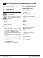
3.1 List of Materials
3.1.1 Parts supplied
Removing the packaging
A
Remove carton carefully, Wear
gloves to protect against sharp
edges.
A
WARNING:
Remove the protec-
tive film covering the product before
putting into operation.
• Hood canopy.
• Blower.
• Duct transition.
• Lamp already installed.
• Grease filter.
• Hardware bag with:
– Use, care and installation guide
– 2 hollow wall anchors with screws to secure
hood to the wall at the bottom
– 4 Wood screws to secure the wood support
to the wall
– 4 Phillips head screws to secure the transition
to the hood outlet on the top
– 6 Phillips head screws to secure hood to the
wood support (2 secured to wood support)
– 1 Safety screw and lock washer to secure
the blower (screw is marked with red or blue
paint)
– 2 Flat washers for wall anchors
3.1.2 Parts not supplied
Optional Accessories
• Duct Cover
• Heat Lamps kit (2 IR 175W)
• Backsplash kit
Tools/Materials required
• Wire nuts
• Tape to mount template
• 8” rounded metal duct length to suit installation
• Measuring tape
• Pliers
• Gloves
• Knife
• Safety glasses
• Electric drill with 5/16” and 3/8” Bits
• Strain relief
• Spirit level
• Duct tape
• Screwdrivers:
– Phillips (Posidrive) # 2
– Torx # 2
• Wire cutter/stripper
• Masking tape
• Hammer
• Saw, jig saw or reciprocating saw
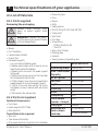
BCHP30100SS
Operatng mode
ducted out only
Max. Ventlaton
Capacty
515 CFM
Nr.of Speeds
4
Controls
Mechancal Knobs
Lghts
2 x 50 W Halogene
Flterng
2 x Baffle Flters
Volts
120 V
Frequency
60 Hz
Total Power
(motor + lamps)
550 W
Plug type
Hard Wre
Requred ds-
tance above
cooktop
30” (gas cooktop)
30” (electrcal cooktop)

10 / 62 EN
Range Hood / User Manual
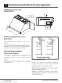
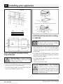
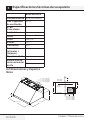
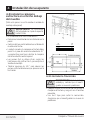
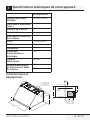
3.2 Dimensions and
Clearances
30”- 36”- 42“ - 48”
18”
25”
12”
6 - 1/2”
3 3/4”
18 - 1/16” Hotte de 48”
15 - 1/16” Hotte de 42”
12 - 1/16” Hotte de 36”
9 - 1/16” Hotte de 30”
CL
6”
8 -13/32”
18”
9 - 7/8””
CL
Top of Hood
Wood
Support
Bottom of Hood
House wiring
location
18 - 27/32” 48” Hood
15 - 27/32” 42” Hood
12 - 27/32” 36” Hood
9 - 27/32” 30” Hood
3.3 Ducting Options and
Examples
Closely follow the instructions set out in this
manual.
All responsibility, for any eventual inconveniences,
damages or fires caused by not complying with
the instructions in this manual, is declined.
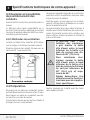
3.3.1 Venting methods
Vent Exhaust Option
The hood is equipped with a transition B for
discharge of fumes to the outside (Ducting
version).
Minimum Duct Size (Ducting/Ductless version):
10” Round Pipe.
3 Techncal specfıcatons of your applance
3.4 Preparation
Do not cut a joist or stud unless absolutely
necessary. If a joist or stud must be cut, then a
supporting frame must be constructed.
Fittings material is provided to secure the hood to
most types of walls/ceilings.
However, a qualified technician must verify
suitability of the materials in accordance with the
type of wall/ceiling.

Range Hood / User Manual
11 / 62 EN
3 Techncal specfıcatons of your applance
Before making cutouts, make sure there is proper
clearance within the ceiling or wall for exhaust
vent.
Hood installation height above cooktop is the
users preference. The lower the hood is above
the cooktop, the more efficient the capturing of
cooking odors, grease and smoke.
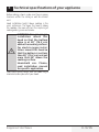
A
WARNING: For gas ranges
installation: mount this
hood so that the bottom
edge is at 30” (76,2 cm)
above the cooking surface.
For electric ranges instal-
lation: mount this hood so
that the bottom is not less
than 30” (76,2 cm) and not
more that 36” above the
cooking surface.
Household use. Please,
read installation manual
for specific application.
Check your ceiling height and the hood height
maximum before you select your hood.

12 / 62 EN
Range Hood / User Manual
4 Installng your applance
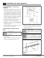
4.1 Installation - Ducting
version
• If possible, disconnect and move freestanding or
slide-in range from cabinet opening to provide
easier access to rear wall. Otherwise put a thick,
protective covering over countertop, cooktop or
range to protect from damage and debris. Select
a flat surface for assembling the unit. Cover that
surface with a protective covering and place all
canopy hood parts and hardware in it.
• Determine and mark the centerline on the wall
where the canopy hood will be installed.
• Select a mounting height comfortable for the
user and mark on wall.
• Tape template, matching center-line and hood
bottom.
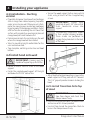
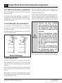
4.2 İnstall hood onto wall
A
IMPORTANT:
Framing must be
capable of supporting up to 150 lbs.
• Locate at least.2 vertical studs at the wood
support.
• Center the supplied wood support, left to right
and below the 15 3/8” marked line.
30”
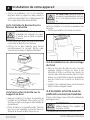
• Secure the wood support to 2 or more vertical
studs, using at least 2 of the 4 supplied long
screws.
A
IMPORTANT:
Screws must
penetrate at least 1 1/2” into vertical
studs. Countersink screws into
support.
C
The mounting screws must remain
in their original shipping location.
These screws are positioned to
engage the keyhole slots in the back
of the hood.
• Adjust depth of original mounting srcrews in the
wood support until they protrude 1/4” forward.
This 1/4” gap will provide clearance to hang the
hood.
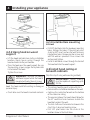
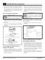
4.2.1 Install Transition Onto Top
of Hood
A
IMPORTANT:
Remove shipping
tape from damper and check that
damper moves freely.
• Place the transition piece over the hood exhaust
and secure with 4 screws provided.
• Use duct tape to seal the connection. Check to
be sure the damper moves freely.

Range Hood / User Manual
13 / 62 EN
4 Installng your applance
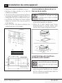
4.2.2 Hang hood on wood
support
• Lift the hood and hold close to the installation
location. Route house wiring through the
knockout and into the junction box.
• Place the hood over the wood support. Be sure
the mounting screws engage the keyhole slots
in the back of the hood.
Tighten the screws.
A
WARNING:
Continue to provide
additional support while the hood is
mounted with only these 2 screws.
These screws will not support the weight of the
hood. The hood could fall resulting in damage or
personal injury.
• Check to be sure the hood is level and centered.
30”
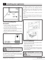
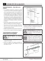
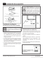
4.2.3 Install bottom mounting
screws
• Drill 1/8” pilot holes into the two lower mounting
holes. Enlarge the holes if they did not enter
studs to 3/8”. Insert anchors for wall fasteners
into bottom holes. Remove anchor screws and
add flat washers provided. Drive screws into
anchors and tighten.
• Install 4 additional screws through the back of
the hood and into the wood support.
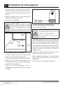
4.3 İnstall hood ceiling or
beneath cabinets
(Skip this step if using wall mounting method)
A
IMPORTANT:
Ceiling framing
must be capable of supporting up to
150 lbs.
• The ceiling should be constructed with 2x4’s.
• Determine the installation location on the wall.
• Continue the centerline forward on the bottom
of the cabinet or ceiling.
• The opening above the hood should allow for
the 10” round duct and clearance to slide the
hood back against the wall.
• The 2x4 studs must be located as shown in the
chart, Dim. A to accept monting screw.
• Drill 1/8” pilot holes into the studs at the
locations show in the illustration.

14 / 62 EN
Range Hood / User Manual
4 Installng your applance
23 9/16 “ 48”
20 9/16” 42”
17 9/16 36”
14 9/16” 30”
4.3.1 Install Transition Onto
Top of Hood
A
IMPORTANT:
Remove shipping
tape from damper and check that
damper moves freely.
• Place the transition piece over the hood exhaust
and secure with 4 screws provided.
• Use duct tape to seal the connection. Check to
be sure the damper moves freely.
4.3 2 Mount hood onto ceiling
or cabinet
C
If mounting to the underside of a
cabinet with a recessed bottom,
install shims to fill the gap.
• Drive mounting screws into the studs until
they protrude 1/4”. The 1/4” gap will provide
clearance to engage the keyhole slots in the top
of the hood.
• Lift hood to installation position. Locate house
wiring and route trough the knockout (from the
back or top of the hood).
• Lift hood onto mounting screws. Slide back
against the rear wall.
• Tighten mounting screws.
A
IMPORTANT:
For additional
support and to minimize vibration
during operation, the hood must be
secured to the back wall. Use wall
anchors to fasten bottom back of
hood to the wall.

Range Hood / User Manual
15 / 62 EN
4 Installng your applance
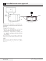
4.3.3 Connecting the
ductwork
• Install ductwork, making connections in the
direction of airflow as illustrated.
• Push duct over the exhaust outlet.
• Wrap all duct joints and the flange connections
with duct tape for an airtight seal.
• Make the same connection in the wall or ceiling
vent exit.
4.3.4 Electrical connection
Electrical Shock Hazard
B
Turn off power circuit at the service
panel before wiring this unit. 120
VAC, 15 or 20 Amp circuit required.
Electrical grounding instructions
This appliance is fitted with an electrical junction
box with 3 wires, one of which (green/yellow)
serves to ground the appliance.
To protect you against electric shock, the green
and yellow wire must be connected to the
grounding wire in your home electrical system,
and it must under no circumstances be cut or
removed.
Failure to do so can result in death or electrical
shock.
Remove the knockout and the Junction box cover
and install the conduit connector (cULus listed) in
junction box.
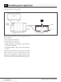
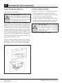
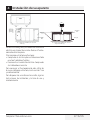
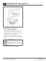
4.3.5 Install Motor
• From the inside of the hood, slip motor into the
attachment slot on the left.
• Rotate motor upwards until it snaps into the
spring clip on the right.
• Secure the motor to the hood with the machine
screw and lock washer. (Screw is marked with
red or blue paint).
A
IMPORTANT:
Connector ends
are designed to mate only one way.
Match flat and round connectors as
shown.

16 / 62 EN
Range Hood / User Manual
4 Installng your applance
• Plug connector into the motor.
Spring clip
Attachment
screw
Fig. 1: Single motor installation (30” range hood
model only)
Fig. 2: Double motor installation (36”, 42” & 48”
range hood models only)
Install the grease filter and turn power on at
service panel.
Check operation of the hood.
If range hood does not operate:
• Check that the circuit breaker is not tripped or
the house fuse blown.
• Disconnect power supply. Check that wiring is
correct.
To get the most efficient use from your new range
hood, read the “Use and Care Information” section.
Keep your Installation Instructions and Use and
Care Guide close to range hood for easy reference.

Range Hood / User Manual
17 / 62 EN
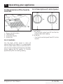
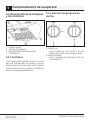
5 Operatng your applance
5.1 Description of the hood &
Controls
1. Blower and light controls
2. Lamp housings
3. Grease filter Handle
4. Grease filter
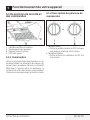
5.1.1 Controls
Use the high suction speed in cases of
concentrated kitchen vapours. It is recommended
that the cooker hood suction is switched on for 5
minutes prior to cooking and to leave in operation
during cooking and for another 15 minutes
approximately after terminating cooking.
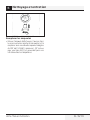
5.1.2 Description of control panel
1. Light Control
– Turn the light control from OFF to HI for the
brightest light while cooking.
2. Fan Control
– Turn the fan control speed from OFF to HI as
needed.

18 / 62 EN
Range Hood / User Manual
6 Cleanng and mantenance
6.1 Maintenance
C
Before performing any maintenance
operation, isolate the hood from the
electrical supply by switching off
at the connector and removing the
connector fuse.
Or if the appliance has been con-
nected through a plug and socket,
then the plug must be removed from
the socket.
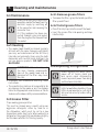
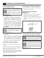
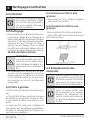
6.2 Cleaning
• The cooker hood should be cleaned regularly
(at least with the same frequency with which
you carry out maintenance of the fat filters)
internally and externally. Clean using the cloth
dampened with neutral liquid detergent. Do
not use abrasive products.
DO NOT USE
ALCOHOL!
A
WARNING:
Failure to carry out
the basic cleaning recommenda-
tions of the cooker hood and re-
placement of the filters may cause
fire risks.
• Therefore, we recommend oserving these
instructions.
• The manufacturer declines all responsibility for
any damage to the motor or any fire damage
linked to inappropriate maintenance or failure
to observe the above safety recommendations.
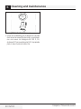
6.3 Grease Filter
Traps cooking grease particles.
This must be cleaned once a month using non
aggressive detergents, either by hand or in
the dishwasher, which must be set to a low
temperature and a short cycle. When washed in a
dishwasher, the grease filter may discolour slightly,
but this does not affect its filtering capacity.
6.3.1 Remove grease filters
• To remove the filters, grasp the handle, push the
filter up and lift out.
6.3.2 İnstall grease filters
• Place filter drip trays into the rear of the hood.
• Insert the grease filter into opening and drop
into the trays.
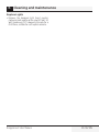
6.4 Replacing the light bulb
C
Before replacing the lamps, switch
power off at service panel and
lock service panel disconnecting
means to prevent power from being
switched on accidentally.
C
Turn off the lights and fan. Allow the
lights to cool before handling. If new
lights do not operate be sure lights
are inserted correctly before calling
service.

Range Hood / User Manual
19 / 62 EN
6 Cleanng and mantenance
Replace Lights
• Remove the damaged light (twist counter
clockwise) and replace with a new 120 Volt, 50
Watt (maximum) 50° halogen light made for a
GU10 base, suitable for use in open luminarie.

20 / 62 EN
Range Hood / User Manual
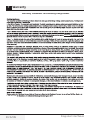
7 Warranty
Warranty Statement For Blomberg Range Hoods
1 800 459 9848
otherwise
La page est en cours de chargement...
La page est en cours de chargement...
La page est en cours de chargement...
La page est en cours de chargement...
La page est en cours de chargement...
La page est en cours de chargement...
La page est en cours de chargement...
La page est en cours de chargement...
La page est en cours de chargement...
La page est en cours de chargement...
La page est en cours de chargement...
La page est en cours de chargement...
La page est en cours de chargement...
La page est en cours de chargement...
La page est en cours de chargement...
La page est en cours de chargement...
La page est en cours de chargement...
La page est en cours de chargement...
La page est en cours de chargement...
La page est en cours de chargement...
La page est en cours de chargement...
La page est en cours de chargement...
La page est en cours de chargement...
La page est en cours de chargement...
La page est en cours de chargement...
La page est en cours de chargement...
La page est en cours de chargement...
La page est en cours de chargement...
La page est en cours de chargement...
La page est en cours de chargement...
La page est en cours de chargement...
La page est en cours de chargement...
La page est en cours de chargement...
La page est en cours de chargement...
La page est en cours de chargement...
La page est en cours de chargement...
La page est en cours de chargement...
La page est en cours de chargement...
La page est en cours de chargement...
La page est en cours de chargement...
La page est en cours de chargement...
La page est en cours de chargement...
La page est en cours de chargement...
La page est en cours de chargement...
-
 1
1
-
 2
2
-
 3
3
-
 4
4
-
 5
5
-
 6
6
-
 7
7
-
 8
8
-
 9
9
-
 10
10
-
 11
11
-
 12
12
-
 13
13
-
 14
14
-
 15
15
-
 16
16
-
 17
17
-
 18
18
-
 19
19
-
 20
20
-
 21
21
-
 22
22
-
 23
23
-
 24
24
-
 25
25
-
 26
26
-
 27
27
-
 28
28
-
 29
29
-
 30
30
-
 31
31
-
 32
32
-
 33
33
-
 34
34
-
 35
35
-
 36
36
-
 37
37
-
 38
38
-
 39
39
-
 40
40
-
 41
41
-
 42
42
-
 43
43
-
 44
44
-
 45
45
-
 46
46
-
 47
47
-
 48
48
-
 49
49
-
 50
50
-
 51
51
-
 52
52
-
 53
53
-
 54
54
-
 55
55
-
 56
56
-
 57
57
-
 58
58
-
 59
59
-
 60
60
-
 61
61
-
 62
62
-
 63
63
-
 64
64


Blomberg BCHP30100SS Manuel utilisateur
- Catégorie
- Hottes
- Taper
- Manuel utilisateur
- Ce manuel convient également à
dans d''autres langues
- English: Blomberg BCHP30100SS User manual
- español: Blomberg BCHP30100SS Manual de usuario