
GLS-LDL-EX-BATT
Battery-Powered Photosensor, Dual-Loop
Installation & Operation Guide
Description
The Crestron
®
GLS-LDL-EX-BATT is a battery-powered, wireless photosensor designed
for daylight harvesting applications to control the balance of natural and articial lighting
in an indoor space. Dual-loop sensing is achieved on the GLS-LDL-EX-BATT by two
internal photocells—one for open-loop daylight sensing and one for closed-loop ambient
light sensing.
The GLS-LDL-EX-BATT has a micro-USB port that provides a direct connection to a PC
running Crestron Toolbox™ software.
Additional Resources
Visit the product page on the Crestron website (www.crestron.com)
for additional information and the latest rmware updates. Use a QR
reader application on your mobile device to scan the QR image.
inNET EX logo only needed for inNET
EX products. The mere mention of
inNET EX in a document is not cause to
use the logo.
Installation
NOTES: Observe the following points:
• Install and use this product in accordance with appropriate electrical codes and
regulations.
• A licensed electrician should install this product.
• Mount sensors on a vibration-free surface.
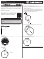
The GLS-LDL-EX-BATT must be installed so that it faces a window. The device should
be installed approximately 4 to 6 feet (1.22 to 1.83 meters) away from the window. The
optimum viewing angle for the open loop sensor is 35˚. The closed-loop viewing angle is
straight down.
Arrow must point
toward window.
Holes for mounting
screws.
Mount the Base
When mounting the base, ensure that the arrow on the base, shown below, points toward
the desired window.
35°
Insert the Batteries
Insert the batteries into the back of the GLS-LDL-EX-BATT. The orientation of the batteries
is indicated on the device.
Mount the base to drywall or a drop ceiling using the provided anchors.
1. Determine the proper orientation for the GLS-LDL-EX-BATT.
2. Hold the base on the mounting surface, and use the holes for the mounting screws
to mark the screw locations.
3. Using a 1/4-inch drill bit, drill a pilot hole for the small anchor, and then insert the
small anchor into the pilot hole.
4. Using a #2 or #3 Phillips screwdriver, push the self-tapping anchor into the surface
of the drywall until the cutting blades penetrate the surface. Using gentle forward
pressure, rotate the anchor until the collar sets ush to the surface of the ceiling.
5. Secure the base to the mounting surface using two screws.
6. Place the sensor on the base and then rotate the sensor clockwise to secure it.
The sensor has the capability to rotate up to 40º along the base after it is mounted. Rotate
the sensor so that it is perpendicular to the window.
Conguration
The GLS-LDL-EX-BATT is set up and congured during system commissioning. Refer to
the help le for details.

As of the date of manufacture, the device has been tested and found to comply with specications for
CE marking.
Federal Communications Commission (FCC) Compliance Statement
This device complies with part 15 of the FCC Rules. Operation is subject to the following conditions:
(1) This device may not cause harmful interference and (2) this device must accept any interference
received, including interference that may cause undesired operation.
CAUTION: Changes or modications not expressly approved by the manufacturer responsible for
compliance could void the user’s authority to operate the equipment.
NOTE: This equipment has been tested and found to comply with the limits for a Class B digital
device, pursuant to part 15 of the FCC Rules. These limits are designed to provide reasonable
protection against harmful interference in a residential installation. This equipment generates, uses
and can radiate radio frequency energy and, if not installed and used in accordance with the
instructions, may cause harmful interference to radio communications. However, there is no guarantee
that interference will not occur in a particular installation. If this equipment does cause harmful
interference to radio or television reception, which can be determined by turning the equipment off
and on, the user is encouraged to try to correct the interference by one or more of the following
measures:
• Reorient or relocate the receiving antenna.
• Increase the separation between the equipment and receiver.
• Connect the equipment into an outlet on a circuit different from that to which the receiver is
connected.
• Consult the dealer or an experienced radio/TV technician for help.
Industry Canada (IC) Compliance Statement
This device complies with Industry Canada license-exempt RSS standard(s). Operation is subject to
the following two conditions: (1) this device may not cause interference and (2) this device must
accept any interference, including interference that may cause undesired operation of the device.
Under Industry Canada regulations, this radio transmitter may only operate using an antenna of a type
and maximum (or lesser) gain approved for the transmitter by Industry Canada. To reduce potential
radio interference to other users, the antenna type and its gain should be so chosen that the
equivalent isotropically radiated power (e.i.r.p.) is not more than that necessary for successful
communication.
Industrie Canada (IC) Déclaration de conformité
Le présent appareil est conforme aux CNR d'Industrie Canada applicables aux appareils radio
exempts de licence. L'exploitation est autorisée aux deux conditions suivantes: (1) l'appareil ne doit
pas produire de brouillage, et (2) l'utilisateur de l'appareil doit accepter tout brouillage radioélectrique
subi, même si le brouillage est susceptible d'en compromettre le fonctionnement.
Conformément à la réglementation d'Industrie Canada, le présent émetteur radio peut fonctionner
avec une antenne d'un type et d'un gain maximal (ou inférieur) approuvé pour l'émetteur par Industrie
Canada. Dans le but de réduire les risques de brouillage radioélectrique à l'intention des autres
utilisateurs, il faut choisir le type d'antenne et son gain de sorte que la puissance isotrope rayonnée
équivalente (p.i.r.e.) ne dépasse pas l'intensité nécessaire à l'établissement d'une communication
satisfaisante.
To satisfy RF exposure requirements, this device and its antenna must operate with a separation
distance of at least 20 centimeters from all persons and must not be colocated or operating in
conjunction with any other antenna or transmitter.
The product warranty can be found at www.crestron.com/warranty.
The specic patents that cover Crestron products are listed at patents.crestron.com.
Crestron, the Crestron logo, Crestron Toolbox, inNET EX, and the inNET EX logo are either
trademarks or registered trademarks of Crestron Electronics, Inc. in the United States and/or other
countries. Energizer is a trademark or registered trademark of Energizer Battery Company, Inc. Other
trademarks, registered trademarks, and trade names may be used in this document to refer to either
the entities claiming the marks and names or their products. Crestron disclaims any proprietary
interest in the marks and names of others. Crestron is not responsible for errors in typography or
photography.
This document was written by the Technical Publications department at Crestron.
©2017 Crestron Electronics, Inc.
Crestron Electronics, Inc. Installation & Operation Guide - DOC. 7554B
15 Volvo Drive Rockleigh, NJ 07647 (2043706)
Tel: 888.CRESTRON 04.17
Fax: 201.767.7576 Specications subject to
www.crestron.com change without notice.
Replace the Batteries
The battery should be replaced with a battery that is the same or better than the provided
Energizer
®
L92 Ultimate Litium AAA battery. Discard batteries appropiately after use.
RF ID
It is recommended to have direct access to the GLS-LDL-EX-BATT and to use Crestron
Toolbox to set the RF ID of the device. Set the RF ID for the GLS-LDL-EX-BATT by doing
the following.
1. Wake the device by pressing the button on the GLS-LDL-EX-BATT.
2. Set the RF ID of the device using Crestron Toolbox. The RF ID must match the RF ID
specied in the Crestron Studio or SIMPL Windows program.
3. Press the button on the GLS-LDL-EX-BATT to ensure that the device is still awake
and the RF ID is transferred to the device.
The RF ID can also be set by putting the device into Setup mode.
1. Press the button for more than 4 seconds. The LEDs blink.
2. Set the RF ID using Crestron Toolbox. Setup mode exits after 5 minutes.
Firmware Upgrade
NOTE: Before using the GLS-LDL-EX-BATT, ensure the device is using the latest
rmware. Check for the latest rmware for the GLS-LDL-EX-BATT at
www.crestron.com/rmware. Firmware is loaded onto the device using Crestron
Toolbox.
NOTE: To load rmware onto the GLS-LDL-EX-BATT prior to installation, use a PC
running Crestron Toolbox software that is connected to the GLS-LDL-EX-BATT using a
USB cable.
NOTE: Only one over-the-air rmware upgrade can be performed at a time.
To upgrade the rmware on the GLS-LDL-EX-BATT, follow the procedure below using
Crestron Toolbox (v. 2.36.216 or later):
1. Select Tools > Network Device Tree View.
2. Right-click the GLS-LDL-EX-BATT in the Network Device Tree View window.
3. Select Functions > Firmware Upload.
4. Click the Browse button in the Firmware Upload window and browse for the
rmware in the Open window.
5. Click the Send button to transfer the rmware.
NOTE: The rmware temporarily stays on the gateway until the
GLS-LDL-EX-BATT initiates the rmware transfer.
6. Initiate the rmware transfer by pressing the button on the GLS-LDL-EX-BATT,
waiting 5 seconds, and then pressing the button again.
NOTE: The LED on the GLS-LDL-EX-BATT blinks once every 1.5 seconds to
indicate that the rmware is being transferred to the device. If the LED does not
start blinking, repeat step 6.
7. Refresh the Network Device Tree View window to conrm that the rmware was
transferred.
Wireless Communications
The device connects to the Crestron network via the inNET EX
®
communications
protocol. Use the procedures outlined below to join or leave an inNET EX network and to
verify communications between the device and the control system.
Joining an inNET EX Network
Before a device can be used in a lighting system, it must rst join an inNET EX network.
To join an inNET EX network, the device must be acquired by an inNET EX gateway.
NOTE: A device can be acquired by only one gateway.
1. Put the inNET EX gateway into Acquire mode from the unit itself or from Crestron
Toolbox. Refer to the gateway’s manual at www.crestron.com/manuals for details.
NOTE: In an environment where multiple gateways are installed, only one
gateway should be in Acquire mode at any time.
2. Put the device into Acquire mode by doing the following:
a. Tap the button three times and then press and hold it down
(tap-tap-tap-press+hold) until the top LEDs on the device blink once (this can take
up to 10 seconds).
b. Release the button to start the acquire process. The LED blinks slowly to show
that the device is actively scanning the inNET EX network.
• The LED turns on for 5 seconds to show that the device has been successfully
acquired by the infiNET EX network.
• The LED blinks fast to indicate that the device was not successfully acquired
by the infiNET EX network. Tap the top button to acknowledge the failure. The
LEDs time out automatically. Ensure the gateway is in Acquire mode and
within range before attempting the acquire process again.
Leaving an inNET EX Network
To leave an inNET EX network, put the device into Acquire mode, as described in
“Joining an inNET EX Network” above, when no gateway is in Acquire mode.
Verifying Communications Status
To check the communication status of the device, tap the button three times and then
press and hold it down (tap-tap-tap-press+hold) for up to 2 seconds. The LED blinks to
indicate the communications status. Refer to the following table for details.
NOTE: Wireless networks composed predominantly of battery-powered devices may
need additional infiNET EX expanders, such as the CLW-EXPEX or GLA-EXPEX (sold
separately) or other non-battery powered infiNET EX devices, to ensure proper
functionality of the network and battery life for the devices. Refer to the Best Practices for
Installation and Setup of Crestron RF Products (Doc. 6689) at
www.crestron.com/manuals for complete system design guidelines or contact Crestron
True Blue Support for further assistance.
LED COMMUNICATIONS STATUS
Blinks three times The device is communicating with the gateway.
Blinks twice The device was previously joined to the network but is
not communicating with the gateway.
Blinks once The device is not joined to the network.
-
 1
1
-
 2
2


dans d''autres langues
- English: Crestron GLS-LDL-EX-BATT User guide
Documents connexes
-
Crestron CLW-EXPEX Guide d'installation
-
-
-
-
-
-
-
-
-