
Models
HR24B
Undercounter Refrigerator
Service Manual
Number: 73229
Issued: 3-6-2019
hoshizakiamerica.com

2
WARNING
Only qualied service technicians should install and service the appliance. To
obtain the name and phone number of your local Hoshizaki Certied Service
Representative, visit www.hoshizaki.com. No service should be undertaken until
the technician has thoroughly read this Service Manual. Failure to service and
maintain the appliance in accordance with this manual will adversely affect safety,
performance, component life, and warranty coverage. Proper installation is the
responsibility of the installer. Product failure or property damage due to improper
installation is not covered under warranty.
Hoshizaki provides this manual primarily to assist qualied service technicians in the
service of this appliance.
Should the reader have any questions or concerns which have not been satisfactorily
addressed, please call, send an e-mail message, or write to the Hoshizaki Technical
Support Department for assistance.
Phone: 1-800-233-1940; (770) 487-2331
Fax: 1-800-843-1056; (770) 487-3360
E-mail: techsuppor[email protected]
618 Highway 74 South
Peachtree City, GA 30269
Attn: Hoshizaki Technical Support Department
Web Site: www.hoshizaki.com
NOTE: To expedite assistance, all correspondence/communication MUST include the
following information:
• Model Number
• Serial Number
• Complete and detailed explanation of the problem.

3
CONTENTS
Important Safety Information ................................................................................................. 4
I. General Information ............................................................................................................ 7
A. Construction .................................................................................................................. 7
1. HR24B...................................................................................................................... 7
2. Dimensions and Storage Capacity .......................................................................... 8
B. Refrigeration Circuit....................................................................................................... 9
II. Sequence of Operation and Service Diagnosis ............................................................... 10
A. Sequence of Operation Flow Chart ............................................................................. 10
B. Cabinet Temperature and Defrost ................................................................................11
C. Display Module Icons .................................................................................................. 12
D. Control Panel Lockout ................................................................................................. 12
E. Service Diagnosis ....................................................................................................... 13
F. Control Board and Display Module Check ................................................................... 17
1. Control Board Layout ............................................................................................. 17
2. Display Module Layout .......................................................................................... 17
3. Control Board Check ............................................................................................. 18
G. Thermistor Check ........................................................................................................ 19
H. Diagnostic Chart ......................................................................................................... 20
I. Alarm Safeties .............................................................................................................. 22
J. Service Menu ............................................................................................................... 23
III. Refrigeration Circuit and Component Service Information ............................................. 29
A. Refrigeration Circuit Service Information .................................................................... 31
B. Component Service Information .................................................................................. 34
C. Door Reversal ............................................................................................................. 34
IV. Cleaning and Maintenance Instructions .......................................................................... 35
A. Cleaning ...................................................................................................................... 35
B. Maintenance ................................................................................................................ 35
V. Preparing the Appliance for Periods of Non-Use ............................................................. 36
VI. Disposal .......................................................................................................................... 37
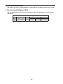
VII. Technical Information ..................................................................................................... 38
A. Electrical and Refrigerant Data ................................................................................... 38
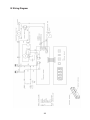
B. Wiring Diagram ............................................................................................................ 39
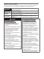
IMPORTANT
This manual should be read carefully before the appliance is serviced. Read
the warnings and guidelines contained in this booklet carefully as they provide
essential information for the continued safe use, service, and maintenance of the
appliance. Retain this booklet for any further reference that may be necessary.

4
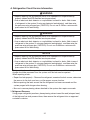
Important Safety Information
Throughout this manual, notices appear to bring your attention to situations which could
result in death, serious injury, damage to the appliance, or damage to property.
DANGER
Indicates a hazardous situation that, if not avoided, will result in
death or serious injury.
WARNING
Indicates a hazardous situation that, if not avoided, could result
in death or serious injury.
NOTICE
Indicates a situation that, if not avoided, could result in damage
to the appliance or property.
IMPORTANT
Indicates important information about the use and care of the
appliance.
DANGER
Risk of Fire or Explosion
Flammable Refrigerant Used
• Follow handling instructions carefully
in compliance with U.S. government
regulations.
• Do not use mechanical devices to defrost.
• Do not puncture refrigerant tubing. Risk
of re or explosion due to puncture
of refrigerant tubing; follow handling
instructions carefully.
• Component parts shall be replaced with
like components.
• Servicing shall be done by factory
authorized service personnel to minimize
the risk of possible ignition due to incorrect
parts or improper service.
• Consult instruction manual/ service
manual before attempting to install or
service this product. All safety precautions
must be followed.
• Dispose of properly in accordance with
federal or local regulations.
• Do not place any potential ignition sources
in or near the appliance.
Risque De Feu Ou D'Explosion
Le Frigorigène Est Inammable
• Suivre attentivement les instructions
de manipulation conformément à la
réglementation gouvernementale.
• Ne pas utiliser d'appareils mécaniques
pour dégivrer le réfrigérateur.
• Ne pas perforer la tubulure contenant le
frigorigène. Risque de feu ou d'explosion
si la tubulure contenant le frigorigène
est perforée; suivre les instructions de
manutention avec soin.
• Les pièces des composants doivent être
remplacées par des pièces et accessoires
équivalents.
• L’entretien doit être effectué par le
personnel de service autorisé par le
fabricant an de minimiser les risques
d’inammation attribuables à l’installation
d’une pièce inadéquate ou à la mauvaise
exécution du service.
• Consulter le manuel du propriétaire/
guide de réparation avant de tenter une
réparation. Toutes les mesures de sécurité
doivent être respectées.
• Éliminer conformément aux règlements
fédéraux ou locaux.
• Ne placez aucune source d’inammation
potentielle dans ou près de l’appareil.

5
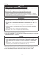
WARNING
The appliance should be destined only to
the use for which it has been expressly
conceived. Any other use should be
considered improper and therefore
dangerous. The manufacturer cannot be
held responsible for injury or damage
resulting from improper, incorrect, and
unreasonable use. Failure to install,
operate, and maintain the appliance
in accordance with this manual will
adversely affect safety, performance,
component life, and warranty coverage.
To reduce the risk of death, electric
shock, serious injury, or re, follow
basic precautions including the
following:
• Only qualied service technicians should
install and service the appliance.
• Wear appropriate personal protective
equipment (PPE) when servicing the
appliance.
• The appliance must be installed in
accordance with applicable national, state,
and local codes and regulations.
• Appliance is heavy. Use care when lifting
or positioning. Work in pairs when needed
to prevent injury or damage. Do not lift
using the top section or the door.
• To reduce the risk of electric shock, do not
touch the plug with damp hands.
• Unplug the appliance before servicing.
• The appliance requires an independent
power supply of proper capacity. See the
nameplate for electrical specications.
Failure to use an independent power
supply of proper capacity can result in a
tripped breaker, blown fuse, damage to
existing wiring, or component failure. This
could lead to heat generation or re.
• THE APPLIANCE MUST BE
GROUNDED. The appliance is equipped
with a NEMA5-15 three-prong grounding
plug to reduce the risk of potential
shock hazards. It must be plugged into a
properly grounded, independent 3-prong
wall outlet. If the outlet is a 2-prong outlet,
it is your personal responsibility to have
a qualied electrician replace it with a
properly grounded, independent 3-prong
wall outlet. Do not remove the ground
prong from the power cord and do not use
an adapter plug. Failure to follow these
instructions may result in death, electric
shock, or re.
• Do not use an extension cord.
• Do not use an appliance with a damaged
power cord. The power cord should not be
altered, jerked, bundled, weighed down,
pinched, or tangled. Such actions could
result in electric shock or re. To unplug
the appliance, be sure to pull the plug, not
the cord, and do not jerk the cord.
• The GREEN ground wire in the factory-
installed power cord is connected to the
appliance. If it becomes necessary to
remove or replace the power cord, be
sure to connect the power cord's ground
wire.
• Do not splash, pour, or spray water
directly onto or into the appliance. This
might cause short circuit, electric shock,
corrosion, or failure.
• Do not make any alterations to the
appliance. Alterations could result in
electric shock, injury, re, or damage to
the appliance.
• The appliance is not intended for use by
persons (including children) with reduced
physical, sensory, or mental capabilities,
or lack of experience and knowledge,
unless they have been given supervision
or instruction concerning use of the
appliance by a person responsible for
their safety.

6
WARNING, continued
• Children should be properly supervised
around the appliance.
• Do not climb, stand, or hang on the
appliance or door or allow children or
animals to do so. Do not climb into the
appliance or allow children or animals to
do so. Death or serious injury could occur
or the appliance could be damaged.
• Be careful not to pinch ngers when
opening and closing the door. Be careful
when opening and closing the door when
children are in the area.
• Open and close the door with care.
Opening the door too quickly or forcefully
may cause injury or damage to the
appliance or surrounding equipment.
• Do not use combustible spray or place
volatile or ammable substances in or
near the appliance. They might catch re.
• Keep the area around the appliance clean.
Dirt, dust, or insects in the appliance
could cause harm to individuals or
damage to the equipment.
• Do not block air inlets or outlets, otherwise
cooling performance may be reduced.
• Do not tightly pack the cabinet. Allow
some space between items to ensure
good air ow. Also allow space between
items and interior surfaces.
NOTICE
• Protect the oor when moving the
appliance to prevent damage to the oor.
• Keep ventilation openings, in the
appliance enclosure or in the built-in
structure, clear of obstruction. Do not
place anything on top of the appliance in
an undercounter installation. There must
be at least 1.5" (4 cm) overhead clearance
for proper ventilation. The factory-installed
rear bumpers must be in place to ensure
proper rear clearance. Blockage of airow
could negatively affect performance and
damage the appliance.
• Do not tightly pack the cabinet. Allow
some space between items to ensure
good air ow. Also allow space between
items and interior surfaces.
• Do not store items near the air outlet. They
might freeze up and crack or break.
• To prevent deformation or cracks, do not
spray insecticide onto the plastic parts or
let them come into contact with oil.
• To avoid damage to the gasket, use
only the door handle when opening and
closing.

7
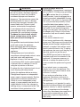
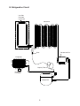
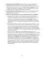
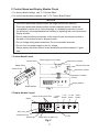
I. General Information
A. Construction
1. HR24B
Display Module/
Control Board
Condenser
Door
Door Gasket
Start Relay
Door Switch
Compressor
Condensate Drain
Pan
Power Cord
• Evaporator Fan
• Evaporator
• Cabinet Thermistor
• Evaporator Fan Shroud
Door Lock
Drier
Capillary Tube
Compressor
Wire Harness
Condensate
Drain Line
Wire Shelves

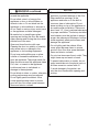
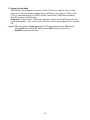
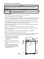
8
20
[ 3/4 ]
24
[ 1 ]
50
[ 2 ]
460
[ 18 - 1/8 ]
487
[ 19 - 1/8 ]
609
[ 24 ]
570
[ 22 - 1/2 ]
785
[ 30 - 7/8 ]
805
[ 31 - 3/4 ]
595
[ 23 - 3/8 ]
330
[ 13 ]
475
[ 18 - 3/4 ]
624
[ 24 - 5/8 ]
Unit: mm [in.]
Front View Side View
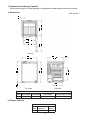
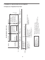
2. Dimensions and Storage Capacity
We reserve the right to make changes in specications and design without prior notice.
a) Dimensions
Additional Dimensions (mm [in.])
Model Interior Width Interior Height Interior Depth Door Stay Open Position
HR24B 460 [18 1/2] 475 [18 3/4] 450/330 [17 3/4 / 13] 616 [24 1/4]
b) Storage Capacity
Storage Capacity
Model
Interior Storage
Capacity (ft
3
)
Total Shelf
Space (ft
2
)
HR24B 3.67 2.26
Top View

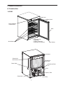
9
B. Refrigeration Circuit
Evaporator
Capillary Tube
Compressor
Drier
Condenser
Left Side
Perimeter
Liquid Line
Condensate Pan
Evaporator
Fan Motor

10
HR24B Sequence Flow Chart
• Defrost icon turns on.
• If Comp run time
<3min., Comp icon
and Comp continue
until 3-min. Comp run
timer terminates. Once
3-min. Comp run timer
terminates, Comp
de-energizes and defrost
starts.
Legend:
Comp-compressor
CTh-cabinet thermistor
ESM-energy saving mode
EvapFM-evaporator fan motor
DT-defrost timer
1. Startup
3. Cool Down Achieved
EvapFM continues
Comp energized
CTh in control
• CTh cools to setpoint.
Factory default is 39°F.
• 3-min. Comp run timer
terminates.
• 2-min. Comp off timer
starts.
4. Defrost
EvapFM continues
Comp de-energized
Note:
• EvapFM de-energizes when door is open.
• There is a Comp delay of 2 min. at startup.
• There is a minimum Comp run time of 3 min.
• There is a Comp delay of 2 min. after a power interruption.
• To initiate manual defrost, press and hold the "+" button until the
defrost icon turns on the display module.
• Defrost lasts 30 min.
Power on
EvapFM continues
Comp de-energized
EvapFM energized
3-min. Comp
run timer starts.
30-min. DT terminates
6-hr. DT starts
2. Cool Down
CTh 4°F
above setpoint
• 2-min. Comp delay.
• Comp icon ashes
during Comp delay.
CTh warms to 4°F
above setpoint
Energy Saving Mode
20-Min. ESM Timer Starts
EvapFM continues
Comp cycles on and off as
required by CTh
Setpoint
Achieved
• Door must remain
closed for 20min. after
setpoint achieved.
20-Min. ESM Timer Terminates
Comp cycles on and off as
required by CTh
EvapFM energizes on and off
with Comp cycle
EvapFM when Comp de-energized:
1 min. on, 5 min. off
• When Comp de-energized, EvapFM
operates 1 min. on, 5 min. off.
Door Switch activated (door open):
20-min. ESM Timer resets
EvapFM energizes
II. Sequence of Operation and Service Diagnosis
A. Sequence of Operation Flow Chart

11
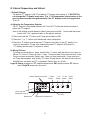
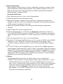
B. Cabinet Temperature and Defrost
1. Default Settings
The default CT setpoint is 39°F. The default CT display scale setting is °F. NOTICE! Do
not change the CT display scale from °Fto°C. All temperature related values in the
service menu must be changed manually if the CT display scale is changed from
°Fto °C.
a) Adjusting the Temperature Setpoint
The CT setpoint is adjustable between 34°F and 52°F. Follow the directions below to
adjust the CT setpoint.
Note: If the display module panel is locked, press and hold the "-" button and the power
button until "UnL" appears briey on the display module.
1) Press and hold the "P" button until Compicon ashes on DM.
2) Press the "-" or "+" button until the desired value is displayed.
3) Press the "P" button to save the new CT setpoint and return to the CT display. Ifno
button is pressed for 15 sec. after selecting the new CT setpoint, DM returns to
CTdisplay and the new CT setpoint is saved.
b) Manual Defrost
To initiate a manual defrost, press and hold the "+" button until the defrost icon turns on.
30-min.DTstarts. If Comp run time < 3 min., Comp icon and Comp continue until 3-min.
Comp run timer terminates. Once 3-min. Comp run timer terminates, Comp icon turns
off, Comp de-energizes, and 30-min. DT starts. During defrost, the defrost icon stays on,
EvapFM runs normally, and CT is displayed. Defrost lasts for 30min.
Legend: Comp–compressor; CT–cabinet temperature; DM–display module; DT–defrost
timer; EvapFM–evaporator fan motor
Compressor Icon
Defrost Icon
Evaporator Fan Motor Icon
Power
Button
"P" Set
Button
"+" Up
Button
"-" Down
Button
Alarm Icon
°C
°F
°F LED
Cabinet Temperature LEDs

12
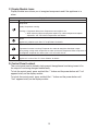
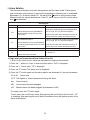
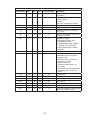
C. Display Module Icons
Display module icons inform you of energized components and if the appliance is in
alarm.
Display Module Icons
Icon Meaning
Compressor
Steady: Compressor running.
Flashing: • Compressor delay timer. Compressor starts within 2 min.
• While adjusting cabinet temperature setpoint. For cabinet temperature setpoint
adjustment, see "II.B Cabinet Temperature and Defrost."
Defrost
Appliance is in defrost cycle. See "II.F.3.10) Defrost" for details.
Evaporator Fan Motor
Evaporator fan motor is running. Evaporator fan motor de-energizes when door is open.
During energy saving mode, evaporator fan motor cycles with compressor. When compressor is
de-energized, evaporator fan motor cycles 1 min. on and 5 min. off.
Alarm
Appliance is in alarm. See "II.I. Alarm Safeties" for details.
D. Control Panel Lockout
The control panel can be locked to help prevent the appliance from being turned off or
the setpoint from being changed inadvertently.
To lock the control panel, press and hold the "-" button and the power button until "Loc"
appears briey on the display module.
To unlock the control panel, press and hold the "-" button and the power button until
"UnL" appears briey on the display module.

13
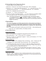
E. Service Diagnosis
DANGER
Risk of Fire or Explosion
Flammable Refrigerant Used
• Follow handling instructions carefully
in compliance with U.S. government
regulations.
• Do not use mechanical devices to defrost.
• Do not puncture refrigerant tubing. Risk
of re or explosion due to puncture
of refrigerant tubing; follow handling
instructions carefully.
• Component parts shall be replaced with
like components.
• Servicing shall be done by factory
authorized service personnel to minimize
the risk of possible ignition due to
incorrect parts or improper service.
• Consult instruction manual/service manual
before attempting to install or service this
product. All safety precautions must be
followed.
• Dispose of properly in accordance with
federal or local regulations.
• Do not place any potential ignition sources
in or near the appliance.
Risque De Feu Ou D'Explosion
Le Frigorigène Est Inammable
• Suivre attentivement les instructions
de manipulation conformément à la
réglementation gouvernementale.
• Ne pas utiliser d'appareils mécaniques
pour dégivrer le réfrigérateur.
• Ne pas perforer la tubulure contenant le
frigorigène. Risque de feu ou d'explosion
si la tubulure contenant le frigorigène
est perforée; suivre les instructions de
manutention avec soin.
• Les pièces des composants doivent être
remplacées par des pièces et accessoires
équivalents.
• L’entretien doit être effectué par le
personnel de service autorisé par le
fabricant an de minimiser les risques
d’inammation attribuables à l’installation
d’une pièce inadéquate ou à la mauvaise
exécution du service.
• Consulter le manuel du propriétaire/
guide de réparation avant de tenter une
réparation. Toutes les mesures de sécurité
doivent être respectées.
• Éliminer conformément aux règlements
fédéraux ou locaux.
• Ne placez aucune source d’inammation
potentielle dans ou près de l’appareil.
WARNING
• This appliance should be diagnosed and repaired only by qualied service
personnel to reduce the risk of death, electric shock, serious injury, or re.
• Wear appropriate personal protective equipment (PPE) when servicing the
appliance.
• Risk of electric shock. Use extreme caution and exercise safe electrical practices.
• Moving parts (e.g. fan blade) can crush and cut. Keep hands clear.
• Appliance is heavy. Use care when lifting or positioning. Work in pairs when
needed to prevent injury or damage.
• Make sure all food zones are clean after the appliance is serviced.

14
The diagnostic procedure is basically a sequence check that allows you to diagnose the
electrical system and components. Before proceeding, check for correct installation and
proper voltage per appliance nameplate. When checking AC voltage (115VAC), always
choose a neutral (W) wire to establish a good neutral connection. If the control board is
in alarm, see "II.I Alarm Safeties." For further details, see "II.F.3. Control Board Check."
• If the control panel is locked, press and hold the "-" button and the power button until
"UnL" appears briey on the display module.
• The °F and cabinet temperature LEDs remain on throughout the sequence of operation.
• This appliance uses a time-initiated/time-terminated Comp off cycle defrost. The factory
default defrost setting is once every 6 hours for 30min.
• 6-hr. defrost timer starts the very rst time CB is energized (during factory testing).
Defrost time is cumulative power on time, therefore time may vary between starting
the appliance and the rst defrost. After the rst defrost, defrost can be monitored for
activation every 6 hours.
• Cabinet temperature is displayed during defrost.
1) Press and hold the power button for 2 sec. to turn off the appliance.
2) Unplug the appliance from the electrical outlet.
3) Remove the top panel. Secure the top panel to prevent it from falling over when
checking voltages and CB items.
4) Secure (tape) DS in the door closed position.
5) Plug the appliance back into the electrical outlet. °F LED turns on. Diagnosis: Conrm
that °F LED is on. If not, check CB POWER connector for 115VAC. If 115VAC is not
present, check power supply and power cord connection. If 115VAC is present and
°FLED is not on, replace CB.
6) Press the power button for 2 sec. to turn on the appliance.
7) Startup–EvapFM icon is on and Comp icon is ashing. EvapFM energizes.
2-min.Comp delay timer starts. Comp icon ashes until 2-min. Comp delay timer
terminates. Diagnosis: Check that CT LEDs and EvapFM icon turn on. Next, check
that EvapFM energizes. If not, conrm that DS is engaged. Check across DSfor 5VDC.
If 5VDC is not present, check DS activation lever and DScontinuity. Note:DScontacts
are open when DS is engaged. If 5VDC is present, check CBEvapFM connector for
12VDC. If 12VDC is not present, replace CB. If 12VDC is present, check EvapFM wiring
connector for loose connection, EvapFM continuity, and fan blade for binding.
8) Cool Down–EvapFM icon is on and Comp icon turns steady. EvapFM continues.
2-min. Comp delay timer terminates. Comp energizes and 3-min. Comp run timer
starts. Diagnosis: Conrm CTh is at least 4°Fabove setpoint. Next, check that Comp
energizes. If not, check CB Comp connector for 115VAC. If 115VAC is not present,
conrm CTh status. See "II.G. Thermistor Check." If CTh is in range and 115VAC is not
present, replace CB. If 115VAC is present, and Comp is off, check Comp wire harness
connections. Next check Comp external protector (integrated with start relay), Comp
start components, and Comp motor winding continuity. If Comp energizes and the
cabinet does not cool down, check for air leaks around the door (gasket), a restriction in
the refrigeration circuit, or refrigerant leak.

15
9) Cool Down Achieved–EvapFM icon is on. CTh cools to setpoint (default 39°F).
EvapFM continues. If Comp run time > 3-min., Comp icon turns off and Comp
de-energizes. If Comp run time<3-min., Comp continues until 3-min. Comp run timer
terminates, then Comp icon turns off and Comp de-energizes. Diagnosis: If CTh is
in range and Comp does not de-energize, conrm Comp run time > 3 min. If Comp
continues after 3-min. Comp run timer terminates, replace CB.
10) Cool Down Restart–EvapFM icon is on. CTh warms to 4°F above setpoint (default
39°F). Compicon turns on and Comp energizes. 3-min. Comp run timer starts.
Diagnosis: See step 8above.
11) Defrost–EvapFM and Defrost icons are on. Cabinet Temperature is Displayed.
a) Automatic Defrost Initiation: 6-hr.DTterminates. 30-min. DT starts. EvapFM
continues. If Comp run time <3min., Comp icon and Comp continue until 3-min.
Comp run timer terminates. Once 3-min. Comp run timer terminates, Comp
icon turns off, Comp de-energizes, and defrost starts. Diagnosis: Has 6-hr. DT
terminated? If defrost icon is on, conrm that Comp de-energizes. If not, conrm
Comp run time >3min. If Comp continues after 3-min. Comp run timer terminates,
replace CB.
b) Manual Defrost Initiation: To initiate a manual defrost, press and hold the "+" button
until the defrost icon turns. 30-min.DTstarts. EvapFM continues. If Comp run time
<3 min., Comp icon and Comp continue until 3-min. Comp run timer terminates.
Once 3-min. Comp run timer terminates, Comp icon turns off, Comp de-energizes,
and defrost starts. Diagnosis: If defrost icon is on, conrm that Comp de-energizes.
If not, conrm Comp run time > 3min. If Comp continues after 3-min. Comp run timer
terminates, replace CB.
c) DefrostTermination: Comp icon is on. EvapFM icon ashing. 30-min. DT
terminates. 6-hr. DTstarts. Comp icon turns on and Comp energizes. 2-min. EvapFM
timer starts. EvapFM icon starts ashing and EvapFM de-energizes. When 2-min.
EvapFM timer terminates, EvapFM icon turns steady and EvapFM energizes. Normal
operation resumes. Diagnosis: Has appliance been in defrost for 30min.? If not,
allow 30-min. DT to terminate. Conrm CTh is 4°F above setpoint. After 30-min.
DT terminates, does Comp icon turn on and Comp energize? If not, replace CB. If
30-min. DT terminates and Comp icon turns on but Comp does not energize, check
CB Comp connector for 115VAC. If 115VAC is not present, replace CB. If 115VAC is
present, and Comp is off, check Comp wire harness connections, Comp external
protector (integrated with start relay), Comp start components, and Comp motor
winding continuity.

16
12) Energy Saving Mode
ESM initiates during periods of inactivity. Once CTh cools to setpoint, 20-min. ESM
timer starts. DS must remain engaged without activation (door open) for 20 min. after
CTh has achieved setpoint for ESM to initiate. Once 20-min. ESM timer terminates,
EvapFM operates on ESM cycle.
Diagnosis: Conrm 20-min. ESM timer terminates. Check that EvapFM cycles off with
Comp and operates 1 min. on and 5 min. off when Comp is de-energized. If not, replace
CB.
Legend: CB–control board; Comp–compressor; CT–cabinet temperature; DM–display
module; DS–door switch; DT–defrost timer; ESM–energy saving mode;
EvapFM–evaporator fan motor

17
F. Control Board and Display Module Check
• For factory default settings, see "II.J. Service Menu."
• For control board check procedure, see "II.F.3. Control Board Check."
NOTICE
• The control board and display module are fragile; handle very carefully.
• The control board and display module contain integrated circuits, which are
susceptible to failure due to static discharge. It is especially important to touch
the metal part of the appliance before handling or replacing the control board and
display module .
• Do not touch the electronic devices on the control board and display module or
the back of the control board or display module.
• Do not change wiring and connections. Do not misconnect terminals.
• Do not short out power supply to test for voltage.
• Always replace the whole control board and display module assembly if it goes
bad.
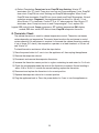
1. Control Board Layout
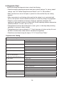
2. Display Module Layout
DISPLAY MODULE
RIBBON CABLE
E1
E2
CONTROL BOARD
Fig. 1
Compressor (115VAC)
Power Supply Input (115VAC)
Cabinet Thermistor
Door Switch (5VDC)
Evaporator Fan Motor
(12VDC)
Control Board
Display Module
Ribbon Cable
Display Module
Control Board
Compressor Icon
Display
Defrost Icon
Evaporator Fan Motor Icon
Power
Button
"P" Set
Button
"+" Up
Button
"-" Down
Button
Alarm Icon
°C
°F
°F LED
Cabinet Temperature LEDs
Fig. 2

18
3. Control Board Check
Before replacing a CB that does not show a visible defect and that you suspect is bad,
always conduct the following check procedure. This procedure will help you verify your
diagnosis. Always choose a neutral (W wire) to establish a good neutral connection
when checking AC voltage (115VAC).
Startup and Cool Down:
1) Press the power button for 2 sec. to turn off the appliance.
2) Unplug the appliance from the electrical outlet.
3) Remove the top panel. Check all wiring connections. Conrm that the power cord,
EvapFM, Comp, DS, and CTh are all properly connected to CB and ground connection
(GND) is properly connected to the frame.
4) Secure the top panel to prevent it from falling over when checking voltages and
CBitems.
5) Secure (tape) DS in the door closed position.
6) Plug the appliance back in. °F LED turns on. Diagnosis: Conrm that °F LED is on.
Ifnot, check CB POWER connector for 115VAC. If 115VAC is not present, check power
supply and power cord connection. If 115VAC is present and °FLED is not on, replace
CB.
7) Press the power button for 2 sec. to turn on the appliance.
8) Check that CT LEDs and EvapFM icon turn on. If not, check for 115VAC at the POWER
connector on CB. If 115VAC is not present, check power cord and power supply.
If115VAC is present, and DM is not on (°F and CT LEDs and EvapFM icon), replace
CB.
9) If °F and CT LEDs are on but EvapFM icon is not, conrm DS is engaged (pushed in,
contacts open). Check across DS for 5VDC. If 5VDC is not present, check DS activation
lever and DS continuity. Note: DS contacts are open when DS is engaged (door closed).
If 5VDC is present, check CB EvapFM connector for 12VDC. If 12VDC is not present,
replace CB. If 12VDC is present, check EvapFM wiring connector for loose connection,
EvapFM continuity, and fan blade for binding.
10) Defrost:
This appliance defrosts every 6 hrs. for 30 min. Defrost is an off-cycle defrost.
a) Manual Defrost Initiation: To initiate a manual defrost, press and hold the "+" button
until the defrost icon turns on. 30-min.DTstarts. EvapFM continues. If Comp run
time < 3 min., Comp icon and Comp continue until 3-min. Comp run timer terminates.
Once 3-min. Comp run timer terminates, Comp icon turns off, Comp de-energizes,
and 30-min. DT starts. Diagnosis: If defrost icon is on, conrm that Comp
de-energizes. If not, conrm Comp run time > 3min. If Comp continues after 3-min.
Comp run timer terminates, replace CB.

19
b) DefrostTermination: Comp icon is on. EvapFM icon ashing. 30-min. DT
terminates. 6-hr. DTstarts. Comp icon turns on and Comp energizes. 2-min. EvapFM
timer starts. EvapFM icon starts ashing and EvapFM de-energizes. When 2-min.
EvapFM timer terminates, EvapFM icon turns steady and EvapFM energizes. Normal
operation resumes. Diagnosis: Has appliance been in defrost for 30 min.? If not,
allow 30-min. DT to terminate. Conrm CTh is 4°F above setpoint. After 30-min. DT
terminates, does Comp icon turns on and Comp energize? If not, replace CB.
Legend: CB–control board; Comp–compressor; CT–cabinet temperature; DM–display
module; DS–door switch; DT–defrost timer; EvapFM–evaporator fan motor
G. Thermistor Check
The cabinet thermistor is used for cabinet temperature control. Thermistor resistance
varies depending on temperature. The control board monitors the resistance to control
system operation. No adjustment is required. In the event the cabinet thermistor reading
is out of range (Pr1 alarm), the compressor operates on a xed time basis of 10-min. on
and 10-min. off.
To check thermistor resistance, follow the steps below.
1) Press the power button for 2 sec. to turn the appliance off, then unplug the appliance.
2) Remove the evaporator shroud.
3) Disconnect and remove the evaporator thermistor.
4) Immerse the thermistor sensor portion in a glass containing ice and water for 2 to 3 min.
5) Check the resistance between the wires at the thermistor connector. Normal reading is
within 14.0 to 19.0 kΩ. If outside the normal reading, replace the thermistor.
6) Reconnect and replace the thermistor in its correct position.
7) Replace the evaporator shroud in its correct position.
8) Plug the appliance back in. Press the power button for 2 sec. to turn the appliance on.

20
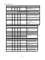
H. Diagnostic Chart
Before consulting the diagnostic charts, check the following:
• Check the cabinet temperature setpoint and factory default settings. For factory default
settings, see "II.B. Cabinet Temperature and Defrost" and "II.J. Service Menu."
• Make sure the doors are not left open or opened too often and that they are sealing
properly.
• Make sure product is not blocking airow and that the cabinet is not overloaded with
warm or hot product. Product should be allowed to cool before putting in the appliance.
• Check for correct installation and proper voltage per appliance nameplate. This
appliance is approved for indoor or outdoor use. Normal operating ambient temperature
should be within 61°F to 95°F (16°C to 35°C).
• The appliance should not be located next to ovens, grills, or other high heat producing
equipment or exposed to direct sunlight.
• The appliance must have a minimum of 1" (3 cm) clearance at bottom and top. Air must
be able to circulate freely under, behind, and above the appliance.
• Check the control board using the steps in "II.F.3. Control Board Check."
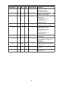
1. Appliance Not Cooling
Appliance Not Cooling - Possible Cause
1.
Power Supply
a)
Unplugged, off, blown fuse, or tripped or defective breaker.
b)
Loose connection.
c)
Not within specications.
2.
Cord and Plug
a)
Loose connection.
b)
Defective.
3.
Wiring
a)
Loose connection or open.
b)
Faulty.
4.
Power Button (control board)
a)
Turned "OFF."
b)
Defective.
5.
Control Board and Display Module
See "II.J. Alarm Safeties."
and "II.F.3. Control Board Check."
a)
In alarm.
b)
Defective.
6.
Door Switch
a)
Door open.
b)
Defective.
7.
Evaporator Fan Motor
a)
Fan blade binding.
b)
Defective.
8.
Compressor
a)
Compressor external protector open or defective.
b)
Motor winding open.
c)
PTC relay contacts bad or coil winding open.
d)
Inefficient.
9.
Condenser
a)
Dirty.
10.
Evaporator
a)
Dirty or frozen up.
11.
Refrigerant/Refrigerant Lines
a)
Gas leak, low charge.
b)
Refrigerant lines restricted.
La page est en cours de chargement...
La page est en cours de chargement...
La page est en cours de chargement...
La page est en cours de chargement...
La page est en cours de chargement...
La page est en cours de chargement...
La page est en cours de chargement...
La page est en cours de chargement...
La page est en cours de chargement...
La page est en cours de chargement...
La page est en cours de chargement...
La page est en cours de chargement...
La page est en cours de chargement...
La page est en cours de chargement...
La page est en cours de chargement...
La page est en cours de chargement...
La page est en cours de chargement...
La page est en cours de chargement...
La page est en cours de chargement...
-
 1
1
-
 2
2
-
 3
3
-
 4
4
-
 5
5
-
 6
6
-
 7
7
-
 8
8
-
 9
9
-
 10
10
-
 11
11
-
 12
12
-
 13
13
-
 14
14
-
 15
15
-
 16
16
-
 17
17
-
 18
18
-
 19
19
-
 20
20
-
 21
21
-
 22
22
-
 23
23
-
 24
24
-
 25
25
-
 26
26
-
 27
27
-
 28
28
-
 29
29
-
 30
30
-
 31
31
-
 32
32
-
 33
33
-
 34
34
-
 35
35
-
 36
36
-
 37
37
-
 38
38
-
 39
39


dans d''autres langues
- English: Hoshizaki HR24B User manual
Documents connexes
-
Hoshizaki PR46A-D2 Manuel utilisateur
-
Hoshizaki SR60A-24M Manuel utilisateur
-
Hoshizaki EF1A-FS Manuel utilisateur
-
-
-
Hoshizaki RM-7-HC Manuel utilisateur
-
-
Hoshizaki EUR48A Manuel utilisateur
-
-