
Models
Undercounter
Worktop
Prep Table
Steelheart Series
Refrigerated Kitchen Equipment
Service Manual
Number: 73217
Issued: 11-2-2018
Revision: 11-18-2019
hoshizakiamerica.com

2
WARNING
Only qualied service technicians should install and service the appliance. To
obtain the name and phone number of your local Hoshizaki Certied Service
Representative, visit www.hoshizaki.com. No service should be undertaken until
the technician has thoroughly read this Service Manual. Failure to service and
maintain the appliance in accordance with this manual will adversely affect safety,
performance, component life, and warranty coverage. Proper installation is the
responsibility of the installer. Product failure or property damage due to improper
installation is not covered under warranty.
Hoshizaki provides this manual primarily to assist qualied service technicians in the
service of the appliance.
Should the reader have any questions or concerns which have not been satisfactorily
addressed, please call, send an e-mail message, or write to the Hoshizaki Technical
Support Department for assistance.
Phone: 1-800-233-1940; (770) 487-2331
Fax: 1-800-843-1056; (770) 487-3360
E-mail: techsuppor[email protected]
618 Highway 74 South
Peachtree City, GA 30269
Attn: Hoshizaki Technical Support Department
Web Site: www.hoshizaki.com
NOTE: To expedite assistance, all correspondence/communication MUST include the
following information:
• Model Number
• Serial Number
• Complete and detailed explanation of the problem.

3
IMPORTANT
This manual should be read carefully before the appliance is serviced. Read
the warnings and guidelines contained in this booklet carefully as they provide
essential information for the continued safe use, service, and maintenance of the
appliance. Retain this booklet for any further reference that may be necessary.
CONTENTS
Important Safety Information ................................................................................................. 4
I. Construction and Refrigeration Circuit Diagram ................................................................. 8
A. Construction .................................................................................................................. 8
B. Refrigeration Circuit Diagram ...................................................................................... 10
II. Sequence of Operation and Service Diagnosis ................................................................11
A. Sequence of Operation Flow Chart ..............................................................................11
1. Undercounter and Work Top: Refrigerator ...............................................................11
2. Prep Table: Refrigerator ......................................................................................... 12
3. Undercounter and Work Top: Freezer .................................................................... 13
B. Service Diagnosis ....................................................................................................... 14
1. Refrigerator/Freezer/Prep Table ............................................................................. 15
C. Control Module Check ................................................................................................. 20
D. Thermistor Check ........................................................................................................ 22
E. Cabinet Temperature Control Dial (CTCD) .................................................................. 23
F. Diagnostic Table ........................................................................................................... 23
III. Controls and Adjustments ............................................................................................... 26
A. Temperature Settings .................................................................................................. 26
B. Defrost ......................................................................................................................... 26
C. Safety Devices ............................................................................................................ 28
D. Perimeter and Mullion Heaters .................................................................................... 28
IV. Refrigeration Circuit and Component Service Information.............................................. 29
A. Refrigeration Circuit Service Information .................................................................... 31
B. Component Service Information .................................................................................. 34
V. Preparing the Appliance for Periods of Non-Use ............................................................. 35
VI. Disposal .......................................................................................................................... 36
VII. Technical Information ..................................................................................................... 37
A. Electrical and Refrigerant Data ................................................................................... 37
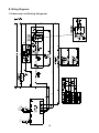
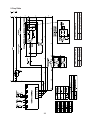
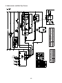
B. Wiring Diagrams .......................................................................................................... 38
1. Undercounter and Worktop: Refrigerator ................................................................ 38
2. Prep Table .............................................................................................................. 39
3. Undercounter and Work Top: Freezer .................................................................... 40

4
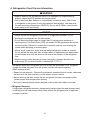
DANGER
Risk of Fire or Explosion
Flammable Refrigerant Used
• Follow handling instructions carefully
in compliance with U.S. government
regulations.
• Do not use mechanical devices to defrost.
• Do not puncture refrigerant tubing. Risk
of re or explosion due to puncture
of refrigerant tubing; follow handling
instructions carefully.
• Component parts shall be replaced with
like components.
• Servicing shall be done by factory
authorized service personnel to minimize
the risk of possible ignition due to incorrect
parts or improper service.
• Consult instruction manual/service manual
before attempting to install or service this
product. All safety precautions must be
followed.
• Dispose of properly in accordance with
federal or local regulations.
• Do not place any potential ignition sources
in or near the appliance.
Important Safety Information
Throughout this manual, notices appear to bring your attention to situations which could
result in death, serious injury, damage to the appliance, or damage to property.
DANGER
Indicates a hazardous situation that, if not avoided, will result in
death or serious injury.
WARNING
Indicates a hazardous situation that, if not avoided, could result
in death or serious injury.
NOTICE
Indicates a situation that, if not avoided, could result in damage
to the appliance or property.
IMPORTANT
Indicates important information about the use and care of the
appliance.
Risque De Feu Ou D'Explosion
Le Frigorigène Est Inammable
• Suivre attentivement les instructions
de manipulation conformément à la
réglementation gouvernementale.
• Ne pas utiliser d'appareils mécaniques
pour dégivrer le réfrigérateur.
• Ne pas perforer la tubulure contenant le
frigorigène. Risque de feu ou d'explosion
si la tubulure contenant le frigorigène
est perforée; suivre les instructions de
manutention avec soin.
• Les pièces des composants doivent être
remplacées par des pièces et accessoires
équivalents.
• L’entretien doit être effectué par le
personnel de service autorisé par le
fabricant an de minimiser les risques
d’inammation attribuables à l’installation
d’une pièce inadéquate ou à la mauvaise
exécution du service.
• Consulter le manuel du propriétaire/
guide de réparation avant de tenter une
réparation. Toutes les mesures de sécurité
doivent être respectées.
• Éliminer conformément aux règlements
fédéraux ou locaux.
• Ne placez aucune source d’inammation
potentielle dans ou près de l’appareil.

5
WARNING
The appliance should be destined only to
the use for which it has been expressly
conceived. Any other use should be
considered improper and therefore
dangerous. The manufacturer cannot be
held responsible for injury or damage
resulting from improper, incorrect, and
unreasonable use. Failure to install,
operate, and maintain the appliance
in accordance with this manual will
adversely affect safety, performance,
component life, and warranty coverage.
To reduce the risk of death, electric
shock, serious injury, or re, follow
basic precautions including the
following:
• Only qualied service technicians should
install and service the appliance.
• Wear appropriate personal protective
equipment (PPE) when servicing the
appliance.
• The appliance must be installed in
accordance with applicable national, state,
and local codes and regulations.
• Appliance is heavy. Use care when lifting
or positioning. Work in pairs when needed
to prevent injury or damage. Do not lift
using the top section or the doors/drawers.
• To reduce the risk of electric shock, do not
touch the plug with damp hands.
• Unplug the appliance before servicing.
• The appliance requires an independent
power supply of proper capacity. See the
nameplate for electrical specications.
Failure to use an independent power
supply of proper capacity can result in a
tripped breaker, blown fuse, damage to
existing wiring, or component failure. This
could lead to heat generation or re.
• THE APPLIANCE MUST BE
GROUNDED. The appliance is equipped
with a NEMA5-15 three-prong grounding
plug to reduce the risk of potential
shock hazards. It must be plugged into a
properly grounded, independent 3-prong
wall outlet. If the outlet is a 2-prong outlet,
it is your personal responsibility to have
a qualied electrician replace it with a
properly grounded, independent 3-prong
wall outlet. Do not remove the ground
prong from the power cord and do not use
an adapter plug. Failure to follow these
instructions may result in death, electric
shock, or re.
• Do not use an extension cord.
• Do not use an appliance with a damaged
power cord. The power cord should not be
altered, jerked, bundled, weighed down,
pinched, or tangled. Such actions could
result in electric shock or re. To unplug
the appliance, be sure to pull the plug, not
the cord, and do not jerk the cord.
• The GREEN ground wire in the factory-
installed power cord is connected to the
appliance. If it becomes necessary to
remove or replace the power cord, be
sure to connect the power cord's ground
wire.
• Do not splash, pour, or spray water
directly onto or into the appliance. This
might cause short circuit, electric shock,
corrosion, or failure.
• Do not make any alterations to the
appliance. Alterations could result in
electric shock, injury, re, or damage to
the appliance.
• The appliance is not intended for use by
persons (including children) with reduced
physical, sensory, or mental capabilities,
or lack of experience and knowledge,
unless they have been given supervision
or instruction concerning use of the
appliance by a person responsible for
their safety.

6
• Do not block air inlets or outlets, otherwise
cooling performance may be reduced.
• Do not tightly pack the cabinet. Allow some
space between items to ensure good air
ow. Also allow space between items and
interior surfaces.
• Do not put warm or hot foods in the cabinet.
Let them cool rst, or they will raise the
cabinet temperature and could deteriorate
other foods in the cabinet or overload the
appliance.
• Food storage and handling must comply with
applicable codes and regulations.
• All foods should be wrapped in plastic lm
or stored in sealed containers. Otherwise
foods may dry up, pass their smells onto
other foods, cause frost to develop, result in
poor appliance performance, or increase the
likelihood of cross-contamination. Certain
dressings and food ingredients, if not
stored in sealed containers, may accelerate
corrosion of the evaporator, resulting in
failure.
• Do not store items near air outlets.
Otherwise, items may freeze up and
crack or break causing a risk of injury or
contamination of other food.
WARNING, continued
• Children should be properly supervised
around the appliance.
• Do not climb, stand, or hang on the
appliance or doors/drawers or allow
children or animals to do so. Do not climb
into the appliance or allow children or
animals to do so. Death or serious injury
could occur or the appliance could be
damaged.
• Be careful not to pinch ngers when
opening and closing the doors/drawers
or rail cover (prep table models) or when
handling food pans. Be careful when
opening and closing the doors/drawers or
rail cover when children are in the area.
• Open and close the doors/drawers and
rail cover (prep table models) with care.
Opening the doors/drawers or rail cover
too quickly or forcefully may cause
injury or damage to the appliance or
surrounding equipment.
• Do not use combustible spray or place
volatile or ammable substances in or
near the appliance. They might catch re.
• Keep the area around the appliance clean.
Dirt, dust, or insects in the appliance
could cause harm to individuals or
damage to the equipment.
• Do not throw anything onto the shelves
or load any single shelf with more than
120lb. (54.5 kg) of product. They might fall
off and cause injury.
• Do not load any single drawer with more
than 75 lb. (34 kg) of product. Depending
on the weight of product in the drawers,
secure the unit as necessary to prevent it
from overturning. Do not open more than
one drawer at a time.
• The appliance is designed only for
temporary storage of food. Employ
sanitary methods. Use for any other
purposes (for example, storage of
chemicals or medical supplies such
as vaccine and serum) could cause
deterioration of stored items.

7
WARNING, continued
Additional Warnings for Prep Table
Models
• The entire rail must always be covered
by rail dividers and pans (1/6 size, up
to 6"(15cm)deep). Otherwise, the
appliance will not cool properly.
• Use only 1/6 size pans up to 6"(15cm)
deep. Do not use damaged pans.
• Ingredients must be pre-chilled to 37°F
(3°C) or less before placing in rail.
• Keep the rail cover closed when not
actively preparing food.
• The rail is for keeping ingredients cool
while preparing food. If not actively
preparing food for a long period such
as overnight, seal pans with plastic
wrap in addition to closing the rail cover.
Depending on conditions, the cabinet
temperature setting may need to be
adjusted to prevent items from freezing.
Alternatively, seal ingredients and store
them in a refrigerator or freezer.
NOTICE
• Protect the oor when moving the
appliance to prevent damage to the oor.
• Keep ventilation openings, in the
appliance enclosure or in the built-in
structure, clear of obstruction. Do not
place anything on top of the appliance in
an undercounter installation. There must
be at least 1.5" (4 cm) overhead clearance
for proper ventilation. The factory-installed
rear bumpers must be in place to ensure
proper rear clearance. Blockage of airow
could negatively affect performance and
damage the appliance.
• Do not allow the appliance to bear any
outside weight.
• To prevent deformation or cracks, do not
spray insecticide onto the plastic parts or
let them come into contact with oil.
• To avoid damage to the gasket, use only
the door/drawer handle when opening
and closing.
• To avoid damage to the top seal, do not lift
the appliance by the top panel or remove
the top panel.
Additional Notice for Prep Table
Models
• Do not place anything on top of the rail
hood or rail cover and do not lift the
appliance by the rail hood or rail cover.
The rail hood and rail cover are not
designed to bear any outside weight.

8
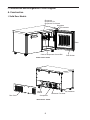
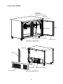
I. Construction and Refrigeration Circuit Diagram
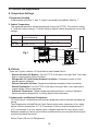
A. Construction
1. Solid Door Models
Compressor
Condenser Fan Motor
Condenser
Rear Panel
Thermometer
Door
Door Gasket
Nameplate
• Evaporator
• Evaporator Fan
• Evaporator Fan Shroud
Cabinet Temperature Control Dial
Model Shown: UF60A
Model Shown: UF60A
Control
Module

9
2. Glass Door Models
Compressor
Condenser Fan Motor
Condenser
Rear Panel
Thermometer
Door
Door Gasket
Nameplate
• Evaporator
• Evaporator Fan
• Evaporator Fan Shroud
Cabinet Temperature Control Dial
Model Shown: UR48A-GLP01
Channel
Control
Module
Model Shown: UR48A-GLP01
LED Driver
LED Lights

10
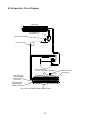
B. Refrigeration Circuit Diagram
Evaporator Fans
(1, 2, or 3 depending on model)
Evaporator
Compressor
Drier
Condenser Fan
Condenser
Prep Table and Freezer Models: Defrost Heater
Capillary Tube
High-Pressure Switch
Cabinet Thermistor
Prep Table and
Freezer Models:
Defrost Safety
Thermostat
Prep Table and
Freezer Models:
Defrost Thermistor

11
II. Sequence of Operation and Service Diagnosis
The steps in the sequence are as outlined below.
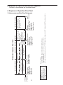
A. Sequence of Operation Flow Chart
1. Undercounter and Work Top: Refrigerator
Legend:
Comp-compressor
ConFM-condenser fan motor
CTh-cabinet thermistor
EvapFM-evaporator fan motor
Note: Delays
a) 2-min. minimum Comp on timer starts when Comp energizes.
b) 2-min. minimum Comp off timer starts when Comp de-energizes.
c) 20-min. defrost time.
d) If evaporator temperature raises above 41°F (10°C) during the cooling cycle, 4-hr. DT is skipped. 8-hr. DT becomes mandatory.
*
1. Startup/Cool Down
Comp energized
ConFM energized
EvapFM energized
4-hr. DT starts
8-hr. DT starts
Comp de-energized
ConFM de-energized
EvapFM de-energized
Refrigerator Sequence Flow Chart
2. Cool Down Achieved
4. Defrost
CTh above setpoint
CTh cools to setpoint
CTh above
setpoint
Defrost Termination:
43°F (6.1°C) achieved
or 20 min. defrost timer
terminated.
CTh in control
4-hr. or 8-hr DT terminates
20-min. DT starts
Comp de-energized
ConFM de-energized
EvapFM energized
Defrost:
Time/Temp achieved.
Power on
Red LED On
(5-sec. Delay)
2-min. Comp off
timer starts
Green LED Flashes. If Red LED Flashes, check CTh
2-min. Comp on
timer starts
Evap. Temp.
reaches 43°F (6.1°C) or
20-min. DT terminates
Comp energized
ConFM energized
EvapFM energized
*
*
*
CTh in control
5. Defrost Termination
4-hr. or 8-hr. DT
terminates
Evap. temp. at or
below 41°F (5°C)
Defrost
Terminated
3. Cool Down Restarts

12
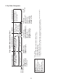
2. Prep Table: Refrigerator
Prep Table Top Sequence Flow Chart
2. Cool Down Achieved
3. Cool Down Restarts
EvapFM energized
Comp de-energized
ConFM de-energized
4. Defrost
CTh above setpoint
CTh cools to setpoint
CTh above
setpoint
Defrost Termination:
46°F (7.7°C) achieved or
45 min. backup defrost
timer terminated.
CTh in control
1. Startup/Cool Down
Comp energized
ConFM energized
EvapFM energized
6-hr. DT starts
6-hr. DT terminates
5-min. minimum DT starts
45-min. maximum DT starts
DH energized
Comp de-energized
ConFM de-energized
EvapFM de-energized
Defrost:
Time/Temp achieved.
Power on
Red LED On
(5-sec. Delay)
Legend:
Comp-compressor
ConFM-condenser fan motor
CTh-cabinet thermistor
DH-defrost heater
DT-defrost timer
DTh-defrost thermistor
EvapFM-evaporator fan motor
Note: Delays
a) 2-min. minimum Comp on timer starts when Comp energizes.
b) 2-min. minimum Comp off timer starts when Comp de-energizes.
c) 5-min. minimum defrost time.
d) 45-min. maximum defrost time.
e) DOT (drip off time) 1-min. Comp/ConFM delay timer starts when defrost termination temperature is met (drip off time (DOT)).
f) If evaporator temperature raises above 50°F (10°C) during the cooling cycle, 6-hr. DT resets.
*
2-min. Comp off
timer starts
2-min. Comp on
timer starts
Evap. Temp.
reaches 46°F (7.7°C)
DH de-energized
6-hr DT starts
After DOT Delay:
Comp energized
ConFM energized
EvapFM energized
*
*
*
*
*
*
DTh in control
5. Defrost Termination
6-hr. DT terminates
Evap. temp. at or
below 50°F (10°C)
Defrost
Terminated
Green LED Flashes. If Red LED Flashes, check CTh or DTh

13
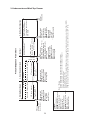
3. Undercounter and Work Top: Freezer
Freezer Sequence Flow Chart
Legend:
Comp-compressor
ConFM-condenser fan motor
CTh-cabinet thermistor
DH-defrost heater
DT-defrost timer
DTh-defrost thermistor
EvapFM-evaporator fan motor
MH-mullion heater
PH-perimeter heater
1. Startup/Cool Down
2. Cool Down Achieved
Comp energized
ConFM energized
EvapFM energized
MH energized
PH energized
8-hr. DT starts
CTh in control
4. Defrost
Comp de-energized
ConFM de-energized
EvapFM de-energized
MH de-energized
PH de-energized
5. Defrost Termination
DTh in control
2-min. Comp off
timer starts
2-min. Comp on
timer starts
Defrost Termination:
50°F (°10C) achieved or
1 hr. backup defrost timer
terminated.
8-hr. DT terminates
Evap. temp. below 41°F (5°C)
5-min. minimum DT starts
60-min. maximum DT starts
DH energized
Comp de-energized
ConFM de-energized
EvapFM de-energized
MH de-energized
PH de-energized
Note: Delays
a) 2-min. minimum Comp on timer starts when Comp energizes.
b) 2-min. minimum Comp off timer starts when Comp de-energizes.
c) 5-min. minimum defrost time.
d) 1-hr. maximum defrost time.
e) DOT (drip off time) 3-min. Comp/ConFM delay timer starts when defrost termination temperature is met (drip off time (DOT)).
f) FDD (fan delay after defrost) EvapFM starts once 7-min. EvapFM delay timer terminates or DTh reaches 25°F (-4°C).
*
DH de-energized
8-hr. DT starts
After DOT Delay:
Comp energized
ConFM energized
MH energized
PH energized
After FDD
EvapFM energized
*
*
Defrost
Terminated
8-hr. DT terminates
Evap. temp. below 41°F (5°C)
Power on
Red LED On
(5 sec. Delay)
4-hr continuous compressor
run timer terminates
Green LED Flashes. If Red LED Flashes, check CTh or DTh
3. Cool Down Restarts
CTh above setpoint CTh cools to setpoint
CTh above
setpoint
*
*

14
B. Service Diagnosis
DANGER
Risk of Fire or Explosion
Flammable Refrigerant Used
• Follow handling instructions carefully
in compliance with U.S. government
regulations.
• Do not use mechanical devices to defrost.
• Do not puncture refrigerant tubing. Risk
of re or explosion due to puncture
of refrigerant tubing; follow handling
instructions carefully.
• Component parts shall be replaced with
like components.
• Servicing shall be done by factory
authorized service personnel to minimize
the risk of possible ignition due to
incorrect parts or improper service.
• Consult instruction manual/service manual
before attempting to install or service this
product. All safety precautions must be
followed.
• Dispose of properly in accordance with
federal or local regulations.
• Do not place any potential ignition sources
in or near the appliance.
Risque De Feu Ou D'Explosion
Le Frigorigène Est Inammable
• Suivre attentivement les instructions
de manipulation conformément à la
réglementation gouvernementale.
• Ne pas utiliser d'appareils mécaniques
pour dégivrer le réfrigérateur.
• Ne pas perforer la tubulure contenant le
frigorigène. Risque de feu ou d'explosion
si la tubulure contenant le frigorigène
est perforée; suivre les instructions de
manutention avec soin.
• Les pièces des composants doivent être
remplacées par des pièces et accessoires
équivalents.
• L’entretien doit être effectué par le
personnel de service autorisé par le
fabricant an de minimiser les risques
d’inammation attribuables à l’installation
d’une pièce inadéquate ou à la mauvaise
exécution du service.
• Consulter le manuel du propriétaire/
guide de réparation avant de tenter une
réparation. Toutes les mesures de sécurité
doivent être respectées.
• Éliminer conformément aux règlements
fédéraux ou locaux.
• Ne placez aucune source d’inammation
potentielle dans ou près de l’appareil.
WARNING
• The appliance should be diagnosed and repaired only by qualied service
personnel to reduce the risk of death, electric shock, serious injury, or re.
• Wear appropriate personal protective equipment (PPE) when servicing the
appliance.
• Risk of electric shock. Use extreme caution and exercise safe electrical practices.
• Moving parts (e.g., fan blade) can crush and cut. Keep hands clear.
• Appliance is heavy. Use care when lifting or positioning. Work in pairs when
needed to prevent injury or damage.
• Make sure all food zones are clean after the appliance is serviced.

15
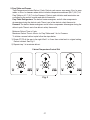
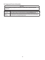
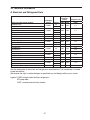
1. Refrigerator/Freezer/Prep Table
The diagnostic procedure is a sequence check that allows you to diagnose the electrical
system and components. Before proceeding, check for correct installation and proper
voltage per nameplate.
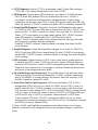
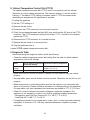
See the table for default cabinet temperature control dial settings.
Model Default Cabinet Temperature
Control Dial Setting
Approximate Default Temperature
Undercounter
Worktop
Between 4 and 5 Refrigerator: 34°F (1°C)
Freezer: -5°F (-21°C)
Prep Table Between 4 and 5 34°F (1°C)
The diagnostic procedure is a sequence check that allows you to diagnose the electrical
system and components. Before proceeding, check for correct installation and proper
voltage per nameplate.
Conrm that the appliance location meets factory requirements:
• This appliance is not intended for outdoor use. Normal operating ambient
temperature should be within 45°F to 86°F (7°C to 30°C).
• The appliance should not be located next to ovens, grills, or other high heat
producing equipment. Check CM using the steps in "II.C. Control Module Check."
Note: • When checking voltage (115VAC), always choose a neutral white (W) wire to
establish a good neutral connection.
• Control module has high and low voltage protection. If off on either protection,
no LED is visible and all components are off.
High Voltage: 135VAC
Low Voltage: 90VAC
• Solid red LED for 5 sec. at startup.
• Flashing green LED: Normal operation.
• Flashing red LED: check cabinet thermistor and defrost thermistor (if applicable).
• Control module has a 2 min. minimum on time and 2 min. minimum off time
for Comp.
1) Unplug the appliance from the electrical outlet.
2) Remove the rear panel.
3) Plug the appliance back into the electrical outlet. If appliance was in defrost when power
supply was disconnected, defrost is terminated and normal cooling cycle begins when
power supply is reconnected.
4) Startup/Cool Down–There is a slight delay (solid red LED for 5 sec., then ashing
green LED). Temperature above setpoint at CTh and if applicable, conrm appliance is
not in a defrost cycle (PT and Freezers). Comp, CondFM, and EvapFM energize. 2-min.
Comp on timer starts.
Freezers: PH and MH energize.
a) CTh Diagnosis: If CTh fails, a red LED ashes along with the green LED on the CM.
Conrm CTh is properly connected to CM. Check Ohm reading of CTh.
See "II.D. Thermistor Check." Replace as needed.

16
b) CTCD Diagnosis: Conrm CTCD is set between 4 and 5. Check Ohm reading of
CTCD. See "II.E) Cabinet Temperature Control Dial (CTCD)."
c) CM Diagnosis: Conrm green LED is ashing. If not, check for 115VAC between
CM 2 (L) black (BK) wire and CM 3 (N) neutral white (W) wire. If 115VAC is
not present, check power cord connections and breaker/fuse. Conrm wiring
connections are secure for both CM 2 (L) black (BK) (power supply) and CM 3 (N)
white (W) (neutral). If 115VAC is present and green LED is not ashing, replace CM.
d) Comp/CondFM Diagnosis: Check that Comp and ConFM energize. Next, check
for 115VAC at CM 1 (C) brown(BR) wire to neutral white (W) wire. If 115VAC is not
present at CM 1 (C) (BR) to neutral (W), check CTh status. See "II.D. Thermistor
Check." If CTh ohm reading is in proper range, replace CM. If 115VAC is present,
check HPS continuity (if applicable). See "f) HPS Activation" below.
Comp: If 115VAC is present, check Comp external overload, start cap, start relay,
and Comp motor windings. Replace as needed.
CondFM: If 115VAC is present, check fan blade for binding, then check ConFM
motor windings.
e) EvapFM Diagnosis: Check that EvapFM(s) energize. If not, check for 115VAC at
CM 5 (F) dark blue (DBU) wire to neutral white (W) wire. If 115VAC is not present,
replace CM. If 115VAC is present, check fan blades for binding, then check EvapFM
motor windings.
f) HPS Activation: Check continuity of HPS. If open, allow time for system pressure
to equalize and HPS to reset. If HPS does not reset, replace HPS and diagnose
reason for HPS activation. Conrm ConFM is energized and fan blade turns freely.
Check that the condenser coil is not clogged or restricted. Check that there are no
restrictions in the refrigeration circuit (drier).
g) PH and MH Diagnosis (Freezer only): PH and MH follow Comp operation. When
Comp is energized, PH and MH are energized. If 115VAC is present, check amp
draw of PH and MH. If an amp reading is not present, check the continuity of PH
and MH. If defective, replace PH or MH.
h) Glass Door Cabinet Light Diagnosis: LED(s) are activated by CLS. If CLS is
engaged and LED(s) fail to turn on, check for 115VAC at both CLS (Y) wires to a
neutral white (W) wire. If 115VAC is present on one end and not the other, check
CLS continuity. If open replace CLS. If CLS is closed and 115VAC is present on both
CLS (Y) wires to a neutral (W), check for check for 24VDC at DCD black (BK) wire
to DCD red (R) wire. If 24VDC is not present, check continuity of DCD driver.
If open, replace DCD driver. If 24VDC is present and LED(s) are not on, check
wiring harness and wiring connections from DCD to LED(s). Ifconnections are good
and LED(s) are not on, replace LED(s).
If Comp, ConFM, and EvapFM are energized and the cabinet does not cool down,
check for a restriction in the refrigeration circuit, low refrigerant charge, or inefficient
Comp.

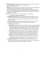
17
5) Cool Down Achieved–Temperature cools to setpoint. Comp and ConFM de-energize.
UC/WT Refrigerators and Freezers: EvapFM de-energizes.
Prep Table: EvapFM continues.
Diagnosis: If temperature setpoint achieved and Comp, ConFM, and EvapFM(except
PT models) does not de-energize, check CTh and CTCD continuity.
See "II.D. Thermistor Check." and "II.E) Cabinet Temperature Control Dial (CTCD)."
If CTh or CTCD is defective, replace. If CTh and CTCD are good and either the Comp,
ConFM, and/or EvapFM (except PT models) continue, or if EvapFM on PT models
de-energizes, replace CM.
6) Defrost–Manually initiated defrost, off cycle defrost, and time-initiated
temperature-terminated heated defrost.
1a) Manually-Initiated (All): Turn the CTCD all the way to the right. Wait 1 to 3 sec.
then back to original setting. Defrost initiated. If defrost does not initiate, wait 1 to
2 min. and repeat process. Note: When refrigerator defrost is manually-initiated
EvapFM continues.
1b) Off Cycle-Inititiated: Off cycle between cooling cycles. CTh cools below CTCD.
Setting satised. Comp and CondFM de-energize. EvapFM energizes.
1c) Time/Temperature-Initiated:
(1) Refrigerator: 4-hr. defrost interval timer terminates. Control module checks CTh.
If CTh is at or below 41°F (5°C), defrost starts. If in defrost, Comp and CondFM
de-energize. EvapFM continues. 20-min. DT starts. If CTh is above 41°F (5°C),
defrost is delayed for 4 hrs. (8-hr. defrost interval timer). Once the 8-hr. defrost
interval timer terminates, defrost starts regardless of evaporator temperature.
(2) Prep Table: 6-hr. defrost timer terminates. Control module checks DTh. If DTh
is at or below 50°F (10°C), defrost starts. If in defrost, Comp, CondFM, and
EvapFM de-energize. DH energizes. 5-min. minimum DT starts and 45-min.
maximum DT starts. If DTh is above 50°F (10°C), defrost will not initiate.
(3) Freezer: 8-hr. defrost timer terminates. Control module checks DTh. If DTh is
at or below 41°F (5°C), defrost starts. If in defrost, Comp, ConFM, PH, MH,
and EvapFM de-energize. DH energizes. 5-min. minimum DT starts and 1-hr
maximum DT starts. If DTh is above 41°F (5°C), defrost will not initiate.
2a) Manually-Terminated: Turn the CTCD all the way to the right. Wait 1 to 3 sec.
then back to original setting. Defrost terminated. If DH continues or Comp does not
energize, make several more attempts of manual termination.

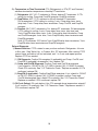
18
2b) Temperature or Time-Terminated: CTh (Refrigerator) or DTh (PT and Freezers)
achieves termination temperature or backup DT terminates.
(1) Refrigerator: 43°F (6.1°C) achieved or 20-min. backup DT terminates. If CTh
calling for cooling, Comp and CondFM energize. EvapFM continues.
(2) Prep Tables: 46°F (7.7°C) achieved or 45-min. backup DT terminates.
DH de-energizes. IfCTh calling for cooling, 1-min. Comp delay timer starts
(drip time). 1-min. Comp delay timer terminates. Comp, ConFM, and EvapFM
energize.
(3) Freezers: 50°F (10°C) achieved or 1-hr. backup DT terminates. DH de-energizes.
If CTh calling for cooling, 3-min. Comp delay timer starts (drip time) and
7-min. EvapFM delay timer starts. 3-min. Comp delay timer terminates. Comp
and ConFM energize. 4min. later, 7-min. EvapFM delay timer terminates and
EvapFM energizes.
Note: If DTh achieves 25°F before 7-min. EvapFM delay timer terminates, 7-min.
EvapFM delay timer terminates and EvapFM energizes.
Defrost Diagnosis:
1) Manual-Initiation: CTCD rotated to max. position and back. Refrigerator: 4-hr min.
or 8-hr max., Prep Table: 6-hr., or Freezer: 8-hr. DT terminates. After rotating CTCD
several times and defrost still not activated, wait 1 to 2 min. and repeat process.
Replace CTCD as needed.
(1) CM Diagnosis: Conrm DH energizes (if applicable) and Comp, ConFM, and
EvapFM (if applicable) de-energize. If not, replace CM.
(2) Comp and ConFM Diagnosis: Conrm Comp and ConFM de-energize.
If not, check for 115VAC at CM 1 (C) (BR) to neutral (W). If 115VAC is present,
Check DTh continuity. See "II.D. Thermistor Check." Replace as needed. If DTh
conrmed, replace CM.
(3) EvapFM (if applicable): Conrm EvapFM de-energizes. If not, check for 115VAC
at CM 5 (F) (DBU) to neutral (W). If 115VAC is present, conrm Comp and
ConFM de-energized. Next, check DTh continuity. See "II.D. Thermistor Check."
Replace as needed. If DTh conrmed, replace CM.
2) Off-Cycle Defrost: Off cycle defrost. Has CTh warmed above temperature setpoint?
If not, conrm CTh continuity. See "II.D. Thermistor Check." Replace as needed. If
CTh conrmed, replace CM.

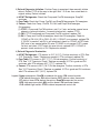
19
3) Defrost Diagnosis: Initiation: Conrm Comp is energized, then manually initiate
defrost. Rotate CTCD all the way to the right. Wait 1 to 5sec. then rotate back to
original setting. Defrost initiated.
a) UC/WT Refrigerator: Check that Comp and ConFM de-energize. EvapFM
continues.
b) Prep Table: Check that Comp, ConFM, and EvapFM de-energize. DH energizes.
c) Freezer: Check that Comp, ConFM, PH, MH, and EvapFM de-energize.
DHenergizes.
(1) CTCD: If Comp and ConFM continue, wait 1 to 2 min. and make several more
attempts of manual initiation. Ifmanual initiation fails, replace CTCD.
(2) CM: If CTCD conrmed and Comp and ConFM continue, replace CM.
(3) DH: If Comp and ConFM de-energize, check that DH energizes. Check for
115VAC at CM 4 (H) (R) to CM 3 (N) (W). If 115VAC is not present, replace CM.
If115VAC is present, and DH is not energized, check for 115VAC at DST black
(BK) wire to any neutral white (W) wire. If 115VAC is not present, DST is open.
Letcool and reset. If DST does not reset (close), replace DST. If 115VAC is
present, check continuity of DH. Replace as needed.
4) Defrost Diagnosis: Termination;
a) UC/WT Refrigerator: CTh warms to 43°F (6.1°C). Conrm continuity of CTh. See
"II.D. Thermistor Check." Replace as needed. If CTh conrmed, replace CM.
b) Prep Table: DTh warms to 46°F (7.7°C). DH de-energizes. Conrm continuity of
DTh. See "II.D. Thermistor Check." Replace as needed. If DTh is good and DH
continues after DTh achieves 46°F (7.7°C), replace CM.
c) Freezer: DTh warms to 50°F. (10°C) DH de-energizes. Conrm continuity of DTh.
See "II.D. Thermistor Check." Replace as needed. If DTh is good and DH continues
after DTh achieves 50°F (10°C), replace CM.
Legend: Comp–compressor; ConFM–condenser fan motor; CM–control module;
CTh–cabinet thermistor; DH–defrostheater; DST–defrost safety thermostat;
DT–defrost timer; DTh–defrost thermistor; EvapFM–evaporator fan motor;
HPS–high-pressure switch; MH–mullion heater; PH–perimeterheater;
CLS–cabinet light switch; CTCD–cabinet temperature control dial

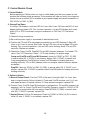
20
C. Control Module Check
1. Control Module
Before replacing a CM that does not show a visible defect and that you suspect is bad,
conduct the following check procedure. This procedure will help you verify your diagnosis.
Always choose a neutral (W) to establish a good power supply and neutral connection to
CM: 115VAC at CM 2 (L) (BK)
2. Startup/Cool Down
At startup, CM displays a solid red LED for 5 sec. After 5 sec. CM turns red LED off and
begins ashing a green LED. This is normal operation. If a red LED ashes (fault code),
check CTh or DTh for continuity and good connection to CM. See "II.D. Thermistor
Check."
1) Check all wiring connections.
2) Be sure the power supply is connected to the electrical outlet.
3) Conrm the CTh and DTh are properly connected (no red LED ashing). A Red LED
turns on for 5 sec. at startup. After 5 sec. the red LED turns off and a green LED starts
ashing. This is normal operation. If the red LED starts ashing, check CTh and DTh
continuity. Replace as needed.
4) Check that Comp, ConFM, EvapFM, PH and MH (freezers) energize. If not check CTh
status. See "II.D. Thermistor Check." If CTh ohm reading is in proper range,
Comp and ConFM and PH and MH (freezers); check for 115VAC at CM 1 (C) (BR)
to neutral white (W). If 115VAC is not present, replace CM. If 115VAC is present and
Comp energized and ConFM did not, check ConFM blades for binding and motor
winding continuity. If PH or MH (freezers) does not energize, check continuity, replace
as needed.
EvapFM; Check for 115VAC at CM 5 (F) (DBU) to neutral white (W). If 115VAC is not
present, replace CM. If115VAC is present, check EvapFM blades for binding and motor
winding continuity.
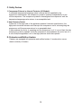
3. Defrost initiation
5) Manual Defrost Check: Turn the CTCD all the way to the right. Wait 1 to 3 sec. then
back to original setting. Defrost initiated. If Comp and ConFM continue, wait 1 to 2 min.
and repeat process of manual initiation. If Comp remains energized, replace CM.
6) Conrm Comp, ConFM, EvapFM (continues on refrigerators), PH and MH (freezers) de-
energize. If not, for Comp, ConFM and PH and MH (freezers), check for 115VAC at CM
1 (C) (BR) to neutral white (W) wire and for EvapFM CM 5 (F) (DBU) to neutral white
wire (W). If 115VAC is present, replace CM.
7) Heated Defrost: Conrm DH energizes. Check for 115VAC at CM 4 (H) (R) to neutral
white (W) wire. If 115VAC is not present, replace CM.
La page est en cours de chargement...
La page est en cours de chargement...
La page est en cours de chargement...
La page est en cours de chargement...
La page est en cours de chargement...
La page est en cours de chargement...
La page est en cours de chargement...
La page est en cours de chargement...
La page est en cours de chargement...
La page est en cours de chargement...
La page est en cours de chargement...
La page est en cours de chargement...
La page est en cours de chargement...
La page est en cours de chargement...
La page est en cours de chargement...
La page est en cours de chargement...
La page est en cours de chargement...
La page est en cours de chargement...
La page est en cours de chargement...
La page est en cours de chargement...
-
 1
1
-
 2
2
-
 3
3
-
 4
4
-
 5
5
-
 6
6
-
 7
7
-
 8
8
-
 9
9
-
 10
10
-
 11
11
-
 12
12
-
 13
13
-
 14
14
-
 15
15
-
 16
16
-
 17
17
-
 18
18
-
 19
19
-
 20
20
-
 21
21
-
 22
22
-
 23
23
-
 24
24
-
 25
25
-
 26
26
-
 27
27
-
 28
28
-
 29
29
-
 30
30
-
 31
31
-
 32
32
-
 33
33
-
 34
34
-
 35
35
-
 36
36
-
 37
37
-
 38
38
-
 39
39
-
 40
40


dans d''autres langues
- English: Hoshizaki SR60A-24M User manual
Documents connexes
-
Hoshizaki HR24C Manuel utilisateur
-
Hoshizaki EUR48A Manuel utilisateur
-
-
Hoshizaki PR46A-D2 Manuel utilisateur
-
-
-
-
Hoshizaki RM-7-HC Manuel utilisateur
-
-
Autres documents
-
Whirlpool SPIW318A2WF Air Conditioning Mode d'emploi
-
Avantco 360DFC13HCL Manuel utilisateur
-
Avantco 360ICFF7HC Manuel utilisateur
-
 Thermo Fisher Scientific Undercounter ADA Laboratory Refrigerator Manuel utilisateur
-
koban KCT20 Le manuel du propriétaire
-
 Pressalit RK1113 Mode d'emploi
-
Randell 9000-290/9000F-290 Manuel utilisateur
-
Intermatic DDT40 Mode d'emploi
-
Thermo Scientific Revco Slimline Mode d'emploi
-

