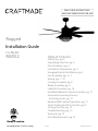
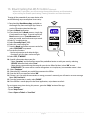
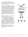
Craftmade RGD52 Guide d'installation
- Catégorie
- Ventilateurs ménagers
- Taper
- Guide d'installation

PRINTED IN CHINA
Table of Contents:
Safety Tips. pg. 3
Unpacking Your Fan. pg. 4
Parts Inventory. pg. 4
Installation Preparation. pg. 5
Hanging Bracket Installation. pg. 5
Fan Assembly. pgs. 6 - 7
Wiring. pgs. 7 - 8
Canopy Assembly. pg. 8
Blade Assembly. pg. 9
Light Kit Assembly. pg. 10
Handheld Remote Control Assembly. pg. 11
Automated Learning Process./
Activating Code. pg. 12
Remote/Wall Control Operation. pg. 12
Smart Ceiling Fan Wi-Fi Control. pg.13
Testing Your Fan. pg. 14
Troubleshooting. pg. 15
Warranty. pg. 15
Parts Replacements. pg. 15
net weight of fan: 21.83 lb. (9.9 kg)
READ THESE INSTRUCTIONS
AND SAVE THEM FOR FUTURE USE
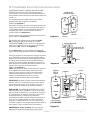
For Model:
RGD52
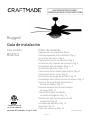
Rugged
page 1
Installation Guide
For
Damp Location
4007498

page 2
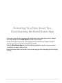
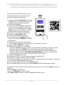
Activating Your New Smart Fan;
Downloading the Bond Home App
• Using your smart device, navigate to the application store (Apple App store or Google
Play), download the free Bond Home app and create account.
• Ensure the fan and receiver are receiving power from the house by supply using the
remote control to turn the fan and light ON and OFF.
• Open the Bond Home App on your smart device and follow step-by-step instructions
included in the app to add your fan.
• Enjoy fan features and functionality that you can only get from activating the fan through
the app.

page 3
SAFETY TIPS
WARNING: To reduce the risk of electrical shock, turn o the electricity to the fan at the main fuse box or circuit panel before you begin
the fan installation or before servicing the fan or installing accessories.
1. READ ALL INSTRUCTIONS AND SAFETY INFORMATION CAREFULLY BEFORE INSTALLING YOUR FAN AND SAVE THESE
INSTRUCTIONS.
CAUTION: To avoid personal injury, the use of gloves may be necessary while handling fan parts with sharp edges.
2. Make sure all electrical connections comply with Local Codes or Ordinances, the National Electrical Code, and ANSI/NFPA
70-1999. If you are unfamiliar with electrical wiring or if the house/building wires are dierent colors than those referred to in
the instructions, please use a qualied electrician.
3. Make sure you have a location selected for your fan that allows clear space for the blades to rotate, and at least seven (7) feet
(2.13 meters) of clearance between the oor and the fan blade tips. The fan should be mounted so that the tips of the blades
are at least thirty (30) inches (76 centimeters) from walls or other upright structures.
4. The outlet box and ceiling support joist used must be securely mounted, and capable of supporting at least
35 pounds (16 kilograms). The outlet box must be supported directly by the building structure. Use only CETL in Canada or
ETL in USA listed outlet boxes marked "FOR FAN SUPPORT."
WARNING: To reduce the risk of re, electrical shock, or personal injury, mount to the outlet box marked "Acceptable for Fan Support of
15.9 kg (35 lb) or less," and use the mounting screws provided with the outlet box. Most outlet boxes commonly used for the support of
lighting xtures are not acceptable for fan support and may need to be replaced. Consult a qualied electrician if in doubt.
WARNING: To reduce the risk of re, electrical shock, or personal injury, wire connectors provided with this fan are designed to accept
only one 12 gauge house wire and two lead wires from the fan. If your house wire is larger than 12 gauge or there is more than one
house wire to connect to the corresponding fan lead wires, consult an electrician for the proper size wire connectors to use.
5. Electrical diagrams are for reference only.
6. After installation is complete, check that all connections are absolutely secure.
7. After making electrical connections, spliced conductors should be turned upward and pushed carefully up into the outlet box.
The wires should be spread apart with the grounded conductor and the equipment-grounding conductor on opposite sides
of the outlet box.
WARNING: To reduce the risk of serious bodily injury, DO NOT use power tools to assemble any part of the fan, including the blades.
WARNING: To reduce the risk of re or electrical shock, do not use this fan with any solid state speed control device or control fan
speed with a full range dimmer switch. [Using a full range dimmer switch to control fan speed will cause a loud humming noise from
fan.] (Note: This fan is suitable for use with remote control.)
8. Do not operate the reverse switch until fan has come to a complete stop. [Note: If using remote control with reverse capability,
reverse fan blade direction only when on LOW speed.]
9. Do not insert anything between the fan blades while they are rotating.
WARNING: To avoid personal injury or damage to the fan and other items, be cautious when working around or cleaning the fan.
10. Do not use water or detergents when cleaning the fan or fan blades. A dry dust cloth or lightly dampened cloth will be suitable
for most cleaning.
WARNING: To reduce the risk of personal injury, use only parts provided with this fan. The use of parts OTHER than those provided
with this fan will void the warranty.
WARNING: This fan MUST be installed with the safety cable provided with the fan. Failure to use the safety cable provided may result in
personal injury, damage to the fan or damage to other property.
Modications not approved by the party responsible for compliance could void the user's authority to operate the equipment. [The
equipment refers to the remote and/or wall control and/or LED light kit.]
NOTE: This equipment has been tested and found to comply with the limits for a Class B digital device, pursuant to Part 15 of the FCC
Rules. These limits are designed to provide reasonable protection against harmful interference in a residential installation. This
equipment generates, uses and can radiate radio frequency energy and, if not installed and used in accordance with the instructions,
may cause harmful interference to radio communications. However, there is no guarantee that interference will not occur in a particular
installation. If this equipment does cause harmful interference to radio or television reception, which can be determined by turning the
equipment o and on, the user is encouraged to try to correct the interference by one or more of the following measures:
* Reorient or relocate the receiving antenna.
* Increase the separation between the equipment and receiver.
* Connect the equipment into an outlet on a circuit dierent from that to which the receiver is connected.
* Consult the dealer or an experienced radio/TV technician for help.
The remote and wall control complies with Part 15 of the FCC Rules. Operation is subject to the following two conditions: (1) this
remote and wall control may not cause harmful interference, (2) this remote and wall control must accept any interference received,
including interference that may cause undesired operation.
Distributed by:
Craftmade, 3901 S. 20th Avenue, DFW Airport, TX 75261; 1-800-486-4892.
NOTE: The important safety precautions and instructions appearing in the manual are not meant to cover all possible conditions and
situations that may occur. It must be understood that common sense and caution are necessary factors in the installation and
operation of this fan.

page 4
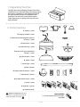
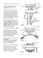
1. Unpacking Your Fan.
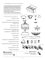
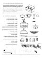
2. Parts Inventory.
Carefully open the packaging. Remove items from
Styrofoam inserts. Remove motor housing and place
on carpet or Styrofoam to avoid damage to nish.
Do not discard fan carton or Styrofoam inserts
should this fan need to be returned for repairs.
Check against parts inventory that all parts have
been included.
IMPORTANT REMINDER: You must
use the parts provided with this fan for
proper installation and safety.
a. canopy. 1 piece
b. hanging bracket.1 piece
c. downrod and hanging ball (with pin
and clip). 1 piece
d. yoke cover. 1 piece
e. motor housing. 1 piece
f. canopy cover (pre-attached to
canopy). 1 piece
g. light kit tter. 1 piece
h. shade. 1 piece
i. metal cage. 1 piece
j. blade. 6 pieces
k. remote control receiver. 1 piece
l. wall control. 2 pieces
m. remote control cover. 1 piece
n. plate. 1 piece
o. faceplate. 3 pieces
p. hardware packs
p
required bulbs:
2 x 5 watt medium base LED bulbs,
(included)
w/ wall controls
f
hi
j
e
ad
bc
g
mn
klo

page 5
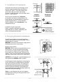
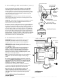
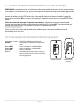
3. Installation Preparation.
4. Hanging Bracket Installation.
Vaulted ceiling
angle is not to
exceed 25 degrees.
downrod
installation ushmount
installation
7 feet
(2.13 m) (76 cm)
30
inches
12 ft. - 20 ft.
(3.66 m - 6.1 m)
(3.66 m - 6.1 m)
blade edge
To prevent personal injury and damage, ensure
that the hanging location allows the blades a
clearance of 7 feet (2.13m) from the oor and
30 in (76cm) from any wall or obstruction.
This fan is suitable for room sizes up to 400 square
feet (37.2 square meters).
Installation requires these tools:
Phillips screwdriver, athead screwdriver,
adjustable pliers or wrench, stepladder, wire
cutters, and rated electrical tape.
This fan can be mounted with a downrod
on a regular (no-slope) or vaulted ceiling. The
hanging length can be extended by purchasing
a longer downrod (0.5in. /1.27cm diameter).
Other installation, such as ushmount, is not
available for this fan.
12 ft. - 20 ft.
Turn o circuit breakers to current xture from
breaker panel and be sure operating light switch is
turned to the OFF position.
WARNING: Failure to disconnect power supply prior to
installation may result in serious injury.
Remove existing xture.
WARNING:When using an existing outlet box, be sure
the outlet box is securely attached to the building
structure and can support the full weight of the fan.
Ensure outlet box is clearly marked "Suitable for Fan
Support." If not, it must be replaced with an approved
outlet box. Failure to do so can result in serious injury.
CAUTION: Be sure outlet box is grounded properly and
that a ground wire (GREEN or bare) is present.
Install hanging bracket to outlet box using original
screws, spring washers and at washers provided
with new or original outlet box.* If installing on a
vaulted ceiling, face opening of hanging bracket
towards high point of ceiling. Arrange electrical
wiring around the back of the hanging bracket and
away from the bracket opening.
*Note: It is very important that you use the proper
hardware when installing the hanging bracket as this
will support the fan.
hanging bracket
spring washers
outlet box screws
at washers
ON
OFF
ON
OFF

page 6
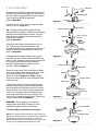
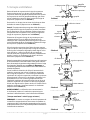
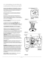
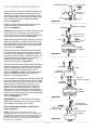
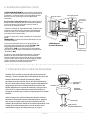
5. Fan Assembly.
NOTE: The important safety precautions and instructions
appearing in the manual are not meant to cover all possible
conditions and situations that may occur. It must be
understood that common sense and caution are necessary
factors in the installation and operation of this fan.
Remove hanging ball from downrod provided by
loosening set screw on hanging ball. Remove pin
and clip. Lower hanging ball and remove stop pin.
Then slide hanging ball o downrod.
[Refer to diagram 1.]
Loosen yoke set screws and nut at top of motor
housing. [Refer to diagram 2.]
Tip: To prepare for threading electrical wires
through downrod, apply a small piece of electrical
tape to the ends of the electrical wires--this will
keep the wires together when threading them
through the downrod.
[Refer to diagram 2.]
Determine the length of downrod you wish to
use. Thread safety cable and electrical wires
through threaded end of downrod and pull extra
wire slack from the upper end of the downrod.
[Refer to diagram 2.]
Thread downrod into the motor housing yoke
until holes for pin and clip in downrod align with
holes in yoke--make sure wires do not get twisted.
Re-insert pin and clip that were previously
removed. Tighten yoke set screws and nuts
securely. [Refer to diagram 2.]
Remove canopy cover from underside of canopy
by turning canopy cover counterclockwise. Slide
yoke cover, canopy cover and canopy over
downrod. [Refer to diagram 3.] (Note: Canopy
cover must be turned with shiny side toward the
motor housing.)
Thread safety cable and wires through hanging
ball; then slide hanging ball over downrod--the
top of the downrod should be noted as having a
set screw hole; use this hole when setting the set
screw. Insert stop pin into top of downrod and
raise hanging ball. Be sure stop pin aligns with
slots on the inside of the hanging ball. Tighten set
screw securely. [Refer to diagram 4.]
WARNING: Failure to tighten set screw (on
hanging ball) completely could result in the
fan becoming loose and possibly falling.
["Fan Assembly" continued on next page.]
downrod
electrical wiring
canopy
yoke cover
motor
housing
diagram 2
diagram 1
diagram 3
diagram 4
set screw hole
hanging ball
stop pin
downrod
electrical wiring
pin
clip
motor
housing
set screw
hanging ball
stop pin
pin
clip
safety cable
canopy cover
yoke set screw
and nut

page 7
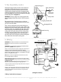
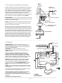
5. Fan Assembly. (cont.)
With the hanging bracket secured to the outlet box
and able to support the fan, you are now ready to
hang your fan. Grab the fan rmly with two hands.
Slide downrod through opening in hanging bracket
and let hanging ball rest on the hanging bracket. Turn
the hanging ball slot until it lines up with the hanging
bracket tab. [Refer to diagram 5.]
WARNING: Failure to align slot in hanging ball with
tab in hanging bracket may result in serious injury or
death.
Tip: Seek the help of another person to hold the
stepladder in place and to lift the fan up to you once
you are set on the ladder.
Find a secure attachment point (wood ceiling joist
highly recommended) and secure safety cable. It will
be necessary to use a heavy duty wood screw, washer
and lock washer (not supplied) with the safety cable
loop. If necessary, adjust the loop at the end of the
safety cable. The loop at the end of the safety cable
should just t over the threads on the wood screw.
Test safety cable by pulling on loose end with pliers. If
the safety cable slips, the loop must be adjusted tighter.
Extra cable slack can be left in ceiling area.
diagram 5
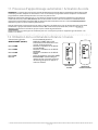
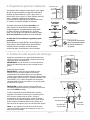
6. Wiring.
WARNING: Turn o circuit breakers to current xture from
breaker panel and be sure switch is turned to the OFF
position.
CAUTION: Be sure outlet box is properly grounded and that a
ground wire (GREEN or Bare) is present.
Make sure all electrical connections comply with Local Codes or
Ordinances and the National Electrical Code. If you are
unfamiliar with electrical wiring or if the house/building wires are
dierent colors than those referred to in the diagram to the right,
please use a qualied electrician.
Note: Excess lead wire length from the fan can be cut to the
desired length and then stripped.
When downrod is secured in place on the hanging bracket,
WIRE THE RECEIVER with wire connectors provided as shown
in diagram at right.
Tip: While you are wiring, keep in mind that wires must not
obstruct receiver from sliding into hanging bracket.
* Wrap each wire connector separately with electrical tape as
an extra safety measure.
Gently insert receiver (at side up) into hanging bracket and
carefully push taped wire connectors into outlet box. Allow
antenna from remote control receiver to hang outside of
hanging bracket.
["Wiring" continued on next page.]
(wiring for receiver)
ground (green
or bare)
white supply wire
black supply wire
black
black
white
blue
white
from receiver
black
AC IN L
AC IN N
white
white
ground (green
or bare)
from fan
from receiver
from ceiling
receiver
black
*
blue
antenna
motor housing
safety cable
hanging ball slot
wood ceiling joist
wood screw
and washer
safety cable loop
hanging bracket tab
Lorem ipsum

page 8
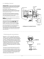
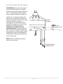
7. Canopy Assembly.
Locate 2 screws on underside of hanging bracket
and remove screw closest to the open end of the
hanging bracket. Partially loosen the other screw.
Lift canopy to hanging bracket. Place rounded part
of slotted hole in canopy over loosened screw in
hanging bracket and push up. Twist canopy to
lock. Re-insert screw that was removed and then
tighten both screws securely.
Slide canopy cover up to canopy, aligning rounded
part of slotted holes in canopy cover with
screwheads in bottom of canopy. Turn canopy
cover to the right (clockwise) until it stops.
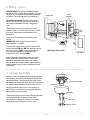
6. Wiring. (cont.)
(wiring for wall control)
black (OUT to fan)
green
black
(AC IN from
breaker box)
black
(TO POWER supply)
black
green/
bare
ground
outlet box wall
control
face-
plate
12V battery
wall plate
hanging bracket
screw
canopy
[PLEASE NOTE: Wall and/or handheld remote
control must be used for fan to operate. If you do
not wish to use the wall control, please proceed
to Section 7 to continue with fan installation.]
To install wall control, remove existing wall
switch. Wire one of the wall controls with wire
connectors provided as shown in diagram at
right.
*Wrap each wire connector separately with
electrical tape as an extra safety measure. Gently
push wires and taped wire connectors into
outlet box.
Install one 12-volt battery (included) in wall
control.
IMPORTANT: Wall control will not function
unless battery is installed.
Since this fan comes with a light kit, the dimmer
switch (labeled DIM and ON) has been pre-set to
the "ON" position (DIM). If you do not wish to
have dimming capability, please move the
switch to the "OFF" position (ON).
Select a faceplate (almond or white) and press
rmly onto front of wall control. Attach wall
control to outlet box and secure with screws
from original wall switch. Attach plate (included)
to wall control using 2 screws provided with the
wall control.
screw
canopy cover

page 9
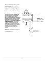
8. Blade Assembly.
WARNING: To reduce the risk of serious
bodily injury, DO NOT use power tools to
assemble the blades. If screws are
overtightened, blades may crack and
break.
Locate 15 blade attachment
screw/washers in hardware pack. Slide
blade through one of the narrow,
rectangular openings on motor housing,
aligning holes in blade with holes in
blade arm (located on the underside of
the motor housing)--refer to drawing at
right. Insert 3 blade attachment
screws/washers with ngers rst and
then tighten screws securely with a
Phillips screwdriver. Repeat procedure
for each remaining blade.
Note: Tighten blade attachment screws
twice a year.
motor housing
blade attachment
screws/washers
blade

page 10
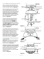
9. Light Kit Assembly.
Remove 1 screw from motor plate on
underside of motor housing and partially
loosen the other 2 screws.
Align slotted holes in shade with loosened
screws in motor plate, allowing molex
connectors to come through center hole in
shade. Twist shade to lock. Re-insert screw
that was previously removed and securely
tighten all 3 screws with a Phillips
screwdriver. [Refer to diagram 1.]
Remove 2 screws from underside of shade
and partially loosen the other 2 screws.
Connect WHITE wire from motor housing to
WHITE wire from light kit tter and BLUE (or
BLACK) wire from motor housing to BLUE
(or BLACK) wire from light kit tter. Make
sure molex connections snap together
completely. [Refer to diagram 1.]
Carefully arrange wiring within the shade.
Align
slotted holes in
light kit tter with
loosened screws in
shade.
Twist light kit
tter to lock.
Re-insert screws previously
removed and securely tighten all 4 screws
with a Phillips screwdriver.
[Refer to
diagram 1.]
Install 2 medium base 5 watt LED bulbs
(included).
Important: When you need to replace bulbs,
please allow bulb(s) and metal cage to cool
down before touching them.
[Refer to diagram 2.]
Locate 4 screws in hardware pack. Align
holes on top of metal cage with holes on
outer edge of shade. Secure metal cage with
the 4 screws.
Securely tighten all 4 screws
with a Phillips screwdriver.
[Refer to diagram 3.]
shade
light kit tter
motor plate
molex
connections
motor
housing
motor housing
bulb bulb
shade
metal cage
screwscrew
diagram 1
diagram 1
diagram 3
motor housing

page 11
10. Handheld Remote Control Assembly.
diagram 3
IN ORDER TO USE THE HANDHELD REMOTE
CONTROL, PLEASE CONTINUE WITH SECTION 10
for remote control assembly instructions. If you
have already installed the wall control but do not
wish to use the handheld remote control, please
proceed to Section 11.
Gently pull on remote control cover to separate
top and bottom parts. [Refer to diagram 1.]
In order to use wall control as a handheld
remote control, cut each wire on wall control
(that was not previously used)--use wire cutters
to cut o each wire as close to the wall control
as possible. [Refer to diagram 2.]
Install one 12-volt battery (included) in wall
control. [Refer to diagram 2.]
The dimmer switch (labeled DIM and ON) has
been pre-set to the "ON" position (DIM). If you
do not wish to have dimming capability, please
move the switch to the "OFF" position (ON).
[Refer to diagram 2.]
Attach black faceplate to front of wall control;
press down rmly. [Refer to diagram 3.]
Align holes in wall control with posts located on
inside of TOP part of remote control cover and
press together rmly. Place wall control into
BOTTOM part of remote control cover, aligning
posts in top of remote control cover with post
holes in the bottom. [Refer to diagram 3.]
(NOTE: Make sure to align narrower ends of
remote control cover before closing.) Squeeze
top and bottom of remote control cover
together until you hear a click at each end,
indicating that the remote control cover has
closed completely.
IMPORTANT: Store the remote control away
from excess heat or humidity. To prevent
damage to remote control, remove the battery if
remote control will not be used for long periods.
CAUTION: “DO NOT DISPOSE OF BATTERIES IN
FIRE, BATTERIES MAY EXPLODE OR LEAK.” - When
disposing of household alkaline batteries, it is
best to check with your local and state recycling
or household hazardous waste coordinators
concerning the specics of the program in your
area. You may also locate a recycling center by
calling 1-800-8-BATTERY or 1-877-2-RECYCLE or
visit www.epa.gov/epawaste/index.htm or
www.earth911.org for more information.
WARNING: Choking Hazard - Small parts. Keep
battery away from children.
(top)
(bottom)
remote
control
cover
diagram 1
diagram 2
dimmer
switch
wall control
wire
wire
wire
12V battery
DIM ON
DIM ON
wall
control
face-
plate
remote control
cover, BOTTOM
post
hole
post
hole
remote control
cover, TOP

page 12
11. Automated Learning Process./Activating Code.
12. Remote/Wall Control Operation.
wall control
CAUTION: The wall or handheld remote control can be programmed to multiple receivers or fans. If this is not
desired, turn wall switch o to any other programmable receiver or fan.
Restore electrical power and then, if using wall control, set slider switch on wall control to the ON position.
Within 60 seconds of turning on the wall control, press and hold the fan OFF button on the wall control for
5 seconds or until light blinks twice.
Turn power o again for at least 5 seconds and then turn power back on. Within 60 seconds of restoring
the power, press and hold the fan OFF button on the front of the handheld remote control for 5 seconds or
until light blinks twice.
Test the light and fan functions to conrm the learning process is complete--see Section 14 .
handheld
remote control
ON/OFF slider switch - turns wall control ON or OFF
(switch not functional on handheld
remote)
HIGH button - turns fan to HIGH speed
MED button - turns fan to MEDIUM speed
LOW button - turns fan to LOW speed
OFF button - turns fan OFF
L button - turns light kit ON/OFF when pressed once;
dims light kit when pressed and help
down.

page 13
13. Smart Ceiling Fan Wi-Fi Control (Optional).
Without Wi-Fi activation, you will not enjoy the expanded features and functionality
of your ceiling fan: Breeze speed setting, Creating Schedules and Voice Activation.
To enjoy all the potential of your new device, refer
to the following steps to complete Smart setup.
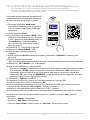
1. Download the Bond Home App, available on
the Google Play Store and Apple App Store, or
use the QR code to download the app.
2. Open the Bond application.
3. If you already have a Bond account, simply log
in and continue to Step 4. If you do not have a
Bond account, press “Create Account” and
enter your name, email and create a password.
4. Select “+” to add a device.
5. Select “Smart By Bond” (SBB).
6. Select this smart ceiling fan.
7. Once the Bond application connects to the fan,
select “CONTINUE” to proceed.
8. Test the fan functions:
- You have the option to disable the light
function if your fan does not have a light.
9. Select “YES, IT WORKS.”
10. Specic information about your fan:
-Select “Location” and choose from one of the predened entries or add your own by selecting
“OTHER”. When nished, select “Save”.
- Select device name and enter the name for your device. When nished, select “OK” to save.
PLEASE NOTE: This name will be used for integrations so a simple, easy-to-remember name is best.
11. Select “Continue”.
12. Select the Wi-Fi network you would like to connect the SBB to.
13. Enter the Wi-Fi password and select “OK”.
14. If there is an issue with the connection or wrong password is entered, you will receive an error message.
Select “OK, I’ve Got It”.
15. Once the connection is made, select “DONE”.
16. If the SBB fan is not displayed in the Bond application, swipe down to refresh.
For assistance at any time during this process, go to the “Help” section of the app:
- Tap on “Settings”
- Tap on “Help Center”
- Choose “Open a Ticket” or “Live Chat”

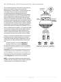
14. Testing Your Fan.
motor
housing
It is recommended that you test fan before
nalizing installation. Restore power from circuit
box and light switch (if applicable). Test wall
control (optional installation) by locating ON/OFF
slider switch on wall control, then set to the ON
position. Test light and then test fan speeds. Next,
locate handheld remote control. Test the light
ON/OFF function by pressing the L button; Test
fan speeds with the dierent fan speed buttons. If
the wall and/or handheld remote control operates
all of the functions of the fan, battery (batteries)
has (have) been installed correctly. If the wall
and/or handheld remote control do (does) not
operate all of the fan/light functions, refer to
"Troubleshooting" section to solve any issues
before contacting Customer Service.
Turn fan completely o before moving the
reverse switch (located on top of motor housing).
Set reverse switch to recirculate air depending on
the season:
- LEFT position in summer (diagram 1)
- RIGHT position in winter (diagram 2)
A ceiling fan will allow you to raise your
thermostat setting in summer and lower your
thermostat setting in winter without feeling a
dierence in your comfort.
Important: Reverse switch must be set either
completely LEFT or completely RIGHT for fan to
function. If the reverse switch is set in the middle
position (diagram 3), fan will not operate.
NOTE: If the wall control/handheld remote
control interferes with other appliances, turn
power o rst and then go back to the
instructions in Section 11.
diagram 1 diagram 2 diagram 3
reverse
switch
page 14

Troubleshooting. Warranty.
Parts Replacement.
WARNING: Failure to disconnect power supply
prior to troubleshooting any wiring issues may
result in serious injury.
page 15
JMLI2109
For parts and information, please refer to
"Parts Inventory" on page 4.
Craftmade Customer Support:
1-800-486-4892
www.craftmade.com
CRAFTMADE™ LIFETIME LIMITED WARRANTY:
CRAFTMADE warrants this fan to the original household
purchaser for indoor use under the following provisions:
1-YEAR WARRANTY: CRAFTMADE will replace or repair any
fan which has faulty performance due to a defect in
material or workmanship. Contact Craftmade Customer
Service at 1-800-486-4892 to arrange for return of fan.
Return fan, shipping prepaid, to Craftmade. We will repair
or ship you a replacement fan, and we will pay the return
shipping cost.
5-YEAR WARRANTY: CRAFTMADE will repair or replace, at
no charge to the original purchaser, any fan motor that
fails to operate satisfactorily when failure results from
normal use.
RETURN FAN MOTOR ONLY, shipping prepaid, to Craftmade
Industries. We will repair or ship purchaser a replacement
motor and Craftmade will pay the return shipping cost.
6-YEAR to LIFETIME LIMITED WARRANTY: CRAFTMADE will
repair the fan, at no charge for labor only to the original
purchaser, if the fan motor fails to operate satisfactorily
when failure results from normal use. Parts used in the
repair will be billed to the purchaser at prevailing prices at
time of repair.
The purchaser shall be responsible for all costs incurred
in the removal, reinstallation and shipping of the product
for repairs.
This warranty does not apply when damage from
mechanical, physical, electrical or water abuse results in
causing the malfunction. Deterioration of nishes or other
parts due to time or exposure to salt air is specically
exempted under this warranty.
Neither Craftmade nor the manufacturer will assume any
liability resulting from improper installation or use of this
product. In no case shall the company be liable for any
consequential damages for breach of this, or any other
warranty expressed or implied whatsoever. This limitation
as to consequential damages shall not apply in states
where prohibited.
Problem: Fan fails to operate.
Solutions:
1. Check power to wall switch/wall control.
2.Verify that wall control (optional use) is wired
properly.
3. Check to be sure fan is wired properly.
4. Learning process between fan, handheld
remote control and, if applicable, wall control
may not have been successful and code was not
activated. Turn o power and repeat instructions
in Section 11 (page 12).
5. Check that red light on handheld remote
control turns on when a button is pressed
indicating that the battery is good.
6. Verify that reverse switch is set completely in
either direction.
Problem: Light kit not lighting.
Solutions:
1. Check wall switch to fan/wall control.
2. Check that bulbs are installed correctly.
3. Check to be sure wires in canopy are wired
properly.
4. Learning process between fan, handheld
remote control and, if applicable, wall control
may not have been successful and code was not
activated. Turn o power and repeat instructions
in Section 11 (page 12).
5. Replace defective bulbs with same type of bulb.
Problem: Fan and light fail to operate with
remote control and/or wall control.
Solutions:
1. Check battery power to handheld remote
control and/or wall control.
2. Learning process between fan, handheld
remote control and, if applicable, wall control
may not have been successful and code was not
activated. Turn o power and repeat instructions
in Section 11 (page 12).
Problem: Fan wobbles.
Solutions:
1. Use the balancing kit provided in one of the
hardware packs. If no blade balancing kit is
provided, please call Customer
Support,1-800-486-4892, to request one.
2. Check to be sure set screw(s) on motor housing
yoke is (are) tightened securely.
3. Check to be sure set screw on hanging ball is
tightened securely.

Rugged
page 1
LISEZ CES INSTRUCTIONS ET
CONSERVEZ-LES POUR USAGE FUTUR
Guide d'installation
Pour le modèle :
RGD52
Table des Matières :
Conseils de sécurité. p. 3
Déballage de votre ventilateur. p. 4
Contenu de l’emballage. p. 4
Préparation de l'installation. p. 5
Installation du support de suspension. p. 5
Groupe ventilateur. pgs. 6 - 7
Câblage. pgs. 7 - 8
Montage de la garniture. p. 8
Fixation des pales. p. 9
Assemblage du Kit d'éclairage. p.10
Assemblage du module de commande à
distance portatif. p. 11
Processus d'apprentissage automatisé /
Activation du code. p. 12
Utilisation de la commande à distance /
murale. p. 12
Contrôle Wi-Fi du ventilateur de
plafond intelligent. p.13
Tester votre ventilateur. pg. 14
Dépannage. p. 15
Garantie. p. 15
Remplacement des pièces. p. 15
IMPRIMÉ EN CHINE
poids net du ventilateur : 9,9 kg (21,83 lb)
APPROUVÉ POUR
MILIEU HUMIDE
4007498

page 2
Téléchargez l’application Bond Home;
Activez votre ventilateur intelligent
• Avec votre appareil intelligent, accédez au magasin d'applications (Apple App Store ou
Google Play), téléchargez l’application gratuite Bond Home et créez un compte.
• Assurez-vous que le ventilateur et le récepteur soient alimentés par le réseau de
l’habitation en ALLUMANT et en ÉTEIGNANT le ventilateur et l’éclairage à l'aide de la
télécommande.
• Lancez l’application Bond Home sur votre appareil intelligent et suivez les instructions
étape par étape incluses dans l'application pour ajouter votre ventilateur.
• Protez des capacités et des fonctionnalités du ventilateur que vous ne pouvez obtenir
qu'en l’activant via l'application.

page 3
AVERTISSEMENT : An de réduire le danger d'électrocution, coupez l'alimentation électrique du ventilateur au niveau du disjoncteur, de l'armoire ou du
panneau électrique principal avant de commencer l'installation du ventilateur ou avant d'entreprendre des travaux de réparation ou avant d'installer des
accessoires.
1. LISEZ ATTENTIVEMENT TOUTES LES INSTRUCTIONS ET LES INFORMATIONS DE SÉCURITÉ AVANT D'INSTALLER VOTRE VENTILATEUR ET
CONSERVEZ CES INSTRUCTIONS.
ATTENTION : Pour éviter toute blessure corporelle, il peut s'avérer nécessaire de porter des gants lors de la manutention de pièces de ventilateur qui
présentent des bords coupants.
2. Assurez-vous que tous les branchements électriques sont conformes aux Codes et Ordonnances locales, au Code Électrique national, et à
l'ANSI/NFPA 70-1999. Si vous n'êtes pas familier avec le câblage électrique ou si les câbles de la maison/bâtiment sont de couleurs diérentes
de celles auxquelles il est fait référence dans ces instructions, alors veuillez faire appel à un électricien qualié.
3. Assurez-vous que l'endroit que vous avez choisi pour votre ventilateur présente un espace susant pour permettre aux pales de tourner librement
et une distance d'au moins 2,13 mètres (7 pieds) entre le sol et les extrémités des pales du ventilateur. Le ventilateur doit être monté de telle
sorte qu'il y ait un espace d'au moins 76 centimètres (30 pouces) entre les extrémités des pales et les murs ou autres structures verticales.
4. La boîte de sortie et la poutre de support du plafond doivent être solidement arrimées et capables de soutenir une charge d'au moins 35 livres
(16 kilogrammes). La boîte de sortie doit être montée directement sur une structure porteuse du bâtiment. Veillez à n'utiliser que des boîtes
de sortie approuvées CETL (Canada) ou ETL (USA) portant l'inscription « ADAPTÉ POUR SOUTENIR UN VENTILATEUR ».
AVERTISSEMENT : An de minimiser les risques d'incendie, d'électrocution ou de blessures corporelles, montez sur une boîte de sortie portant la
mention « Convient pour soutenir un ventilateur de 15,9 kg (35 Lb) maximum » [« Acceptable for Fan Support of 15.9 kg (35 lb) or less »] et utilisez les vis
de xation fournies avec la boîte de sortie. La plupart des boîtes de sortie communément utilisées pour soutenir des luminaires ne sont pas adéquates
pour soutenir un ventilateur et devront éventuellement être remplacées. Consultez un électricien qualié en cas de doute.
AVERTISSEMENT : Pour réduire les risques d'incendie, d'électrocution ou de blessures corporelles, les connecteurs de ls fournis avec ce ventilateur sont
conçus pour n'accepter qu'un l résidentiel de calibre 12 et deux ls en provenance du ventilateur. Si le l résidentiel est d'un calibre supérieur à 12 ou
s'il y a plus d'un l résidentiel à connecter aux ls correspondants du ventilateur, consulter un électricien pour savoir quelle taille de connecteurs de ls
utiliser.
5. Les schémas électriques ne sont fournis que pour référence.
6. Lorsque l'installation est terminée, vériez que toutes les connexions sont correctement et solidement eectuées.
7. Après avoir eectué des branchements électriques, les ls ainsi raccordés doivent être tournés vers le haut et insérés dans la boîte de sortie avec
précaution. Les ls doivent être séparés avec le l de terre et le l de raccordement à la terre de l'unité positionnés sur les côtés opposés de la
boîte de sortie.
AVERTISSEMENT : An de réduire le risque de blessures corporelles graves, NE PAS utiliser d'outils électriques pour assembler n’importe quelle pièce du
ventilateur, y compris les pales.
AVERTISSEMENT : An de réduire le danger d'électrocution ou d'incendie, ne pas utiliser ce ventilateur avec un variateur de vitesse à circuit intégré ou
régler la vitesse à l'aide d'un interrupteur à variateur intégral. [Le fait d’utiliser un interrupteur à variateur intégral pour contrôler la vitesse du ventilateur
occasionnera un vrombissement sourd en provenance du ventilateur.]
8. Ne pas actionner le commutateur d'inversion avant que le ventilateur ne soit parvenu à un arrêt complet. Remarque : Si vous utilisez une
commande à distance équipée de la fonction inversion, n’inverser le sens de rotation des pales qu’en vitesse LENTE.]
9. Ne rien insérer entre les pales du ventilateur lorsqu'elles sont en mouvement.
AVERTISSEMENT : Pour éviter toute blessure corporelle ou dommage au ventilateur et autres éléments, faites preuve de prudence lorsque vous
travaillez autour du ventilateur ou lorsque vous le nettoyez.
10. Ne pas utiliser d'eau ou de détergents pour nettoyer le ventilateur ou les pales du ventilateur. Un chion sec ou légèrement humide se prête
bien à la plupart des tâches de nettoyage.
AVERTISSEMENT : An de réduire le risque de blessures corporelles, n'utiliser que les pièces livrées avec ce ventilateur. L'utilisation de toutes pièces
AUTRES que celles fournies avec ce ventilateur annulera la garantie.
AVERTISSEMENT : Ce ventilateur DOIT être installé à l’aide du câble de sécurité fourni avec le ventilateur. Ne pas utiliser le câble de sécurité fourni peut entraîner
des blessures corporelles graves, des dommages au ventilateur ou d’autres dommages matériels.
Toutes les modications qui n’ont pas fait l’objet d’une autorisation expresse de la partie responsable de la conformité peuvent annuler la faculté de
l’usager d’utiliser l’appareil. [L’équipement fait référence à la télécommande et/ou la commande murale et/ou le kit d’éclairage DEL.]
REMARQUE : Après avoir subi les tests réglementaires, le présent équipement a satisfait aux exigences requises pour les dispositifs numériques de Classe
B, conformément aux Règles de la FCC Partie 15. Ces exigences sont destinées à orir une protection raisonnable contres les interférences néfastes dans
le cadre des installations résidentielles. Le présent équipement génère, utilise et peut émettre des fréquences radioélectriques et, s'il n'est pas installé et
utilisé conformément aux instructions, peut causer des interférences néfastes aux communications radio. Toutefois, il n’existe aucune certitude que des
interférences se produiront dans une installation spécique. S’il s’avère que le présent équipement produit eectivement des interférences néfastes à la
réception radio ou télévision, qui peut être déterminée en mettant en marche puis en arrêtant l'équipement, il est recommandé à l'usager d'essayer de
corriger le problème d’interférence en suivant une ou plusieurs des démarches suivantes :
* réorienter ou déplacer l’antenne de réception.
* augmenter la distance qui sépare l’équipement du récepteur.
* brancher l'équipement sur une source électrique raccordée à un circuit diérent de celui sur lequel le récepteur est branché.
* Consultez et cherchez l’assistance d’un revendeur ou d’un technicien radio/TV expérimenté.
La télécommande et la commande murale est conforme à la Section 15 de la Réglementation de la FCC. L'utilisation en est soumise aux deux conditions
suivantes : (1) la télécommande et la commande murale ne doit pas causer d'interférences nuisibles, (2) la télécommande et la commande murale doit
accepter toutes les interférences reçues, y compris les interférences qui peuvent causer un fonctionnement non souhaité.
Distribué par : Craftmade, 3901 S. 20th Avenue, DFW Airport, TX 75261; 1800 486-4892
REMARQUE : Les précautions de sécurité et les instructions importantes gurant dans le manuel ne sauraient prévoir toutes les conditions et situations
possibles. Il est entendu que le bon sens et la prudence sont de rigueur pour l'installation et l'utilisation de ce ventilateur.
CONSEILS DE SÉCURITÉ.

page 4
a. garniture. 1 pièce
b. support de suspension. 1 pièce
c. tige et boule de suspension (avec goupille et
attache). 1 pièce
d. couvre étrier. 1 pièce
e. carter moteur. 1 pièce
f. couvercle de garniture (pré-monté sur la
garniture). 1 pièce
g. adaptateur de kit d’éclairage. 1 pièce
h. abat-jour. 1 pièce
i. cage métallique
j. pale. 6 pièces
k. récepteur de commande à distance. 1 pièce
l. commade murale. 2 pièces
m. couvercle de commande à distance. 1 pièce
n. plaque. 1 pièce
o. plaque décorative. 3 pièces
p. paquets de quincaillerie
1. Déballage de votre ventilateur.
Ouvrir l'emballage avec précaution. Retirer toutes
les pièces des inserts en polystyrène. Retirer le
carter moteur et le placer sur une pièce de tapis
ou de polystyrène an de ne pas endommager la
nition. Ne pas jeter le carton ou les pièces de
polystyrène pour le cas où le ventilateur devrait
être renvoyé pour réparation.
Vérier à l'aide de la liste des pièces pour vous
assurer que toutes les pièces sont bien présentes.
2. Inventaire des pièces.
RAPPEL IMPORTANT :
Vous devez utiliser les pièces
fournies avec ce ventilateur pour
une installation correcte et sûre.
avec les commandes
murales
p
f
hi
j
e
ad
bc
g
mn
klo
ampoules requises:
2 ampoules DEL douille moyenne
5 watts (incluses)

page 5
3. Préparation à l’installation.
Installation avec
tige de suspension Installation
en plafonnier
bord de pale
2,13 m
(7 pieds)
76 cm
(30
pouces)
Pour éviter les blessures corporelles et les
dommages, assurez-vous que l’emplacement de
suspension accorde aux pales un dégagement de
2,13 m (7 pi) du sol et de 76 cm (30 po) de tout mur
ou obstruction.
Ce ventilateur convient aux pièces mesurant jusqu’à
37,2 mètres carrés (400 pieds carrés).
Ce ventilateur peut être installé avec une tige de
suspension sur un plafond ordinaire (sans pente) ou
en voûte. La longueur de suspension peut être
allongée en achetant une tige de suspension plus
longue (1,27 cm/0,5 po de diamètre). Une autre
installation, telle qu’en plafonnier, n’est pas possible
pour ce ventilateur.
L’installation requiert les outils suivants :
Tournevis cruciforme, tournevis à tête plate, pince
réglable ou clé à molette, escabeau, coupe-ls et
ruban isolant homologué.
3,66 m à 6,1 m
(12 pi à 20 pi)
3,66 m à 6,1m
(12 pi à 20 pi)
L’angle du plafond
en voûte ne doit pas
dépasser 25 degrés.
ON
OFF
ON
OFF
4. Installation du support de suspension.
Coupez l'alimentation électrique du luminaire en place au niveau
des coupe-circuits du panneau électrique et assurez-vous que
l'interrupteur qui en contrôle le fonctionnement est bien en
position ARRÊT.
AVERTISSEMENT : Le fait de ne pas débrancher l'alimentation
électrique avant l'installation peut causer des blessures graves.
Déposez l'appareil existant.
AVERTISSEMENT : Dans le cas de l'utilisation d'une boîte de sortie
existante, veillez à s'assurer que la boîte de sortie est solidement
xée à la structure de la construction et qu'elle peut supporter la
totalité du poids du ventilateur. Vériez que la mention "Adapté
pour soutenir un ventilateur" ("FOR FAN SUPPORT") soit clairement
indiquée sur la boîte de sortie. Si tel n'est pas le cas, elle doit être
remplacée par une boîte de sortie approuvée. Tout défaut à cette
règle peut résulter en des blessures graves.
ATTENTION : Assurez-vous que la boîte de sortie est correctement
reliée à la terre et qu'il existe bien un l de terre (VERT ou dénudé).
Fixez le support de suspension sur la boîte de sortie à l'aide des
vis, rondelles fendues et rondelles plates originales fournies avec
une nouvelle boîte de sortie ou la boîte de sortie originale.* En
cas d'installation dans un endroit avec un plafond voûté, il y a
lieu de veiller à toujours diriger l'ouverture du support de
suspension vers le point haut du plafond. Disposez le câblage
derrière le support de suspension de telle sorte qu'il soit à l'écart
de l'ouverture du support.
*Remarque : Il est très important d'utiliser les pièces de montage
prévues à cet eet lorsque vous installez le support de suspension du
fait que celles-ci seront appelées à supporter la charge du
ventilateur.
support de
suspension
vis de la boîte
de sortie
rondelles plates
rondelles
fendues
La page charge ...
La page charge ...
La page charge ...
La page charge ...
La page charge ...
La page charge ...
La page charge ...
La page charge ...
La page charge ...
La page charge ...
La page charge ...
La page charge ...
La page charge ...
La page charge ...
La page charge ...
La page charge ...
La page charge ...
La page charge ...
La page charge ...
La page charge ...
La page charge ...
La page charge ...
La page charge ...
La page charge ...
La page charge ...
-
 1
1
-
 2
2
-
 3
3
-
 4
4
-
 5
5
-
 6
6
-
 7
7
-
 8
8
-
 9
9
-
 10
10
-
 11
11
-
 12
12
-
 13
13
-
 14
14
-
 15
15
-
 16
16
-
 17
17
-
 18
18
-
 19
19
-
 20
20
-
 21
21
-
 22
22
-
 23
23
-
 24
24
-
 25
25
-
 26
26
-
 27
27
-
 28
28
-
 29
29
-
 30
30
-
 31
31
-
 32
32
-
 33
33
-
 34
34
-
 35
35
-
 36
36
-
 37
37
-
 38
38
-
 39
39
-
 40
40
-
 41
41
-
 42
42
-
 43
43
-
 44
44
-
 45
45


Craftmade RGD52 Guide d'installation
- Catégorie
- Ventilateurs ménagers
- Taper
- Guide d'installation
dans d''autres langues
- English: Craftmade RGD52 Installation guide
- español: Craftmade RGD52 Guía de instalación
Documents connexes

Autres documents
-
Modern Forms FR-W2006 Zephyr 62 Mode d'emploi
-
-
-
-
-
-
 Hinkley 903752 52 Inch Chisel Ceiling Fan Manuel utilisateur
-
 Hinkley 903760 60 Inch Chisel Ceiling Fan Manuel utilisateur
-
-
Lightolier IHB Series Decorative High Bay Manuel utilisateur

