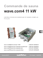
Sentiotec wave.com4 11kW Manuel utilisateur
- Taper
- Manuel utilisateur

EN
DE
FR
IT
INSTRUCTIONS FOR INSTALLATION AND USE
English
NL
SV
FI
RU
Version 03/21 Ident no. 1-050-755
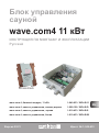
WC4-B-11
WC4-B-D/W/S
Sauna controller
wave.com4 11 kW
wave.com 4 basic module 11 kW 1-049-633 / WC4-B-11
wave.com 4 control unit, dark wood 1-008-128 / WC4-B-D
wave.com 4 control unit, black 1-010-433 / WC4-B-S
wave.com 4 control unit, white 1-010-433 / WC4-B-W

Table of Contents
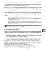
1. About this instruction manual 5
2. Important information for your safety 6
2.1. Intended use 6
2.2. Safety information for the installer 7
2.3. Safety information for the user 8
3. Product description 9
3.1. Scope of delivery 9
3.2. Not supplied 9
3.3. Optional accessories 9
3.4. Product features 10
3.5. Sauna operating modes 11
3.6. Sensor operating modes 11
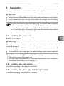
4. Installation 13
4.1. Installing the power unit 13
4.2. Installing the main switch 13
4.3. Installing the cabin light and the light switch 13
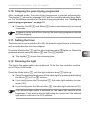
4.4. Installing the expansion board (optional) 14
4.5. Installing the control unit 14
4.6. Installing the heater sensor F1 with overheat cut-out 15
4.8. Installing the bench sensor F2 (optional) 16
4.9. Installing the humidity sensor WC4-H-H (optional) 16
4.7. Installing the humidity/temperature sensor FTS2 (optional) 16
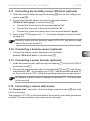
5. Electrical connection 17
5.1. Connecting the power supply cable and heater 18
5.2. Connecting the evaporator (optional) 18
5.3. Connecting the control unit 18

EN
5.4. Connecting an external main switch 19
5.5. Connecting the light 19
5.6. Connecting an external light switch 19
5.7. Connecting a fan (optional) 19
5.8. Connecting the heater sensor F1 20
5.9. Connecting the humidity/temperature sensor FTS2 (optional) 20
5.10. Connecting the bench sensor F2 (optional) 20
5.11. Connecting the humidity sensor WC4-H-H (optional) 21
5.12. Connecting a dummy sensor (optional) 21
5.13. Connecting a power booster (optional) 21
5.14. Connecting a remote start device 21
5.15. Finishing the installation 22
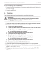
6. Testing 22
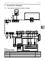
7. Connection diagram 23
7.1. Connection diagram of basic module 23
7.2. Connection diagram for the expansion board (optional) 24
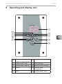
8. Operating and display unit 25
9. Operation 26
9.1. Switching on 26
9.2. Setting the heating time 26
9.3. Setting the language 26
9.4. Switching on the light (cleaning light) 27
9.5. Selecting the operating mode 27
9.6. Starting FIN sauna mode 27
9.7. SwitchingoFIN sauna mode 28
9.8. Starting combined HUM mode 28
9.9. SwitchingocombinedHUM mode 28
9.10. Stopping the post-drying programme 29

9.11. Setting the timer 29
9.12. Dimming the light 29
9.13. Setting the preset time 30
9.14. ECO mode 30
9.15. Activating standby for remote operation 31
9.16. Remote start release 31
9.17. Activating an additional control unit 32
9.18. Setting the acoustic signal 32
9.19. Activating the rolling display 33
9.20. Setting the post-drying programme 33
9.21.Switchingothesaunacontroller 34
10. Cleaning and maintenance 34
10.1. Cleaning 34
10.2. Maintenance 34
11. Disposal 34
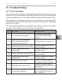
12. Troubleshooting 35
12.1. Error messages 35
12.2. Fuses 36
12.3. Temperature correction 36
13. Technical data 37

EN
Instructions for installation and use p. 5/38
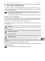
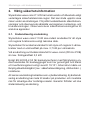
1. About this instruction manual
Read these installation and operating instructions carefully and keep them within
reach of the sauna controller. This ensures that you can refer to information on
safety and operation at any time.
Symbols used for warning notices
In these instructions for installation and use, a warning notice located next to
an activity indicates that this activity poses a risk. Always observe the warning
notices. This prevents damage to property and injuries, which in the worst case
may be fatal.
The warning notices contain keywords, which have the following meanings:
DANGER!
Serious or fatal injury will occur if this warning notice is not observed.
WARNING!
Serious or fatal injury can occur if this warning notice is not observed.
CAUTION!
Minor injuries can occur if this warning notice is not observed.
ATTENTION!
This keyword is a warning that damage to property can occur.
Other symbols
This symbol indicates tips and useful information.
These installation and operating instructions can also be found in the down-
loads section of our website: www.sentiotec.com/downloads.

Instructions for installation and use p. 6/38
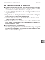
2. Important information for your safety
The wave.com4 11 kW sauna controller has been manufactured
according to the applicable safety regulations. However, hazards
may arise during use. You should therefore adhere to the following
safetyinformationandthespecicwarningsintheinstallationand
operating instructions. Also observe the safety information for the
devices connected.
2.1. Intended use
The wave.com4 11 kW sauna controller is designed solely for oper-
ating and controlling the functions described in the technical data.
The sauna controller may only be used for operating and controlling
three heating circuits with a maximum output of 3.7 kW per heating
circuit.
When using the optional wave.com4 expansion board (WC4-H-PCB),
the maximum evaporator output is 3.0 kW.
According to EN 60335-2-53 sauna remote control units may only be
used to regulate and control a sauna heater that passes the cover test
according to paragraph 19.101. Alternatively, an appropriate safety
measure (e.g.: safety shutdown, door contact...) must be installed.
Any use exceeding this scope is considered improper use. Improper
use can result in damage to the product, severe injuries or death.
The warranty is void if the device is not used as intended.

EN
Instructions for installation and use p. 7/38
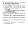
2.2. Safety information for the installer
● Theelectricalconnectionmayonlybeperformedbyaqualied
electricianorsimilarlyqualiedperson.Pleasenotethatinthe
event of a guarantee claim, a copy of the invoice issued by
the electrician performing the work must be presented.
●Work on the sauna controller may only be performed when the
power has been disconnected.
●A fully disconnecting all-pole isolating device compliant with
overvoltagecategoryIIImustbettedonsite.
●The power unit of the wave.com4 11 kW (WC4-B-11) must be
installed in accordance with the technical data.
●The control unit can be installed inside or outside the sauna,
however it must be mounted according to the installation and
operating manual provided.
●Also comply with the regulations applicable at the installation
location.
●For your own safety, consult your supplier in the event of prob-
lemsthatarenotexplainedinsucientdetailintheinstallation
instructions.

Instructions for installation and use p. 8/38
2.3. Safety information for the user
●The sauna controller must not be used by children under 8 years
of age.
●The sauna controller may be used by children over 8 years of
age, by persons with limited psychological, sensory or mental
capabilities or by persons with lack of experience/knowledge,
but only if:
– They are supervised.
– They have been shown how to use the device safely and
are aware of the hazards that could occur.
●Children must not play with the sauna controller.
●Children under 14 years of age may only clean the sauna con-
troller if they are supervised.
● Forhealthreasons,donotusethesaunawhenundertheinu-
ence of alcohol, medication or drugs.
● Makesurethatnoammableobjectshavebeenplacedonthe
sauna heater before the sauna controller is switched on.
● Makesurethatnoammableobjectshavebeenplacedonthe
sauna heater before activating the preset time function or the
standby mode for remote start.
●For your own safety, consult your supplier in the event of problems
thatarenotdescribedinsucientdetailintheuserinstructions.

EN
Instructions for installation and use p. 9/38
3. Product description
The wave.com4 11 kW is a two-piece sauna controller. In order to function, a basic
module with power unit (WC4-B-11), a control unit (WC4-B-S, WC4-B-D or WC4-
B-W) and a heater sensor (WC4-B-F1D or WC4-B-F1H) are always required.
3.1. Scope of delivery
●Power unit (1-049-633 / WC4-B-11)
●Installation and operation manual
3.2. Not supplied
●Main switch (standard 230 V switch)
●Light switch (standard 230 V switch)
●Dark wood control unit (1-008-128 / WC4-B-D)
or black control unit (1-010-389 / WC4-B-S)
or white control unit (1-010-437 / WC4-B-W)
●Light wood heater sensor (1-013-651 / WC4-B-F1H), 5 m sensor cables
or dark wood heater sensor (1-003-479 / WC4-B-F1D), 5 m sensor cables
3.3. Optional accessories
●Expansion board for humidity, bench sensor (1-003-472 / WC4-H-PCB)
●Dark wood WC4 bench sensor (1-003-295/WC4-H-F2D), 5 m sensor cables
●Light wood WC4 bench sensor (1-013-662/WC4-H-F2H), 5 m sensor cables
●Dark wood humidity sensor (1-003-364 / WC4-H-HD), 5 m sensor cables
●Light wood humidity sensor (1-013-669 / WC4-H-HH), 5 m sensor cables
●Humidity/temperature sensor (1-010-081/O-FTS2), 6 m sensor cables
●Dark wood sensor housing for FTS2 (1-041-521 / SC-FTS2-D)
●Light wood sensor housing for FTS2 (1-041-520 / SC-FTS2-D)
●Y-adapter RJ10 4-pin (1-028-167 / WC4-C-ADY)
●Power booster (1-008-779 / O-S2-18, 1-009-280 / O-S2-30)
●Safety shutdown (SFE-xxxxx)
●Remote start system (1-051-003 / FS-SY)
●Door sensor system (1-052-722 / SAB00102)

Instructions for installation and use p. 10/38
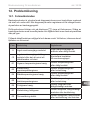
3.4. Product features
The wave.com4 11 kW sauna controller features the following functions:
●Regulation of sauna heaters with a heating output of up to 11 kW.
●When an expansion board is installed, regulation of combined heaters with
a heating output of up to 11 kW and evaporator output of up to 3 kW.
●When a power booster is installed, the maximum power rating of 11 kW can
be increased.
●Option to connect external main switch
●Option to connect external light switch
●Switching and dimming a cabin light (up to 100 W bulb)
●Fan regulation (up to 100 W)
●Automatic heating time limit
The sauna controller shuts down automatically for safety reasons after the
maximum heating time (1 to 12 hours).
●Preset time function (1 to 24 hours)
●Acoustic signal for time interval (e.g: time to pour water on stones)
●Post-drying program
After operation in combined mode, the post-drying program starts automatically
to prevent mould or rot from forming in the sauna cabin. (3 setting options).
●Remote start function
●Eco mode
Eco mode ensures that the cabin temperature is the same after a break
(20, 40, 60 minutes).
●Overheat cut-out
The overheat cut-out is installed in the housing for the heater sensor. If a de-
fect causes the sauna heater to continue heating after reaching the preferred
temperature,theoverheatcut-outswitchesthesaunaheateroatatemper-
ature of around 139 °C.

EN
Instructions for installation and use p. 11/38
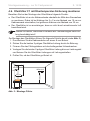
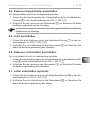
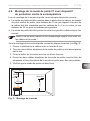
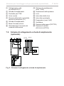
3.5. Sauna operating modes
Sauna mode
Dry heat is provided in sauna mode. The temperature in the cabin is high (80 to
100 °C). The humidity is low (no more than 10%).
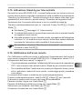
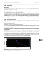
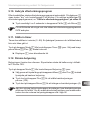
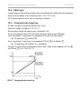
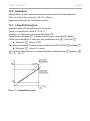
Combined mode (optional – with expansion board)
In combined mode, the evaporator operates along with the heater. The temper-
ature in the sauna cabin is lower (around 40 to 65 °C) than in sauna mode, but
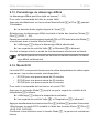
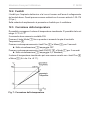
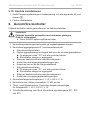
the relative humidity is much higher, ranging from 35% to 70%. The maximum
humidity that can be set depends on the temperature of the sauna. The higher
the sauna temperature, the lower the maximum humidity level that can be set
(see Fig. 1).
3.6. Sensor operating modes
The wave.com4 11 kW sauna controller can be operated with one, two or three
sensors.
Single sensor mode (F1)
Single sensor mode is the factory setting.
In single sensor mode, the sauna controller is operated with the heater sensor
with overheat cut-out only.
The sauna controller displays the actual temperature by default. The target
temperature is displayed while the setting is entered.
In single sensor mode, the maximum humidity that can be set (optional – with
expansion board) is based on the temperature above the heater and the humidity
is timed. Only the setpoint for the humidity (in % relative humidity) is shown on
the sauna controller display. The actual humidity in the sauna cabin when the
humidity is timed depends on the size of the cabin and the evaporator output,
andmaydierfromthesetpoint.
0
10
20
30
40
50
60
70
80
90
100
010 20 30 40 50 60 70 80 90 100 110
Temp
Feuchte
Fig. 1: Characteristic curve showing humidity relative to temperature
Humidity [%]
Temperature [°C]

Instructions for installation and use p. 12/38
Two-sensor mode with humidity/temperature sensor (FTS2)
(optional – with expansion board)
In two-sensor mode with humidity/temperature sensor, the sauna controller
displays the temperature measured by the humidity/temperature sensor as the
actual temperature.
In two-sensor mode with humidity/temperature sensor, the evaporator is regulat-
ed according to the humidity level measured in the cabin. The sauna controller
displays the actual humidity (in % relative humidity) in the sauna cabin.
Two-sensor mode with bench sensor (F2)
(optional – with expansion board)
In two-sensor mode with bench sensor, a second temperature sensor (bench
sensor) is installed above the rear sauna bench. The sauna controller displays
the temperature measured by the bench sensor as the actual temperature.
In two-sensor mode with bench sensor, the humidity is timed. Only the setpoint
for the humidity (in % relative humidity) is shown on the sauna controller display.
The actual humidity in the sauna cabin when the humidity is timed depends on
thesizeofthecabinandtheevaporatoroutput,andmaydierfromthesetpoint.
Two-sensor mode with humidity sensor (WC4-H-H)
(optional – with expansion board)
In two-sensor mode with humidity sensor, the sauna controller displays the tem-
perature measured by the heater sensor as the actual temperature. The evap-
orator is regulated according to the humidity measured in the cabin. The sauna
controller displays the actual humidity (in % relative humidity) in the sauna cabin.
Three-sensor mode with bench sensor (F2) and humidity sensor (WC4-H-Hx)
(optional – with expansion board)
In three-sensor mode with bench sensor and humidity sensor, the sauna controller
displays the temperature measured by the bench sensor as the actual temperature.
In three-sensor mode, the evaporator is regulated according to the humidity
measured in the cabin. The sauna controller displays the actual humidity (in %
relative humidity) in the sauna cabin.

EN
Instructions for installation and use p. 13/38
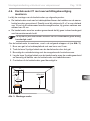
4. Installation
During installation observe the technical data; see Page 37:
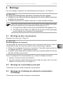
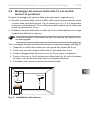
4.1. Installing the power unit
See Fig. 2 on Page 14.
ATTENTION!
Damage to the unit
The sauna controller is resistant to splashing water, but direct contact with water
could still damage it.
●Install the sauna controller in a dry place where the maximum humidity will
not exceed 95%.
●When installed in the sauna cabin, the cable bushings must not point upwards!
●The sensors may only be connected using the sensor cables supplied
with the unit, which are heat-resistant up to 150 °C.
●The heater sensor cables may NOT be longer than 10 m.
●Outside the cabin, the sensor cables can be extended using cables
that are not temperature-resistant.
ATTENTION!
Interference can impair signal transmission
●Route all sensor cables separately from other mains cables and control cables.
●Protect cables with only one layer of insulation by using a conduit (double
insulation).
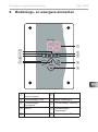
To install the power unit 1, carry out the following steps:
1. Takeothecoverofthepowerunit.
2. You can fasten the power unit to the supporting surface at the 4 corners of
the chassis (see arrows Fig. 4 on page 17)
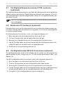
4.2. Installing the main switch
Follow the operating instructions for the switch.
4.3. Installing the cabin light and the light switch
Follow the operating instructions for the switch.

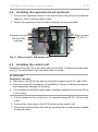
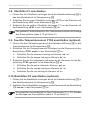
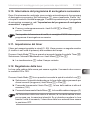
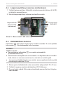
Installation instructions, only for experts p. 14/38
Fig. 2: Wave.com4 11 kW power unit
Basic module
WC4-B-11
Expansion board
WC4-H-PCB
(optional)
4.4. Installing the expansion board (optional)
1. Connecttheexpansionboardtothebaseboardusingthepre-congured
cables (L-N-PE) and the ribbon cable.
2. Fasten the expansion board in place using the screws provided.
4.5. Installing the control unit
Install the control unit 2 on the cabin wall no more than 10 metres from the power
unit 1. Pay attention to how the data cable is routed.
ATTENTION!
Damage to the unit
●The control unit 2 for the sauna controller is splash-proof (IP code IPX4).
●Only use a manual screwdriver for installation. Using a cordless screwdriver
may irreparably damage the housing.
●For installation inside the sauna cabin, maintain a distance of at least 30 cm
to the ceiling.
1. Cut the recess for the control unit, for example using a Ø 70 × 35 mm hole
cutter.
2. Connect the 4-pin plug to the RJ10 socket on the control unit.
3. Screw the housing to the cabin wall by screwing the 4 wood screws supplied
through the hole.

EN
Installation instructions, only for experts p. 15/38
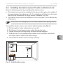
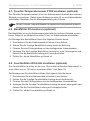
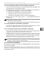
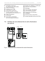
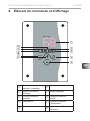
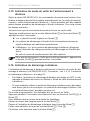
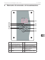
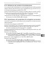
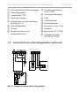
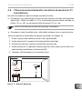
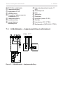
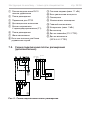
4.6. Installing the heater sensor F1 with overheat cut-out
Note the following points when installing the heater sensor:
●The heater sensor must be installed in the sauna cabin above the middle of
the sauna heater. For cabins up to 2 × 2 m a distance of 19 cm from the cabin
wall must be maintained, for larger cabins a distance of 35 cm.
●Theheatersensormustbeinstalledinsuchawaythatitisnotaectedby
inowingair.
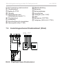
Fig. 3: Installing the sensor
To install the heater sensor, carry out the following steps (see Fig. 3):
1. Drill through the cabin ceiling with an 8 mm bit.
2. Pull the two 2-core heater sensor cable through the hole.
3. Fasten the sensor housing using the wood screws supplied.
4. Guidethetwo2-coreheatersensorcablesuptothepowerunitandx
the heater sensor cables with cable clamps.
5. Checkthattheheatersensorisrmlyfastened.
Take care not to damage any of the sensor cables when pulling them in.
19 cm
35 cm
> 2 × 2 m
< 2 × 2 m
150 cm
F1
WC4-H-H

Installation instructions, only for experts p. 16/38
4.8. Installing the bench sensor F2 (optional)
The bench sensor must be installed on the wall of the cabin above the rear bench
seat. A distance of about 15 cm from the ceiling of the cabin must be maintained.
To install the bench sensor, carry out the following steps:
1. Drill through the cabin wall with an 8 mm drill bit.
2. Pull the 2-core bench sensor cable through the hole.
3. Fasten the sensor housing using the wood screws supplied.
4. Guide the 2-core bench sensor cable up to the power unit and fasten it with
cable clips.
5. Checkthatthebenchsensorisrmlyfastened.
4.7. Installing the humidity/temperature sensor FTS2
(optional)
The humidity/temperature sensor must be installed on the wall of the cabin above
the rear bench seat. A distance of about 15 cm from the ceiling of the cabin must
be maintained. Follow the installation instructions for the sensor.
A wooden housing is optionally available for the humidity/temperature
sensor.
4.9. Installing the humidity sensor WC4-H-H (optional)
The humidity sensor must be installed in the middle of the side wall furthest from
the heater at a height of around 150 cm (Fig. 3 on page 15).
To install the humidity sensor, carry out the following steps:
1. Drill through the cabin wall with an 8 mm drill bit.
2. Pull the 3-core humidity sensor cable through the hole.
3. Fasten the sensor housing using the wood screws supplied.
4. Guide the 3-core humidity sensor cable up to the power unit and fasten it
with cable clips.
5. Checkthatthehumiditysensorisrmlyfastened.

EN
Installation instructions, only for experts p. 17/38
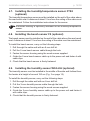
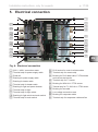
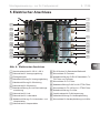
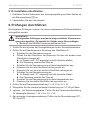
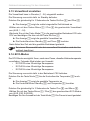
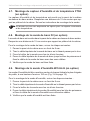
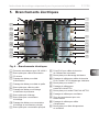
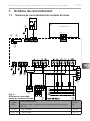
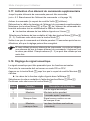
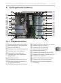
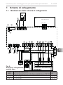
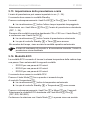
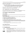
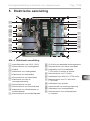
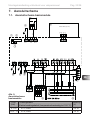
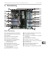
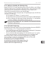
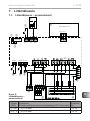
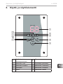
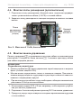
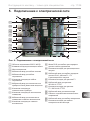
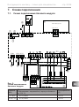
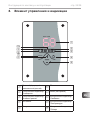
5. Electrical connection
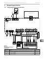
4
k
i5
7
a
c RJ10 socket for control unit data cable
d Terminal strip for remote strip
e Bushing for RJ10 data cable, F1/F2 sensors
and remote start device
f Terminal strip for F1 sensor
g Bushing for WC4-H-H / FTS2 sensor
h
Terminal strip for F2 / WC4-H-H / FTS2 sensor
i Bushing for fan cable
j Low voltage connection area
k Bushing for evaporator cable
l Terminal strip for evaporator cable and fan
1 230 V / 400 V connection areas
2 Terminal strip for power supply cable
3 Earth rail
4 Bushing for power supply cable
5 Bushing for heater cable
6 Terminal strip for heater cable
7 Bushing for light and power booster
8 Terminal strip for light
9 Terminal strip for light switch
a Bushing for light switch and main switch
b Terminal strip for main switch
1
2
3
6
8
9
b
c
d
e
f
g
h
l
j
Fig. 4: Electrical connection

Installation instructions, only for experts p. 18/38
5.1. Connecting the power supply cable and heater
1. Guide the power supply and heater cable through the bushings 4 and 5
into the 230 V/400 V connection area 1.
2. Connect the cables to the corresponding terminal strips 2 and 6.
Follow the operating instructions for each device.
5.2. Connecting the evaporator (optional)
1. Guide the evaporator cable (optional with expansion board) through
the bushing k into the 230 V/400 V connection area 1.
2. Connect the cables to the corresponding terminal strips l.
Follow the operating instructions for the evaporator.
If the evaporator does not have an automatic low-water indicator, use
a jumper to connect terminal “U1” to terminal “WM” or change the setting
of the acoustic signal (see Page 32).
5.3. Connecting the control unit
1. Guide the control unit connection cable through the bushing e into the
low-voltage connection area j.
2. Connect the plug of the RJ-10 cable to the connection socket c.
The wave.com4 11 kW sauna controllers allow up to 4 control units to
be operated on one power unit. Use the Y-adapter (see “3.3. Optional
accessories” on page 9) to connect the optional control units.
Note “5. Electrical connection” on page 17 and “7.1. Connec-
tion diagram of basic module” on page 23 and “7.2. Connection
diagram for the expansion board (optional)” on page 24.

EN
Installation instructions, only for experts p. 19/38
5.4. Connecting an external main switch
The main switch is not included on delivery.
1. Guide the main switch connection cable through the bushing a into
the 230 V/400 V connection area 1.
2. Connect the cable to terminal strip b. Follow the operating instructions
for the switch.
5.5. Connecting the light
1. Guide the light cable through the bushing 7 into the 230 V/400 V connec-
tion area 1.
2. Connect the light cable to terminal strip 8. Follow the operating instructions
for the switch.
5.6. Connecting an external light switch
The light switch is not included on delivery.
3. Guide the light switch connection cable through the bushing a into
the 230 V/400 V connection area 1.
4. Connect the cable to terminal strip 9. Follow the operating instructions
for the switch.
5.7. Connecting a fan (optional)
1. Guide the fan cable through the bushing i into the 230 V/400 V connec-
tion area 1.
2. Connect the fan cable to terminal strip l. Follow the operating instructions
for the fan.
The contacts are bridged on delivery. Remove the wire jumper for in-
stallation

Installation instructions, only for experts p. 20/38
5.8. Connecting the heater sensor F1
1. Guide the heater sensor cables through the bushing e into the low-voltage
connection area j.
2. Connect the red heater sensor wires (STB) to the terminals labelled “R-R”
in terminal strip f.
3. Connect the white heater sensor wires (F1) to the terminals labelled “W-W”
in terminal strip f.
5.9. Connecting the humidity/temperature sensor FTS2
(optional)
1. Guide the sensor cables through the bushing g into the low-voltage con-
nection area j.
2. Connect the temperature sensor wires to the terminals labelled “FTS2: sw-br”
in terminal strip h.
a. Connect the black wire to the terminal labelled “sw”.
b. Connect the brown wire to the terminal labelled “br”.
3. Connect the humidity sensor wires to the terminals labelled “FTS2: gn-or-rt”
in terminal strip h.
c. Connect the green wire to the terminal labelled “gn”.
d. Connect the orange wire to the terminal labelled “or”.
e. Connect the red wire to the terminal labelled “rt”.
5.10. Connecting the bench sensor F2 (optional)
1. Guide the bench sensor cables through the bushing e into the low-voltage
connection area j.
2. Connect the bench sensor wires to the terminals labelled “F2: ws-ws” in
terminal strip h.
For timed humidity in single-sensor mode, the dummy sensor must be
installed (see 5.12 on page 21).
For timed humidity in two-sensor mode (F1 and F2), the dummy sensor
must be installed (see 5.12 on page 21)
La page est en cours de chargement...
La page est en cours de chargement...
La page est en cours de chargement...
La page est en cours de chargement...
La page est en cours de chargement...
La page est en cours de chargement...
La page est en cours de chargement...
La page est en cours de chargement...
La page est en cours de chargement...
La page est en cours de chargement...
La page est en cours de chargement...
La page est en cours de chargement...
La page est en cours de chargement...
La page est en cours de chargement...
La page est en cours de chargement...
La page est en cours de chargement...
La page est en cours de chargement...
La page est en cours de chargement...
La page est en cours de chargement...
La page est en cours de chargement...
La page est en cours de chargement...
La page est en cours de chargement...
La page est en cours de chargement...
La page est en cours de chargement...
La page est en cours de chargement...
La page est en cours de chargement...
La page est en cours de chargement...
La page est en cours de chargement...
La page est en cours de chargement...
La page est en cours de chargement...
La page est en cours de chargement...
La page est en cours de chargement...
La page est en cours de chargement...
La page est en cours de chargement...
La page est en cours de chargement...
La page est en cours de chargement...
La page est en cours de chargement...
La page est en cours de chargement...
La page est en cours de chargement...
La page est en cours de chargement...
La page est en cours de chargement...
La page est en cours de chargement...
La page est en cours de chargement...
La page est en cours de chargement...
La page est en cours de chargement...
La page est en cours de chargement...
La page est en cours de chargement...
La page est en cours de chargement...
La page est en cours de chargement...
La page est en cours de chargement...
La page est en cours de chargement...
La page est en cours de chargement...
La page est en cours de chargement...
La page est en cours de chargement...
La page est en cours de chargement...
La page est en cours de chargement...
La page est en cours de chargement...
La page est en cours de chargement...
La page est en cours de chargement...
La page est en cours de chargement...
La page est en cours de chargement...
La page est en cours de chargement...
La page est en cours de chargement...
La page est en cours de chargement...
La page est en cours de chargement...
La page est en cours de chargement...
La page est en cours de chargement...
La page est en cours de chargement...
La page est en cours de chargement...
La page est en cours de chargement...
La page est en cours de chargement...
La page est en cours de chargement...
La page est en cours de chargement...
La page est en cours de chargement...
La page est en cours de chargement...
La page est en cours de chargement...
La page est en cours de chargement...
La page est en cours de chargement...
La page est en cours de chargement...
La page est en cours de chargement...
La page est en cours de chargement...
La page est en cours de chargement...
La page est en cours de chargement...
La page est en cours de chargement...
La page est en cours de chargement...
La page est en cours de chargement...
La page est en cours de chargement...
La page est en cours de chargement...
La page est en cours de chargement...
La page est en cours de chargement...
La page est en cours de chargement...
La page est en cours de chargement...
La page est en cours de chargement...
La page est en cours de chargement...
La page est en cours de chargement...
La page est en cours de chargement...
La page est en cours de chargement...
La page est en cours de chargement...
La page est en cours de chargement...
La page est en cours de chargement...
La page est en cours de chargement...
La page est en cours de chargement...
La page est en cours de chargement...
La page est en cours de chargement...
La page est en cours de chargement...
La page est en cours de chargement...
La page est en cours de chargement...
La page est en cours de chargement...
La page est en cours de chargement...
La page est en cours de chargement...
La page est en cours de chargement...
La page est en cours de chargement...
La page est en cours de chargement...
La page est en cours de chargement...
La page est en cours de chargement...
La page est en cours de chargement...
La page est en cours de chargement...
La page est en cours de chargement...
La page est en cours de chargement...
La page est en cours de chargement...
La page est en cours de chargement...
La page est en cours de chargement...
La page est en cours de chargement...
La page est en cours de chargement...
La page est en cours de chargement...
La page est en cours de chargement...
La page est en cours de chargement...
La page est en cours de chargement...
La page est en cours de chargement...
La page est en cours de chargement...
La page est en cours de chargement...
La page est en cours de chargement...
La page est en cours de chargement...
La page est en cours de chargement...
La page est en cours de chargement...
La page est en cours de chargement...
La page est en cours de chargement...
La page est en cours de chargement...
La page est en cours de chargement...
La page est en cours de chargement...
La page est en cours de chargement...
La page est en cours de chargement...
La page est en cours de chargement...
La page est en cours de chargement...
La page est en cours de chargement...
La page est en cours de chargement...
La page est en cours de chargement...
La page est en cours de chargement...
La page est en cours de chargement...
La page est en cours de chargement...
La page est en cours de chargement...
La page est en cours de chargement...
La page est en cours de chargement...
La page est en cours de chargement...
La page est en cours de chargement...
La page est en cours de chargement...
La page est en cours de chargement...
La page est en cours de chargement...
La page est en cours de chargement...
La page est en cours de chargement...
La page est en cours de chargement...
La page est en cours de chargement...
La page est en cours de chargement...
La page est en cours de chargement...
La page est en cours de chargement...
La page est en cours de chargement...
La page est en cours de chargement...
La page est en cours de chargement...
La page est en cours de chargement...
La page est en cours de chargement...
La page est en cours de chargement...
La page est en cours de chargement...
La page est en cours de chargement...
La page est en cours de chargement...
La page est en cours de chargement...
La page est en cours de chargement...
La page est en cours de chargement...
La page est en cours de chargement...
La page est en cours de chargement...
La page est en cours de chargement...
La page est en cours de chargement...
La page est en cours de chargement...
La page est en cours de chargement...
La page est en cours de chargement...
La page est en cours de chargement...
La page est en cours de chargement...
La page est en cours de chargement...
La page est en cours de chargement...
La page est en cours de chargement...
La page est en cours de chargement...
La page est en cours de chargement...
La page est en cours de chargement...
La page est en cours de chargement...
La page est en cours de chargement...
La page est en cours de chargement...
La page est en cours de chargement...
La page est en cours de chargement...
La page est en cours de chargement...
La page est en cours de chargement...
La page est en cours de chargement...
La page est en cours de chargement...
La page est en cours de chargement...
La page est en cours de chargement...
La page est en cours de chargement...
La page est en cours de chargement...
La page est en cours de chargement...
La page est en cours de chargement...
La page est en cours de chargement...
La page est en cours de chargement...
La page est en cours de chargement...
La page est en cours de chargement...
La page est en cours de chargement...
La page est en cours de chargement...
La page est en cours de chargement...
La page est en cours de chargement...
La page est en cours de chargement...
La page est en cours de chargement...
La page est en cours de chargement...
La page est en cours de chargement...
La page est en cours de chargement...
La page est en cours de chargement...
La page est en cours de chargement...
La page est en cours de chargement...
La page est en cours de chargement...
La page est en cours de chargement...
La page est en cours de chargement...
La page est en cours de chargement...
La page est en cours de chargement...
La page est en cours de chargement...
La page est en cours de chargement...
La page est en cours de chargement...
La page est en cours de chargement...
La page est en cours de chargement...
La page est en cours de chargement...
La page est en cours de chargement...
La page est en cours de chargement...
La page est en cours de chargement...
La page est en cours de chargement...
La page est en cours de chargement...
La page est en cours de chargement...
La page est en cours de chargement...
La page est en cours de chargement...
La page est en cours de chargement...
La page est en cours de chargement...
La page est en cours de chargement...
La page est en cours de chargement...
La page est en cours de chargement...
La page est en cours de chargement...
La page est en cours de chargement...
La page est en cours de chargement...
La page est en cours de chargement...
La page est en cours de chargement...
La page est en cours de chargement...
La page est en cours de chargement...
La page est en cours de chargement...
La page est en cours de chargement...
La page est en cours de chargement...
La page est en cours de chargement...
La page est en cours de chargement...
La page est en cours de chargement...
La page est en cours de chargement...
La page est en cours de chargement...
La page est en cours de chargement...
La page est en cours de chargement...
La page est en cours de chargement...
La page est en cours de chargement...
La page est en cours de chargement...
La page est en cours de chargement...
La page est en cours de chargement...
La page est en cours de chargement...
La page est en cours de chargement...
La page est en cours de chargement...
La page est en cours de chargement...
La page est en cours de chargement...
La page est en cours de chargement...
La page est en cours de chargement...
La page est en cours de chargement...
La page est en cours de chargement...
La page est en cours de chargement...
La page est en cours de chargement...
La page est en cours de chargement...
La page est en cours de chargement...
La page est en cours de chargement...
La page est en cours de chargement...
La page est en cours de chargement...
La page est en cours de chargement...
La page est en cours de chargement...
La page est en cours de chargement...
-
 1
1
-
 2
2
-
 3
3
-
 4
4
-
 5
5
-
 6
6
-
 7
7
-
 8
8
-
 9
9
-
 10
10
-
 11
11
-
 12
12
-
 13
13
-
 14
14
-
 15
15
-
 16
16
-
 17
17
-
 18
18
-
 19
19
-
 20
20
-
 21
21
-
 22
22
-
 23
23
-
 24
24
-
 25
25
-
 26
26
-
 27
27
-
 28
28
-
 29
29
-
 30
30
-
 31
31
-
 32
32
-
 33
33
-
 34
34
-
 35
35
-
 36
36
-
 37
37
-
 38
38
-
 39
39
-
 40
40
-
 41
41
-
 42
42
-
 43
43
-
 44
44
-
 45
45
-
 46
46
-
 47
47
-
 48
48
-
 49
49
-
 50
50
-
 51
51
-
 52
52
-
 53
53
-
 54
54
-
 55
55
-
 56
56
-
 57
57
-
 58
58
-
 59
59
-
 60
60
-
 61
61
-
 62
62
-
 63
63
-
 64
64
-
 65
65
-
 66
66
-
 67
67
-
 68
68
-
 69
69
-
 70
70
-
 71
71
-
 72
72
-
 73
73
-
 74
74
-
 75
75
-
 76
76
-
 77
77
-
 78
78
-
 79
79
-
 80
80
-
 81
81
-
 82
82
-
 83
83
-
 84
84
-
 85
85
-
 86
86
-
 87
87
-
 88
88
-
 89
89
-
 90
90
-
 91
91
-
 92
92
-
 93
93
-
 94
94
-
 95
95
-
 96
96
-
 97
97
-
 98
98
-
 99
99
-
 100
100
-
 101
101
-
 102
102
-
 103
103
-
 104
104
-
 105
105
-
 106
106
-
 107
107
-
 108
108
-
 109
109
-
 110
110
-
 111
111
-
 112
112
-
 113
113
-
 114
114
-
 115
115
-
 116
116
-
 117
117
-
 118
118
-
 119
119
-
 120
120
-
 121
121
-
 122
122
-
 123
123
-
 124
124
-
 125
125
-
 126
126
-
 127
127
-
 128
128
-
 129
129
-
 130
130
-
 131
131
-
 132
132
-
 133
133
-
 134
134
-
 135
135
-
 136
136
-
 137
137
-
 138
138
-
 139
139
-
 140
140
-
 141
141
-
 142
142
-
 143
143
-
 144
144
-
 145
145
-
 146
146
-
 147
147
-
 148
148
-
 149
149
-
 150
150
-
 151
151
-
 152
152
-
 153
153
-
 154
154
-
 155
155
-
 156
156
-
 157
157
-
 158
158
-
 159
159
-
 160
160
-
 161
161
-
 162
162
-
 163
163
-
 164
164
-
 165
165
-
 166
166
-
 167
167
-
 168
168
-
 169
169
-
 170
170
-
 171
171
-
 172
172
-
 173
173
-
 174
174
-
 175
175
-
 176
176
-
 177
177
-
 178
178
-
 179
179
-
 180
180
-
 181
181
-
 182
182
-
 183
183
-
 184
184
-
 185
185
-
 186
186
-
 187
187
-
 188
188
-
 189
189
-
 190
190
-
 191
191
-
 192
192
-
 193
193
-
 194
194
-
 195
195
-
 196
196
-
 197
197
-
 198
198
-
 199
199
-
 200
200
-
 201
201
-
 202
202
-
 203
203
-
 204
204
-
 205
205
-
 206
206
-
 207
207
-
 208
208
-
 209
209
-
 210
210
-
 211
211
-
 212
212
-
 213
213
-
 214
214
-
 215
215
-
 216
216
-
 217
217
-
 218
218
-
 219
219
-
 220
220
-
 221
221
-
 222
222
-
 223
223
-
 224
224
-
 225
225
-
 226
226
-
 227
227
-
 228
228
-
 229
229
-
 230
230
-
 231
231
-
 232
232
-
 233
233
-
 234
234
-
 235
235
-
 236
236
-
 237
237
-
 238
238
-
 239
239
-
 240
240
-
 241
241
-
 242
242
-
 243
243
-
 244
244
-
 245
245
-
 246
246
-
 247
247
-
 248
248
-
 249
249
-
 250
250
-
 251
251
-
 252
252
-
 253
253
-
 254
254
-
 255
255
-
 256
256
-
 257
257
-
 258
258
-
 259
259
-
 260
260
-
 261
261
-
 262
262
-
 263
263
-
 264
264
-
 265
265
-
 266
266
-
 267
267
-
 268
268
-
 269
269
-
 270
270
-
 271
271
-
 272
272
-
 273
273
-
 274
274
-
 275
275
-
 276
276
-
 277
277
-
 278
278
-
 279
279
-
 280
280
-
 281
281
-
 282
282
-
 283
283
-
 284
284
-
 285
285
-
 286
286
-
 287
287
-
 288
288
-
 289
289
-
 290
290
-
 291
291
-
 292
292
-
 293
293
-
 294
294
-
 295
295
-
 296
296
-
 297
297
-
 298
298
-
 299
299
-
 300
300
-
 301
301
-
 302
302
-
 303
303
-
 304
304
-
 305
305
-
 306
306
-
 307
307
-
 308
308


Sentiotec wave.com4 11kW Manuel utilisateur
- Taper
- Manuel utilisateur
dans d''autres langues
- italiano: Sentiotec wave.com4 11kW Manuale utente
- Nederlands: Sentiotec wave.com4 11kW Handleiding
Documents connexes
-
Sentiotec K1-next Manuel utilisateur
-
-
-
-
-
-
-
-
-